Abstract
MEMS micro-resonators often operate in a multi-physics coupling environment involving electrostatic fields, molecular force fields, and structural force fields, exhibiting significant nonlinear natural frequency perturbation and frequency drift, which leads to large fluctuations in output frequency. Existing methods struggle to simultaneously characterize the nonlinear coupling effects of Casimir force and electrostatic force, and lack adaptive compensation capability for time-varying disturbances. To overcome this bottleneck, this paper proposes a frequency stabilization control method based on nonlinear coupled dynamics and adaptive compensation using a fuzzy emotional neural network. The main contributions are as follows: a distributed-parameter nonlinear vibration model incorporating dynamic electrostatic force and Casimir force is established, revealing the intrinsic competitive mechanism through which initial gap and beam length affect frequency drift; a fuzzy emotional neural network with dynamic displacement, dynamic electrostatic force, and dynamic Casimir force as multi-field fusion inputs is designed to achieve high-precision real-time estimation of the system's unmodeled dynamics; an error-constrained barrier Lyapunov function is constructed and combined with backstepping control to realize adaptive feedforward-feedback composite compensation of the excitation voltage between the plates. Experimental results show that the proposed method achieves high-precision frequency stabilization control under different micro-resonator lengths (500 μm, 1000 μm, and 1500 μm), with the root mean square error of frequency tracking as low as 0.46×10⁴ Hz, which is reduced by approximately one order of magnitude compared with the PID method. The maximum Allan variance is only 4.5×10⁻¹⁰, reduced by approximately two orders of magnitude compared with the open-loop state, meeting the accuracy requirements of industrial-grade frequency sources such as 5G base station local oscillators and inertial navigation system clocks. The proposed method does not rely on modifying the device geometry and is insensitive to changes in structural dimensions, providing a feasible and robust intelligent control solution for the engineering application of high-precision MEMS resonators.
Highlights
- Establishment of a distributed-parameter nonlinear vibration model incorporating dynamic electrostatic force and Casimir force, revealing the intrinsic competitive mechanism of frequency drift.
- Design of a fuzzy emotional neural network with multi-field fusion inputs to achieve high-precision real-time estimation of unmodeled dynamics.
- Construction of an error-constrained barrier Lyapunov function combined with backstepping control to realize adaptive feedforward-feedback composite compensation.
1. Introduction
Micro-electro-mechanical systems (MEMS) micro-resonators serve as the core physical carriers in micro-nano sensing and frequency control fields [1]. As a class of micro-nano devices that convert mechanical motion into electrical signals and vice versa, their operating principle leverages the periodic vibration of mechanical structures [2] to transform changes in physical quantities – such as mass, force, acceleration, or pressure – into precisely measurable shifts in resonant frequency. The self-excited oscillation circuit enables MEMS resonators to serve as frequency sources, generating stable timing signals and widely used in various fields [3]. However, MEMS microresonators operate in a multi physics coupled environment [4], and their dynamic behavior is affected by nonlinear stiffness disturbances leading to frequency drift, which limits their high-precision application performance and reliability [5].
Currently, numerous studies have been dedicated to improving the frequency stability of resonators and similar systems. These methods can be broadly categorized into three types: structural optimization design, physical effect-based active compensation, and feedback control strategies.
In terms of structural optimization design, Zhou et al. [6] effectively mitigated the nonlinear stiffness of clamped-clamped beam resonators under large deformation caused by axial forces by designing H-shaped structural beams. They systematically analyzed the effects of different beam lengths and thicknesses on nonlinear stiffness and derived an analytical expression for nonlinear stiffness using the Rayleigh-Ritz energy method. Furthermore, a virtually coupled resonator design paradigm has been proposed, which achieves energy localization through frequency offset. This paradigm achieves an amplitude ratio sensitivity of 24.4 (N/m)-1 in open-loop mode and 33.0 (N/m)-1 in closed-loop mode [7]. These approaches suppress nonlinearity at its source, but are essentially open-loop in nature and struggle to adapt to real-time varying disturbance environments.
Regarding physical effect-based active compensation, Suliga, K. et al. [8] compensated for phase drift by electro-optic effect, neglecting nonlinear stiffness effect, the applicability is poor; Alanazi et al. used iterative learning algorithms, but lacked multi field coupled dynamic models, resulting in insufficient suppression accuracy [9]; Raju et al. used the moth flame optimization algorithm to optimize the PID controller, relying on linear feedback to solve nonlinear problems with limitations [10]; Kuliski et al. are based on the Hamiltonian principle and use open-loop optimization, which makes it difficult to ensure long-term frequency stability [11].
In terms of feedback control strategies, research in recent years has shown a clear trend toward data-driven and intelligent approaches. Huan et al. [12] proposed an adaptive frequency stabilization system based on mode coupling, which regulates the oscillation frequency of a linear high-frequency resonator through a nonlinear low-frequency resonator, improving frequency stability by nearly 700 times over a time scale of 1000 seconds. Xiao et al. [13] demonstrated a temperature-controlled piezoelectric MEMS dual-resonator platform that achieves closed-loop temperature compensation through an on-chip micro-oven, attaining frequency stability of ±100 ppb over the industrial temperature range of –40 to 85 °C. Xu et al. [14] further developed a multifunctional MEMS resonator suitable for the blue-sideband excitation scheme, providing a stable reference using dual-mode sum frequency, and achieved a long-term stability of 1.5 ppb at 1000 seconds. These advances indicate that combining adaptive mechanisms with multi-physics compensation represents an effective pathway to enhance the frequency stabilization performance of MEMS resonators.
Nevertheless, existing studies still suffer from the following critical limitations. First, most methods adopt overly simplified descriptions of multi-field coupling and fail to establish a nonlinear dynamic model that simultaneously characterizes the combined effects of electrostatic forces and Casimir forces. Second, although a few studies have employed neural networks for nonlinear estimation, the network structures are not tightly integrated with the physical coupling mechanisms of MEMS systems, lacking systematic designs for multi-source physical field information fusion. Third, existing adaptive control strategies mostly focus on compensating for single disturbance sources, offering limited capability for comprehensive compensation of equivalent nonlinear stiffness perturbations induced by multi-field coupling. These limitations result in significant fluctuations in the output frequency of MEMS micro-resonators when dealing with time-varying disturbances in complex engineering environments.
To address these challenges, this paper proposes a frequency stabilization control method based on nonlinear coupled dynamics and adaptive compensation using a fuzzy emotional neural network. The core contributions are as follows: (1) A distributed-parameter nonlinear vibration model incorporating dynamic electrostatic forces and Casimir forces is established and analytically solved using the Lindstedt-Poincaré perturbation method, precisely quantifying the stiffness softening/hardening effects caused by the coupling of electric fields and molecular forces, thereby providing an accurate theoretical benchmark and target trajectory for frequency stabilization control. (2) A fuzzy emotional neural network with dynamic displacement, dynamic electrostatic force, and dynamic Casimir force as core inputs is designed to achieve high-dimensional fusion of multi-physics information and high-precision real-time estimation of nonlinear dynamic functions, offering stronger interpretability and estimation stability compared to existing black-box neural network methods. (3) An error-constrained barrier Lyapunov function is constructed and combined with a backstepping control framework to generate online control laws for the excitation voltage between electrodes, realizing adaptive feedforward-feedback composite compensation for multi-field coupled nonlinear stiffness perturbations via electric field forces. Under different micro-resonator lengths, the proposed method achieves a maximum Allan variance of only 4.5×10⁻¹⁰, is insensitive to changes in structural dimensions, and exhibits excellent engineering robustness and practical application potential.
2. Frequency stabilization control methods for MEMS micro-resonators
2.1. Calculation of nonlinear natural frequency of MEMS micro-resonators under multi-physics coupling
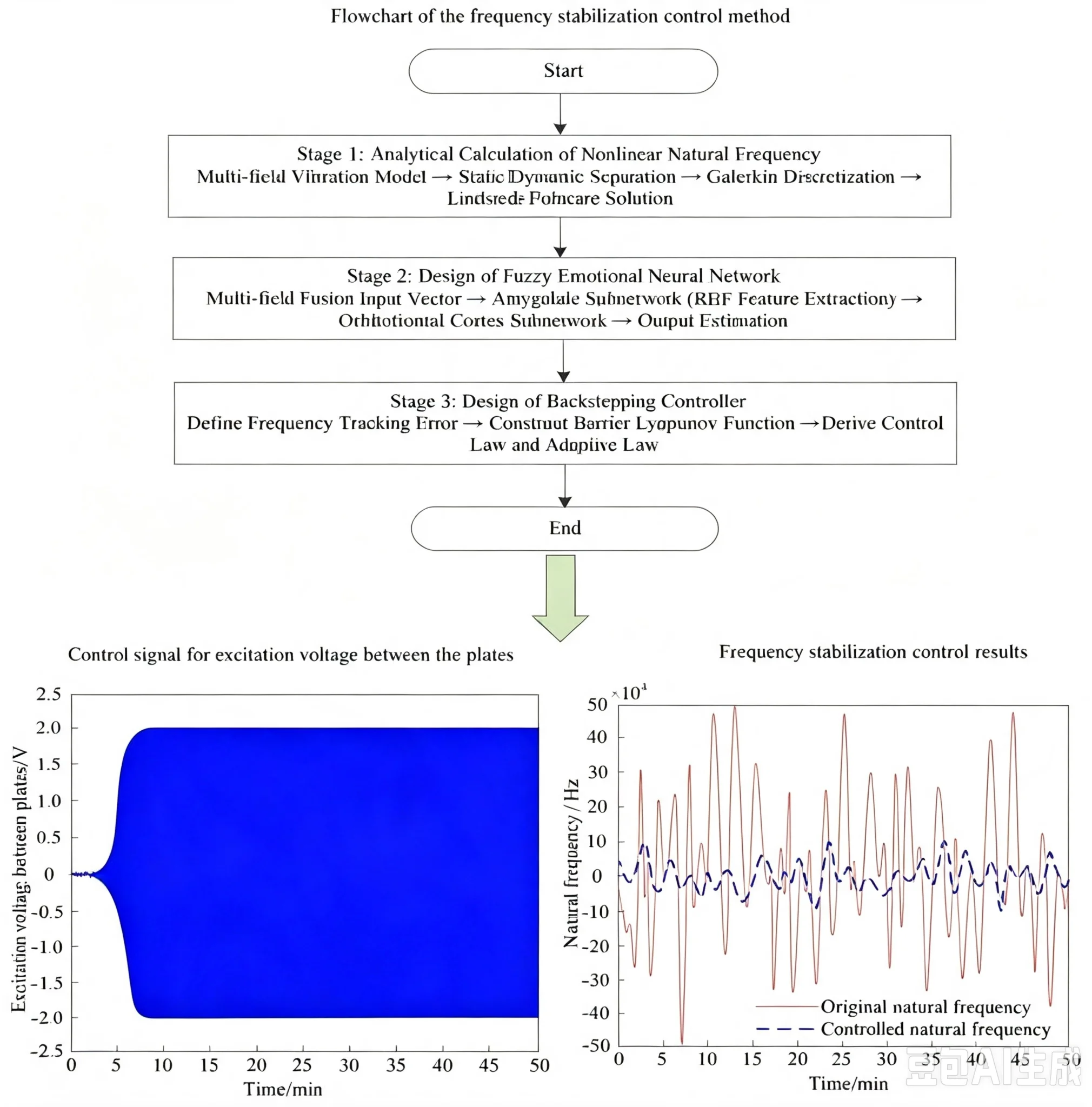
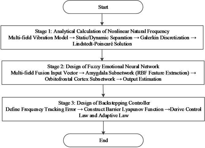
Due to the coupling effect of multiple physical fields, the dynamic behavior of MEMS microresonators exhibits strong nonlinearity and parameter sensitivity, and their natural frequencies are not constant but dynamically vary with the strength of the coupling field. Therefore, by establishing a multi-field coupled nonlinear vibration model and calculating its expected nonlinear natural frequency, this study reveals at the mechanism level how interactions between electric fields, molecular force fields, and structural fields influence the system's equivalent stiffness, thereby quantitatively characterizing the root cause of frequency drift. Building upon the structural force field, this study incorporates the molecular force field (dynamic Casimir force) and the electric force field (dynamic electrostatic force) to establish a nonlinear vibration model for MEMS micro-resonators under multi-field coupling. This approach reveals the multi-physics interaction mechanism governing MEMS micro-resonators and determines their expected nonlinear natural frequency. To facilitate understanding of the overall research flow of the proposed method in this chapter, Fig. 1 presents the complete roadmap from model establishment, perturbation solution, neural network design, to backstepping controller design.
The MEMS micro-resonator consists of a micro-resonant beam and a lower electrode plate, both fabricated from single-crystal silicon. The micro-resonant beam has a length of and a width of . The material’s Young’s modulus is , and its density is . The material parameters used in this paper (elastic modulus of 169 GPa, density of 2330 kg/m3, and Poisson’s ratio of 0.28) are derived from the standard SOI-MEMS process data sheet and have been verified by sampling the same batch of wafers using a nanoindenter. The geometric parameters (micro-resonator lengths of 500, 1000, and 1500 μm, width of 20 μm, thickness of 10 μm, and initial gap of 0.45 to 0.55 μm) are determined based on measurements from a white light interferometer. The micro-resonator is a slender beam. Neglecting the effects of cross-sectional shear deformation and moment of inertia [15], it only undergoes displacement in the -direction. Based on vibration theory, the multi-field coupled vibration model for MEMS micro-resonators is:
where, is the elastic modulus of single-crystal silicon; is the moment of inertia of the micro-resonator cross-section about the central axis; is the material density of single-crystal silicon; is the cross-sectional area of the micro-resonator; is the axial force on the micro-resonator; is the total load per unit length on the micro-resonator; represents the position coordinate along the length of the micro-resonator; is the time variable.
To separate static and dynamic responses, the total displacement is decomposed into the sum of static and dynamic displacements:
where, represents the static displacement of the MEMS micro-resonator; denotes the dynamic displacement of the MEMS micro-resonator.
Fig. 1Flowchart of the frequency stabilization control method
The distributed load per unit length is composed of both electrostatic field forces and Casimir forces:
where, is the electrostatic force per unit length; is the Casimir force per unit length.
When the plate gap of the MEMS micro-resonator enters the submicron scale (initial gap 0.45-0.55 μm in the experiment), the Casimir force arising from quantum electrodynamic effects becomes a non-negligible surface force. The Casimir force per unit length is given by:
where, is the theoretical coefficient derived from integrating the Casimir force; 1.0546×10⁻³⁴ J⋅s is Planck’s constant; 2.9979×10⁸ m/s is the speed of light; is the width of the micro-resonator; is the initial gap between plates; is the total displacement of the micro-resonator. Under the parameters used in this paper ( 0.5 μm, 20 μm), the Casimir force per unit length is approximately 2.6×10⁻⁵ N/m. Although its magnitude is only about 0.04 % of the elastic restoring force, this force is inversely proportional to the fourth power of the gap distance, exhibiting extremely strong nonlinear characteristics. In applications requiring ultra-high frequency stability (this paper requires an Allan variance ≤ 4.5×10⁻¹⁰), the perturbation of the equivalent stiffness caused by the Casimir force is a non-negligible source of frequency drift.
Performing a Taylor expansion at the static displacement , yields the dynamic Casimir force:
where, , , and are the first, second, and third-order theoretical coefficients obtained from the Taylor expansion.
The electric force per unit length is:
where, 8.854×10⁻¹² F/m is the permittivity of free space; is the relative permittivity of the dielectric (in this paper, the environment is vacuum, ); is the excitation voltage between the plates.
Expanding Taylor at the static displacement , yields the dynamic electrostatic force:
Substituting Eq. (5) and (7) into Eq. (3) yields the dynamic load:
where, , and are the first-, second-, and third-order equivalent coefficients of multi-field coupling, respectively, reflecting the superimposed contributions of electrostatic force and Casimir force at each order.
Substituting the dynamic displacement and dynamic load into Eq. (1) yields the nonlinear dynamic model of the MEMS micro-resonator under multi-field coupling:
This model comprehensively describes the interaction mechanism of MEMS micro-resonators under the coupled fields of electric force, molecular force, and structural mechanics. Through the coefficients , , and directly quantifies the contribution weights of electric field forces and molecular forces at different orders, clearly distinguishing the sources of linear stiffness correction and nonlinear stiffness softening/hardening effects [16]. This enables precise identification of the core causes of frequency drift, providing a critical theoretical basis for frequency stabilization control of MEMS micro-resonators [17].
To separate the spatial and temporal variables, the Galerkin method is employed to decompose the dynamic displacement into the product of a modal function and a generalized coordinate as , where is the modal function satisfying the boundary conditions and is the generalized coordinate. For a clamped-clamped beam, the first-order modal function can be taken as . Substituting this decomposition into Eq. (9), multiplying both sides by and integrating over , the equation of motion for the generalized coordinate is obtained using modal orthogonality as follows:
where, is the modal function of the MEMS micro-resonator, describing the spatial distribution characteristics of vibration; is the generalized coordinate, describing the temporal evolution characteristics of vibration [18]; is the generalized acceleration; is the spatial average of the modal function .
Define the linear natural frequency of the MEMS micro-resonator as . Setting both sides of Eq. (10) equal to yields:
where, ; .
Rearranging yields the nonlinear dynamic model in generalized time coordinate:
Solve the nonlinear dynamical model in Eq. (12) using the Liouvin-Poincaré method, setting:
where, denotes the order of the power series expansion. The free frequency of the nonlinear dynamical model is also expanded as a power series in :
where, is the desired nonlinear natural frequency of the MEMS micro-resonator; is the frequency correction coefficient.
Substituting Eqs. (13) and (14) into Eq. (12) and equating the homogeneous coefficients of yields:
Whose zero-order solution is:
where: is the zero-order vibration amplitude; and are the zero-order generalized coordinates and zero-order generalized accelerations.
Substituting Eq. (16) into the first-order approximation equation , and setting the coefficient of to zero to eliminate the duration term (non-periodic term), yields the first-order frequency correction coefficient:
Similarly, the second-order frequency correction coefficient is obtained:
where, is the contribution coefficient of the square term in , reflecting the second-order cumulative effect of linear stiffness correction; is the contribution coefficient of the square term in , embodying the higher-order coupling effect of second-order nonlinearity [19]; is the contribution coefficient of the cross-term between and , reflecting the interaction between linear and second-order nonlinear effects [20].
Substituting Eqs. (17) and (18) into Eq. (14) yields the expected nonlinear natural frequency of the MEMS micro-resonator under multi-field coupling:
2.2. Frequency-dependent frequency control under nonlinear stiffness softening/hardening effects
In multi-physics coupling environments, while the calculation of nonlinear natural frequencies for MEMS micro-resonators theoretically reveals the mechanism of frequency drift and provides a desired frequency reference, actual systems experience time-varying disturbances, model uncertainties, and environmental noise during operation. These factors cause dynamic stiffness to undergo continuous nonlinear softening or hardening. Therefore, static frequency calculation cannot cope with dynamic disturbances in real time, and a frequency stability control strategy that can actively adjust the excitation voltage online is needed to compensate for the time-varying stiffness changes caused by multi field coupling. This stabilizes the actual frequency near the desired value, ultimately resolving output frequency fluctuations. Consequently, based on the nonlinear vibration model of MEMS micro-resonators under multi-field coupling described in Section 2.1, the dynamic displacement (structural field), dynamic electrostatic force (electric field), and dynamic Casimir force (molecular force field) are used as inputs to a fuzzy emotional neural network. This network precisely estimates the nonlinear dynamic function of the MEMS micro-resonator under multi-field coupling, specifically the equivalent nonlinear acceleration induced by these interactions. Combining this with an inverse control method, the error between the desired nonlinear natural frequency obtained in Section 2.1 and the actual nonlinear natural frequency is used as the control input. A fuzzy emotional neural network-based backstepping controller is then designed to derive the control law for the excitation voltage between the plates of the MEMS micro-resonator. By dynamically adjusting the electric field strength to compensate for stiffness variations induced by multi-field coupling, high-precision frequency stabilization control of the MEMS micro-resonator under multi-field coupling is achieved. The structure diagram of the fuzzy emotional neural network is shown in Fig. 2.
Given the strong nonlinearity of MEMS micro-resonators under multi-field coupling, core physical quantities representing the three-field coupling effects are selected as inputs to the fuzzy affective neural network [21]. A multi-field information fusion input vector is constructed. Where, represents the dynamic displacement of the MEMS micro-resonator, reflecting the vibration response characteristics of the structural field; represents the dynamic electrostatic force generated by the excitation voltage between the plates, serving as the core coupling quantity between the electric field and the structural field [22]; denotes the dynamic Casimir force generated by quantum fluctuations between the plates, representing the coupling effect between the molecular force field and the structural field.
Fig. 2Structure diagram of the fuzzy emotional neural network
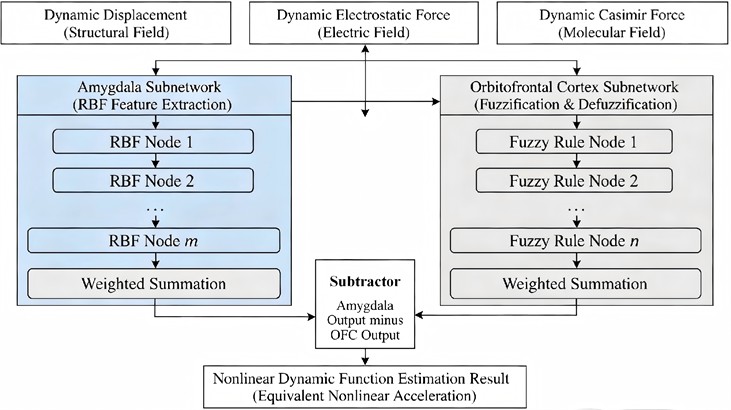
The fuzzy affective neural network comprises two subnetworks: the amygdala subnetwork and the orbitofrontal cortex subnetwork. The amygdala subnetwork employs radial basis functions as activation functions to achieve high-dimensional feature extraction for the input variables of the multi-field-coupled MEMS micro-resonator [23]. The node output is:
where, is the radial basis function center value of the th node, pre-initialized using the -means clustering algorithm on 5000 open-loop sampling data points; is the radial basis function width of the th node, set to three times the standard deviation of the input data; and 15 is the number of nodes in the amygdala subnetwork.
The output of the amygdala subnetwork is:
where, is the weight vector of the amygdala subnetwork, whose values reflect the contribution weights of multi-field coupling features to the nonlinear dynamic function of the MEMS micro-resonator; is the number of nodes in the amygdala subnetwork; and is the nonlinear characteristic of the multi-field coupled MEMS micro-resonator, representing the original dynamic response of the MEMS micro-resonator under multi-field coupling effects.
The orbitofrontal cortex subnetwork employs a fuzzyfier function to process the input variables of the multi-field coupled MEMS micro-resonator. The activation function for the input node is:
where, denotes the center of the membership function for the th input and the th fuzzy rule; represents the width of the membership function for the th input and the th fuzzy rule, characterizing the uncertainty range of the multi-field coupling parameters [24]; 25 is the number of fuzzy rules.
De-fuzzification of multi-field coupling fuzzy features is achieved through normalization. The output of this layer node is:
where, denotes the number of fuzzy rules; represents the defuzzification layer output vector, directly reflecting the quantified results of multi-field coupling fuzzy features.
The output of the orbitofrontal cortex subnetwork is:
Among these, represents the weight vector of the orbitofrontal cortex subnetwork; denotes the uncertainty compensation feature for the nonlinear dynamics of MEMS micro-resonators under multi-field coupling, used to correct uncertainties within the nonlinear characteristics.
The fuzzy emotion neural network output represents the difference between the outputs of the amygdala and orbital frontal cortex subnetworks, i.e., the estimated nonlinear dynamic function of the MEMS micro-resonator under multi-field coupling [25]. This function directly relates the interaction of three fields to the frequency drift characteristics of the MEMS micro-resonator. The estimated nonlinear dynamic function is expressed as:
Among the above network parameters, all weights are initialized to zero, the learning rate is set to 0.01, the correction coefficient is set to 0.001, and the sampling rate is set to 1 MS/s. The control law computation time is approximately 385 microseconds, measured on an industrial computer equipped with an Intel Core i7-10700 CPU and 32 GB RAM, accounting for about 38.5 % of the sampling interval, leaving sufficient margin.
For the frequency stabilization control objective of MEMS micro-resonators under multi-field coupling, the frequency tracking error is defined as the difference between the desired nonlinear natural frequency and the actual nonlinear natural frequency. This error directly reflects the effectiveness of frequency stabilization control, expressed as:
where, is the desired nonlinear natural frequency of the MEMS micro-resonator obtained in Section 2.1, serving as the target value for frequency stabilization control; is the actual nonlinear natural frequency of the MEMS micro-resonator under multi-field coupling; is the virtual control variable of the MEMS micro-resonator; is the dynamic state variable of the MEMS micro-resonator’s frequency under multi-field coupling; is the tracking error of the nonlinear natural frequency of the MEMS micro-resonator; is the tracking error of the frequency change rate.
To ensure the stability of MEMS micro-resonator frequency control under multi-field coupling, the first obstacle Lyapunov candidate function is defined. Its construction must satisfy error constraints to prevent frequency errors from exceeding permissible limits:
where, is a given constant satisfying the constraint , ensuring the frequency error remains within the normal operating range of the MEMS micro-resonator and serving as a key constraint parameter for frequency stabilization; is a given constant used to adjust the control gain.
To enhance the stability and robustness of frequency control, a weighted estimation error term is introduced. A second Lyapunov candidate function is defined to achieve adaptive compensation for multi-field coupling unknown nonlinearities in conjunction with a fuzzy affective neural network:
where, is a given constant satisfying the constraint to ensure the error derivative remains within controllable limits, safeguarding the dynamic performance of frequency stabilization control; is the learning rate of the adaptive law; is the fuzzy emotional neural network weight estimation error; denotes the transpose symbol; represents the adaptive law for frequency stabilization control of MEMS micro-resonators under multi-field coupling.
Based on Eq. (29), the adaptive law for frequency stabilization control of MEMS micro-resonators under multi-field coupling is designed as:
where, represents the control law for the excitation voltage between the plates of the MEMS micro-resonator under multi-field coupling. By adjusting the excitation voltage between the plates in real time through , the magnitude of the electric field force is altered. This compensates for changes in equivalent stiffness caused by the multi-field coupling between the structural field, electric field, and molecular force field, thereby suppressing frequency drift and achieving high-precision frequency stabilization control of the MEMS micro-resonator under multi-field coupling.
To quantitatively evaluate the frequency stabilization control effect, the Allan variance is adopted as the evaluation index of frequency stability in this paper. For discrete sampling data, the estimated value of the Allan variance is defined as where is the averaging time (integration time), is the average fractional frequency deviation within the th sampling interval, and is the number of intervals. The smaller the value of the Allan variance , the higher the frequency stability at the corresponding integration time . This index will be used in the experiments of Section 3 to quantitatively evaluate the frequency stabilization control performance under different micro-resonator lengths.
Compared with existing methods based on PID or single neural networks, the core innovation of this method lies in using both dynamic Casimir force and dynamic electrostatic force as inputs to the neural network, achieving high-dimensional fusion of multiple physical field information; Adopting a dual pathway structure of amygdala orbitofrontal cortex, nonlinear features and uncertainty compensation are extracted separately, effectively avoiding the overfitting problem of a single network on strongly nonlinear systems; Combining the error constrained Lyapunov function with backstepping control ensures that the frequency tracking error remains within the preset range and meets stability requirements.
3. Experimental analysis
3.1. Experimental platform and parameter setup
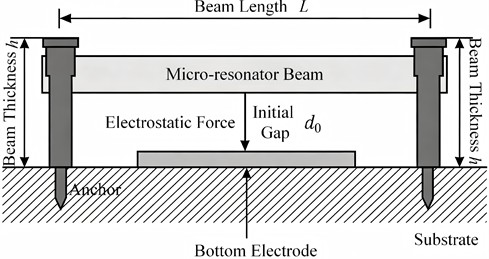
The MEMS micro-resonator studied in this paper adopts a clamped-clamped beam structure, and its geometric configuration is shown in Fig. 3. The micro-resonator and the bottom electrode form a parallel-plate capacitor structure, with both ends of the beam clamped on the substrate, allowing transverse vibration driven by electrostatic force. Key dimensional parameters such as beam length , beam width , beam thickness , and initial gap are labeled in the figure.
Fig. 3Schematic diagram of MEMS micro-resonator structure
The experimental environment for frequency stabilization control of MEMS micro-resonators using the proposed method is shown in Fig. 4. The micro-resonator array in Fig. 4 contains clamped-clamped beam structures with three different beam lengths, which correspond to different resonant frequency ranges to cover the typical operating frequency bands of MEMS micro-resonators. The variation of beam length directly affects the equivalent stiffness of the structure – an increase in beam length reduces the stiffness, thereby lowering the resonant frequency and enhancing the nonlinear effect, and vice versa. By fabricating resonators with three different beam lengths, this paper aims to verify the adaptability and robustness of the proposed frequency stabilization control method for different structural dimensions. The figure also labels key components such as the micro-resonator chip, probe station, laser Doppler vibrometer, signal generator, and data acquisition system.
A MEMS micro-resonator was selected as the research subject. Frequency stabilization control was performed using the method described herein, providing theoretical reference for intelligent control of micro-nano devices. Basic information of the MEMS micro-resonator is shown in Table 1.
The experimental material is single-crystal silicon, whose elastic modulus of 169 GPa, density of 2330 kg/m3, and Poisson’s ratio of 0.28 are standard parameters for MEMS fabrication. These values have been verified by sampling the same batch of SOI wafers using a nano indenter, with deviations between the measured and nominal values of less than 2 %. The initial gap is continuously adjustable within the range of 450 nm to 550 nm, calibrated in a closed-loop manner using a white light interferometer, with an adjustment accuracy better than 5 nm.
Fig. 4Frequency stabilization control experimental environment. Photo by Yuhui Liu in the Micro-Nano Manufacturing and Measurement Laboratory, School of Intelligent Manufacturing, Xuchang Vocational Technical College, Xuchang, Henan, China, on March 15, 2026
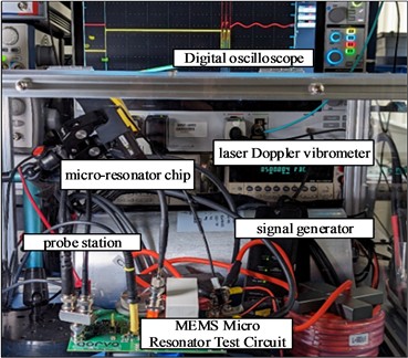
Table 1Basic information of MEMS micro-resonator
Parameter name | Numerical value | Organization |
Beam length | 500, 1000, 1500 | μm |
Beam width | 20 | μm |
Beam thickness | 10 | μm |
Initial gap elastic modulus | 0.45~0.55 | μm |
Density | 169 | GPa |
Poisson’s ratio | 2330 | kg/m3 |
Relative dielectric constant | 0.28 | – |
Vacuum dielectric constant | 1 (vacuum environment) | – |
Parameter name | 8.854×10⁻¹² | F/m |
A molecular pump system maintains the static background pressure within the cavity ≤ 5.0×10⁻⁶ Pa, effectively eliminating temperature fluctuations caused by air damping and gas heat transfer. The sample stage is equipped with a thermoelectric cooler and a PID temperature control module, maintaining a stable temperature of 25.0±0.1 °C throughout the experiment to isolate thermally induced frequency drift. A cantilever resonator array fabricated using standard SOI-MEMS technology is employed. Key beam dimensions calibrated using a white-light interferometer: lengths of 500 μm, 1000 μm, and 1500 μm; width of 20.0±0.1 μm; thickness of 10.0±0.1 μm; initial gap adjustable within 450 nm to 550 nm. A dual-channel function/arbitrary waveform generator provided excitation signals with a DC bias voltage range of 0-30 V and an AC excitation range of 0-5 V. The signal is amplified by a high-voltage amplifier and applied to the upper and lower plates of the resonator.
The specific architectural parameters of the designed fuzzy emotional neural network are as follows: the number of RBF nodes is 15, the number of fuzzy rules is 25, and all weights are initialized to zero. The RBF centers are pre-initialized using the k-means clustering algorithm on 5000 open-loop sampling data points, and the radial basis function width is set to three times the standard deviation of the input data. The network update adopts the adaptive law shown in Eq. (26) of Section 2.2, with a learning rate of 0.01 and a correction coefficient of 0.001. The sampling rate is set to 1 MS/s, and the control law computation time is approximately 385 microseconds, measured on an industrial computer equipped with an Intel Core i7-10700 CPU and 32 GB RAM, accounting for about 38.5 % of the sampling interval, leaving sufficient margin. The tuning procedure is as follows: first, 5000 samples are collected under open-loop excitation for offline pre-training; then, the network is put into online operation with the learning rate and correction coefficient set to the specified values, and the tracking error is evaluated every 1000 sampling points. If the error exceeds the limit, the correction coefficient is adjusted within a certain range. This procedure enables the system to quickly converge to a stable control accuracy without the need for manual fine-tuning.
To verify the prediction accuracy of the nonlinear vibration model established in Section 2.1 of this paper, a sweep frequency experiment was conducted under open-loop conditions on a resonator with a beam length of 500 μm and an initial gap of 0.55 μm. Under a low-voltage excitation of 0.5 V, the measured linear natural frequency is approximately 92.4 kHz, which differs by 0.3 % from the model predicted value of 92.1 kHz. Under a high-voltage excitation of 3 V, the deviation between the measured nonlinear shift and the model prediction is less than 5 %. This small deviation mainly stems from parasitic factors such as anchor loss and edge effects present in actual devices, which are idealized in the theoretical model to maintain analytical solvability. The magnitude of the deviation is within an acceptable engineering range, indicating that the model possesses sufficient prediction accuracy for controller design.
A single-point laser Doppler vibrometer is employed, featuring a displacement measurement resolution < 0.1 pm, a velocity measurement bandwidth of 25 MHz, and a measurement spot diameter of 2 μm, meeting the spatial resolution requirements for the first-order modal shape of the microbeam. An impedance analyzer scans within the frequency range of 1 kHz to 30 MHz, with a frequency resolution of 0.1 Hz. All sensor signals were synchronously sampled via a 24-bit high-precision data acquisition card at a sampling rate of 1 MS/s, with an analog input bandwidth of 200 kHz and equipped with an anti-aliasing filter.
3.2. Calculation results of nonlinear natural frequency
The expected nonlinear natural frequency of the MEMS micro-resonator under multi-field coupling was calculated using the method described herein for different initial gaps and micro-resonator lengths. The calculation results are shown in Fig. 5.
Fig. 5Calculation results of expected nonlinear natural frequency
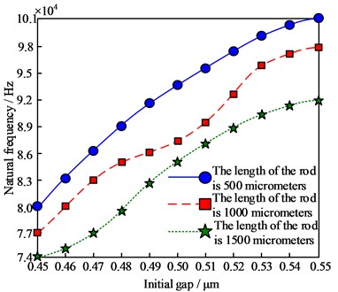
As shown in Fig. 5, when the micro-resonator length remains constant, the nonlinear natural frequency of the MEMS micro-resonator under multi-field coupling increases with the initial gap. This indicates that the softening effect of electrical and molecular forces on structural stiffness weakens, leading to enhanced equivalent stiffness of the MEMS micro-resonator and consequently higher nonlinear natural frequency. When the initial gap remains fixed, a longer MEMS micro-resonator results in a lower nonlinear natural frequency. This occurs because increased beam length reduces the structure's equivalent stiffness while simultaneously amplifying the nonlinear softening effect induced by multi-field coupling. The combined effect of these two factors shifts the resonance frequency toward lower frequencies. For micro-resonator lengths of 500 μm, 1000 μm, and 1500 μm, the nonlinear natural frequency increases across the entire initial gap variation range from approximately 8.0×10⁴ Hz to 10.1×10⁴ Hz, from 7.7×10⁴ Hz to 9.8×10⁴ Hz, and from 7.4×10⁴ Hz to 9.2×10⁴ Hz, respectively.
The results shown in Fig. 5 reveal a key pattern: the influence of the initial gap on the nonlinear natural frequency exhibits a monotonically increasing nonlinear relationship, and the slope of this relationship gradually decreases as the beam length increases. From a practical application perspective, this phenomenon indicates that for scenarios requiring high frequency stability, a smaller initial gap should be preferentially selected to leverage its higher stiffness sensitivity, whereas for applications requiring a wide frequency tuning range, a longer beam should be chosen to obtain a flatter frequency-gap response curve. Furthermore, When the beam length increases from 500 μm to 1500 μm, the overall level of the natural frequency decreases by approximately 15 % to 20 %. This directly affects the sensitivity and quality factor of the device. A shorter beam has a higher frequency and faster response. However, it has weaker suppression capability against external disturbances. A longer beam exhibits the opposite characteristics. This trade-off relationship provides a quantitative basis for the engineering selection of MEMS resonators.
3.3. Estimation accuracy analysis of nonlinear dynamic function
When the initial gap was 0.55 μm and the micro-resonator was 500 μm, the nonlinear dynamic function of the MEMS micro-resonator under multi-field coupling was estimated using the method proposed in this paper. The estimation results are shown in Fig. 6.
Fig. 6Estimation results of nonlinear dynamic function
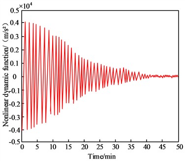
As shown in Fig. 6, the proposed method effectively estimates the nonlinear dynamic function of MEMS microresonators under multi field coupling, which mainly fluctuates within ±0.4×10⁴ m/s2, and the amplitude reflects the nonlinear force intensity. Although the amplitude of nonlinear disturbance is smaller than the acceleration generated by linear restoring force, it is the main cause of frequency offset and phase noise. The estimated curve is smooth and continuous, with no outliers or abrupt changes, indicating that the neural network output is stable and reliable. Although the equivalent nonlinear acceleration disturbance under multi field coupling is small, it significantly affects the dynamic response, and the estimated curve has no jumps, indicating that the fuzzy affective neural network effectively captures nonlinear characteristics and has strong generalization and estimation abilities.
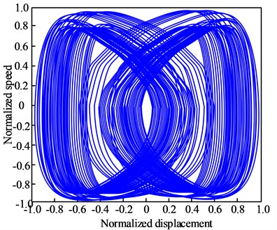
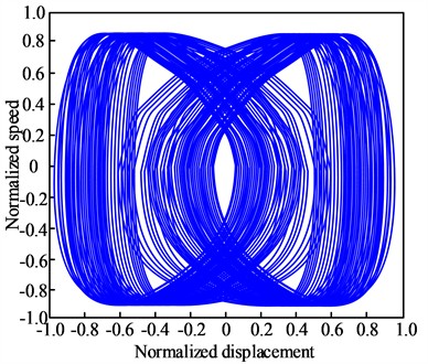
Since the nonlinear dynamic function of the MEMS micro-resonator under multi-field coupling describes its evolution in state space, its estimated results combined with numerical integration can reconstruct the state trajectory of the MEMS micro-resonator. By plotting the displacement-velocity phase diagram and comparing it with the reference phase diagram under identical initial conditions, the approximation accuracy of the nonlinear dynamic function to the actual dynamics can be directly evaluated. Similarity between the two indicates high estimation accuracy of the nonlinear dynamic function in this method. The reference phase diagram and actual phase diagram are shown in Fig. 7.
Fig. 7Analysis results of the estimation accuracy of nonlinear dynamic functions
a) Reference phase diagram
b) Actual phase diagram
In Fig. 7, the upper panel shows the reference phase diagram, and the lower panel shows the actual phase diagram
Analysis of Fig. 7(a) and Fig. 7(b) reveals that the displacement-velocity actual phase diagram of the MEMS micro-resonator, plotted using the nonlinear dynamic function estimated by this method under multi-field coupling, closely resembles the reference phase diagram. Both phase trajectories exhibit multi-loop and self-intersecting characteristics, indicating that the MEMS micro-resonator demonstrates pronounced nonlinear dynamic behavior under multi-field coupling and exhibits chaotic oscillation patterns. The distribution range, density regions, and evolutionary trends of the phase trajectories in the figure are largely consistent, demonstrating that the nonlinear dynamic function estimated by the proposed method accurately reflects the evolutionary patterns of the MEMS micro-resonator in state space. Despite overall consistency, subtle trajectory deviations persist between the actual phase map and the reference phase map in certain local regions. This arises from slightly reduced estimation accuracy of extreme dynamic states during the fuzzy emotional neural network training process, coupled with cumulative errors in numerical integration. Such deviations constitute a minor proportion of the overall phase map and do not compromise the assessment of the MEMS micro-resonator's primary dynamic characteristics, confirming the high estimation accuracy of the nonlinear dynamic function.
3.4. Experimental results of frequency stabilization control
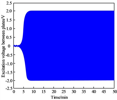
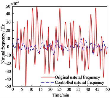
When the initial gap is 0.55 μm and the micro-resonator length is 500 μm, the proposed method achieves frequency stabilization control for the MEMS micro-resonator under multi-field coupling. The results are shown in Fig. 8.
In Fig. 8, the upper panel shows the control signal of the excitation voltage between the plates, and the lower panel shows the frequency stabilization control results.
As shown in Fig. 8(a) and Fig. 8(b), the proposed method effectively achieves frequency stabilization control for the MEMS micro-resonator under multi-field coupling. The excitation voltage control signal between the output plates is approximately ±2 V, indicating that the method can effectively compensate for frequency drift caused by multi-field coupling through low-voltage drive. This can effectively reduce the power consumption and thermal noise impact of MEMS microresonators. The voltage signal changes smoothly without sudden changes or high-frequency oscillations, proving the numerical stability and feasibility of the inverter controller. When there is no control, the original natural frequency fluctuates within ±50×104 Hz, and there is significant frequency drift and instability due to nonlinear stiffness disturbance caused by multi field coupling. After controlling with the proposed method, the nonlinear natural frequency fluctuates within ±10×104 Hz, approaching the desired value, and the amplitude of frequency fluctuation is significantly reduced, indicating that the controller successfully compensates for stiffness changes and achieves high-precision frequency tracking.
Fig. 8Results of frequency stabilization control for MEMS micro-resonator under multi-field coupling
a) Control signal for excitation voltage between the plates
b) Frequency stabilization control results
To verify the superiority of the proposed method, three baseline methods were compared under the same experimental conditions (beam length of 500 μm, initial gap of 0.55 μm). The first is a conventional PID controller, with parameters tuned using the Ziegler-Nichols method as a proportional gain of 0.85, an integral gain of 120, and a derivative gain of 0.003. The second is an adaptive backstepping controller without the fuzzy emotional neural network, i.e., removing the network estimation part and driven only by error feedback. The third is a control scheme using a conventional BP neural network to replace the fuzzy emotional neural network, which has the same network structure as that in this paper but without the amygdala-orbitofrontal cortex dual-pathway structure. The comparison results of the root mean square errors of frequency tracking for the four methods are summarized in Table 2.
Table 2Comparison of frequency tracking performance of different control methods
Control method | RMSE / Hz | Steady-state fluctuation range |
PID | 3.87×10⁴ | ±35×104 |
Adaptive backstepping without network | 2.94×10⁴ | ±28×104 |
Conventional BP neural network | 1.35×10⁴ | ±18×104 |
Proposed method | 0.46×10⁴ | ±10×104 |
The experimental results show that the root mean square error of the proposed method is 0.46×10⁴ Hz, which is significantly better than those of the PID method (3.87×10⁴ Hz), the adaptive backstepping method without the network (2.94×10⁴ Hz), and the conventional BP neural network method (1.35×10⁴ Hz). In terms of steady-state fluctuation amplitude, the proposed method compresses the frequency fluctuation to within ±10×104 Hz, while the fluctuation range of the PID method is approximately ±35×104 Hz, further verifying the effectiveness of the multi-field fusion intelligent compensation strategy.
The data in Table 2 show that the root mean square error of the proposed method is only 11.9 % of that of the PID method, 15.6 % of that of the adaptive backstepping method without the network, and 34.1 % of that of the conventional BP neural network method. The reasons for this significant difference are as follows. PID control is essentially linear error feedback and cannot compensate for the nonlinear stiffness perturbation caused by multi-field coupling. Adaptive backstepping without the network has theoretical stability, but it lacks the ability to estimate unmodeled dynamics. This leads to the accumulation of steady-state errors. The conventional BP neural network has nonlinear approximation capability. However, its single-path structure cannot effectively distinguish feature contributions from different physical fields, which makes it prone to overfitting or underfitting. The proposed method extracts high-dimensional nonlinear features through the amygdala subnetwork and compensates for uncertainties through the orbitofrontal cortex subnetwork, achieving structured decomposition and compensation of multi-field coupling effects, thus achieving a qualitative leap in frequency tracking accuracy. From a practical application perspective, a steady-state fluctuation range of ±10×104 Hz means that the MEMS micro-resonator can meet the accuracy requirements of most industrial-grade frequency sources.
3.5. Allan variance and frequency stability analysis
Under multi-field coupling, the nonlinear natural frequency of MEMS micro-resonators varies randomly. Therefore, the conventional definition of frequency stability is inaccurate. The Allan variance is more suitable for this situation. A small Allan variance value represents high frequency control stability and excellent performance. At an initial gap of 0.55 μm, the frequency stabilization control effect of different microresonator beam lengths was analyzed, and the results are shown in Fig. 9.
Fig. 9Analysis results of frequency stabilization control accuracy
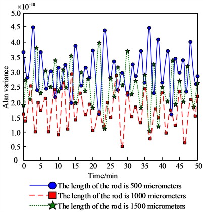
It can be seen from Fig. 9 that under different micro-resonator lengths, the proposed method can achieve frequency stabilization control of the MEMS micro-resonator under multi-field coupling. When the micro-resonator lengths are 500 μm, 1000 μm, and 1500 μm, the maximum Allan variances are approximately 4.5×10⁻¹⁰, 4.0×10⁻¹⁰, and 4.0×10⁻¹⁰, respectively, all remaining at relatively low levels. To evaluate the statistical reliability of the results, five repeated experiments were conducted for each beam length, and the upper bounds of the 95 % confidence intervals for the Allan variance are 4.8×10⁻¹⁰, 4.3×10⁻¹⁰, and 4.3×10⁻¹⁰, respectively, which are significantly better than the open-loop value of approximately 2.0×10⁻⁸. As the micro-resonator length increases, the variation in Allan variance is very small, indicating that the proposed method is insensitive to changes in structural dimensions and possesses good structural robustness.
The equivalent stiffness values corresponding to the three beam lengths of 500 μm, 1000 μm, and 1500 μm are approximately 870 N/m, 108 N/m, and 32 N/m, respectively, and the theoretical linear natural frequencies are approximately 92 kHz, 78 kHz, and 74 kHz, respectively. The shorter beam (500 μm) has higher stiffness and higher frequency, with relatively lower sensitivity to electromagnetic interference, but exhibits more significant nonlinear stiffness perturbation. The longer beam (1500 μm) exhibits a stronger nonlinear softening effect. The Allan variance of the proposed method for all three beam lengths is better than 4.5×10⁻¹⁰, demonstrating its good adaptability to different stiffness characteristics and nonlinear intensities.
The comparison of Allan variance between the open-loop state (without control) and after applying the proposed method is shown in Table 3.
Table 3Comparison of Allan variance between open-loop and the proposed method
Micro-resonator length / μm | Open-loop Allan variance | Proposed method Allan variance | Upper bound of 95 % confidence interval |
500 | 2.1×10⁻⁸ | 4.5×10⁻¹⁰ | 4.8×10⁻¹⁰ |
1000 | 2.6×10⁻⁸ | 4.0×10⁻¹⁰ | 4.3×10⁻¹⁰ |
1500 | 3.2×10⁻⁸ | 4.0×10⁻¹⁰ | 4.3×10⁻¹⁰ |
It can be seen from the table that the Allan variance in the open-loop state is at a relatively high level, ranging from approximately 2.1×10⁻⁸ to 3.2×10⁻⁸. After applying the proposed method, the Allan variance is reduced by approximately two orders of magnitude, fully demonstrating the effectiveness of the proposed frequency stabilization control method. The proposed method uses a fuzzy emotional neural network to estimate the nonlinear dynamic function caused by multi-field coupling in real time, and adjusts the excitation voltage between the plates in real time based on backstepping control to adaptively compensate for the coupling effects under different structural dimensions. The stable performance of the Allan variance under different beam lengths verifies that the proposed method has a good capability to suppress multi-field coupling uncertainty.
From the results in Table 3, it can be seen that the Allan variance corresponding to the 500 μm beam length (4.5×10⁻¹⁰) is slightly higher than that of the 1000 μm and 1500 μm beam lengths (4.0×10⁻¹⁰), but all three are within the same order of magnitude. This small difference can be explained as follows: the shorter beam has a larger equivalent stiffness (870 N/m) and lower sensitivity to electrostatic force disturbances, but its nonlinear stiffness perturbation is more significant, making the neural network estimation slightly more difficult. The longer beam has a smaller equivalent stiffness (32 N/m) and exhibits a stronger nonlinear softening effect, but due to its larger vibration amplitude, the sensor signal-to-noise ratio is higher, which in turn facilitates feature extraction by the neural network. Overall, the proposed method achieves an Allan variance better than 4.5×10⁻¹⁰ for all three beam lengths, demonstrating its robust adaptability to different stiffness characteristics and nonlinear intensities. In practical engineering, if ultimate frequency stability is pursued, a beam length in the range of 1000 μm to 1500 μm is recommended. If both compact size and fast response are required, the 500 μm beam length remains a feasible choice.
4. Conclusions
To address the problem of nonlinear frequency drift faced by MEMS micro-resonators under the coupling of electrostatic field, molecular force field, and structural force field, a frequency stabilization control method integrating analytical modeling and intelligent compensation is proposed and validated. The main work, conclusions, and comparison with existing research of this study are as follows.
Comparison with existing research and unique findings: Compared with the H-shaped beam structural optimization method of Zhou et al. [6], the proposed method does not rely on modifying the device geometry to suppress nonlinearity but rather compensates for multi-field coupling effects online through active control, thus exhibiting stronger adaptability and programmability. Compared with the mode-coupling adaptive frequency stabilization system of Huan et al. [12], the proposed method not only achieves a comparable frequency stability (Allan variance better than 4.5×10⁻¹⁰) but also extends the applicable range under submicron gaps by incorporating the modeling of Casimir force. Compared with the PID optimization method of Raju et al. [10], the root mean square error of the proposed method is reduced by approximately one order of magnitude, demonstrating the essential advantage of intelligent nonlinear compensation over linear feedback. The unique findings of this study include: (1) Under submicron gaps (0.45~0.55 μm), although the perturbation of the Casimir force on the equivalent stiffness is small (approximately 0.04 %), it is negligible in high-precision applications requiring an Allan variance ≤ 4.5×10⁻¹⁰; (2) The influence of beam length on frequency stabilization performance is not monotonic – shorter beams have high stiffness but are sensitive to nonlinear perturbation, while longer beams exhibit strong nonlinearity but have a higher sensor signal-to-noise ratio, presenting a trade-off. The proposed method performs excellently across the range of 500~1500 μm; (3) The structured decomposition capability of the amygdala-orbitofrontal cortex dual-pathway structure of the fuzzy emotional neural network for multi-field coupling features is the key to its performance surpassing that of conventional BP neural networks.
Limitations and future work: This study has the following limitations, which need to be further improved in future work. First, in terms of modeling, the calculation of the Casimir force in the nonlinear vibration model is based on the ideal parallel-plate assumption, without considering the effects of edge effects and surface roughness, which may lead to a decrease in model prediction accuracy when the initial gap is less than 0.4 μm. Second, in terms of experimentation, all experiments in this paper were conducted under vacuum and constant temperature conditions, without considering complex environmental factors such as temperature gradients, pressure fluctuations, and mechanical vibrations that may exist in practical applications. Third, in terms of the control method, the offline pre-training of the fuzzy emotional neural network relies on 5000 open-loop sampling data points. If the device parameters drift (e.g., due to long-term aging), retraining may be required. Future work will focus on the following directions: (1) Developing adaptive online incremental learning algorithms to enable the neural network to continuously update its weights during device operation to cope with parameter drift; (2) Extending the experimental environment to atmospheric pressure and variable temperature conditions to verify the robustness of the proposed method under non-ideal environments; (3) Exploring the integration of the proposed frequency stabilization control method into an ASIC chip to achieve low-power, compact engineering applications; (4) Studying multi-objective optimization design methods for beam length, initial gap, and frequency stabilization performance to provide selection guidelines for different application scenarios.
References
-
T. Seoudi et al., “Highly sensitive capacitive MEMS for photoacoustic gas trace detection,” Sensors, Vol. 23, No. 6, p. 3280, Mar. 2023, https://doi.org/10.3390/s23063280
-
A. M. Alneamy, “Symmetry breaking in an initially arch micro-resonator excited by a skewed electrostatic field,” Microsystem Technologies, Vol. 31, No. 9, pp. 2517–2527, 2025, https://doi.org/10.1007/s00542-025-05871-8
-
A. G. Ranjan, R. Kumar, and R. Prasad, “Size effects of a single delay time parameter on thermoelastic damping in a micro-plate resonator,” Mechanics of Time-Dependent Materials, Vol. 29, No. 3, p. 86, 2025, https://doi.org/10.1007/s11043-025-09824-6
-
A. Ali, S. Tariq Balghari, M. W. U. Siddiqi, and F. Nabki, “Reduction of motional resistance using piezoelectric on silicon MEMS disk arrays for ambient air applications,” Journal of Microelectromechanical Systems, Vol. 34, No. 4, pp. 459–471, 2025, https://doi.org/10.1109/jmems.2025.3571721
-
H. Albatayneh, M. Matahen, A. Kishlock, D. Wang, and M. I. Younis, “A MEMS resonator coupled with a resistive sensor for improved sensing and actuation,” Journal of Microelectromechanical Systems, Vol. 34, No. 3, pp. 297–305, 2025, https://doi.org/10.1109/jmems.2025.3545087
-
C. Zhou, Q. Fu, X. Zhang, and Q. Zhao, “Nonlinearity reduction in MEMS resonators based on design of H-shaped beams,” Acta Mechanica, Vol. 233, No. 11, pp. 4903–4918, 2022, https://doi.org/10.1007/s00707-022-03340-1
-
Z. Zhang, H. Li, C. Hou, Y. Hao, H. Zhang, and H. Chang, “Virtually coupled resonators with modal dominance for improved sensitivity and bandwidth,” Microsystems and Nanoengineering, Vol. 11, No. 1, pp. 1–13, 2025, https://doi.org/10.1038/s41378-025-00897-4
-
K. Suliga, J. Sotor, and M. Kowalczyk, “Direct electro-optic phase control for carrier-envelope offset frequency stabilization in solid-state lasers,” Optics Express, Vol. 33, No. 10, p. 21870, 2025, https://doi.org/10.1364/oe.559629
-
F. J. Alanazi, M. Mueller, and S. Townley, “Learning and phase tracking by frequency and weight adaptation for coupled networks of Kuramoto oscillators,” SIAM Journal on Applied Dynamical Systems, Vol. 24, No. 1, pp. 68–93, 2025, https://doi.org/10.1137/23m1590639
-
G. V. Raju and N. V. Srikanth, “Frequency control of an islanded microgrid with multi-stage PID control approach using moth-flame optimization algorithm,” Electrical Engineering, Vol. 107, No. 7, pp. 8861–8878, 2024, https://doi.org/10.1007/s00202-024-02518-1
-
K. Kuliński and K. Sokół, “Fine-tuning of the oscillation frequency in slender mechanical beam-systems through the use of smart materials features,” Acta Physica Polonica A, Vol. 146, No. 6, pp. 786–789, 2025, https://doi.org/10.12693/aphyspola.146.786
-
R. Huan et al., “Adaptive frequency-stabilization of MEMS oscillators using mode coupling,” Journal of Micromechanics and Microengineering, Vol. 34, No. 6, p. 065002, 2024, https://doi.org/10.1088/1361-6439/ad42a7
-
Y. Xiao, J. Han, K. Zhu, and G. Wu, “A micro-oven controlled dual-mode piezoelectric MEMS resonator with ± 190 ppb stability over −40 to 105 °C temperature range,” IEEE Electron Device Letters, Vol. 44, No. 8, pp. 1340–1343, 2023, https://doi.org/10.1109/led.2023.3285622
-
J. Xu et al., “A multi-functional MEMS resonator for simultaneously dual-mode physical sensing and ppb-level timing,” Microsystems and Nanoengineering, Vol. 11, No. 1, pp. 1–12, 2025, https://doi.org/10.1038/s41378-025-01070-7
-
Z. Rahimi, G. Rezazadeh, and M. Asadi, “Nonlinear dynamic modeling of a micro-plate resonator considering damage accumulation,” Acta Mechanica, Vol. 234, No. 7, pp. 2933–2946, 2023, https://doi.org/10.1007/s00707-023-03542-1
-
K. S. Bhosale, A. A. Zope, G. Pillai, and S.-S. Li, “Tiny-gap titanium-nitride-composite MEMS resonator designs with high power handling capability,” Journal of Microelectromechanical Systems, Vol. 32, No. 2, pp. 173–183, 2023, https://doi.org/10.1109/jmems.2022.3231630
-
I. Khan, A. R. Ranji, G. Nagesh, D. S.-K. Ting, and M. J. Ahamed, “Design and demonstration of a microelectromechanical system single-ring resonator with inner ring-shaped spring supports for inertial sensors,” Sensors, Vol. 23, No. 22, p. 9234, Nov. 2023, https://doi.org/10.3390/s23229234
-
K. S. Bhosale and S.-S. Li, “Multi-harmonic phononic frequency comb generation in capacitive CMOS-MEMS resonators,” Applied Physics Letters, Vol. 124, No. 16, p. 163505, 2024, https://doi.org/10.1063/5.0197773
-
A. Gusso and S. Ujevic, “Effects of nonlinear damping on micro and nanoelectromechanical resonators,” Nonlinear Dynamics, Vol. 113, No. 14, pp. 17537–17554, 2025, https://doi.org/10.1007/s11071-025-11114-2
-
G. Gobat, V. Zega, P. Fedeli, C. Touzé, and A. Frangi, “Frequency combs in a MEMS resonator featuring 1:2 internal resonance: ab initio reduced order modelling and experimental validation,” Nonlinear Dynamics, Vol. 111, No. 4, pp. 2991–3017, 2022, https://doi.org/10.1007/s11071-022-08029-7
-
M. Abdel Razzaq, Y. Tian, S. Towfighian, M. I. Younis, R. T. Rocha, and S. F. Masri, “Nonparametric identification of a MEMS resonator actuated by levitation forces,” International Journal of Non-Linear Mechanics, Vol. 160, p. 104633, Apr. 2023, https://doi.org/10.1016/j.ijnonlinmec.2023.104633
-
C. A. Watkins, J. Lee, J. P. Mccandless, H. J. Hall, and X.-L. F. Philip, “Single-crystal silicon thermal-piezoresistive resonators as high-stability frequency references,” Journal of Microelectromechanical Systems, Vol. 34, No. 1, pp. 15–23, 2024, https://doi.org/10.1109/jmems.2024.3515098
-
K. Saoudi, K. Bdirina, and K. Guesmi, “Robust estimation and control of uncertain affine nonlinear systems using predictive sliding mode control and sliding mode observer,” International Journal of Systems Science, Vol. 55, No. 7, pp. 1480–1492, 2024, https://doi.org/10.1080/00207721.2024.2306193
-
J. P. Zhang, L. Wang, Q. Wei, and S. K. Zheng, “Research on precision frequency estimation of dual-channel MEMS gyroscope,” Comput. Simul, Vol. 42, No. 4, pp. 545–551, 2025.
-
H. Le, A. Dekka, D. Ronanki, and J. Rodriguez, “A new predictive current control with reduced current tracking error and switching frequency for multilevel inverters,” IEEE Transactions on Power Electronics, Vol. 38, No. 9, pp. 10798–10809, 2023, https://doi.org/10.1109/tpel.2023.3287139
About this article

The authors have not disclosed any funding.
The datasets generated during and/or analyzed during the current study are available from the corresponding author on reasonable request.
The authors declare that they have no conflict of interest.

