Abstract
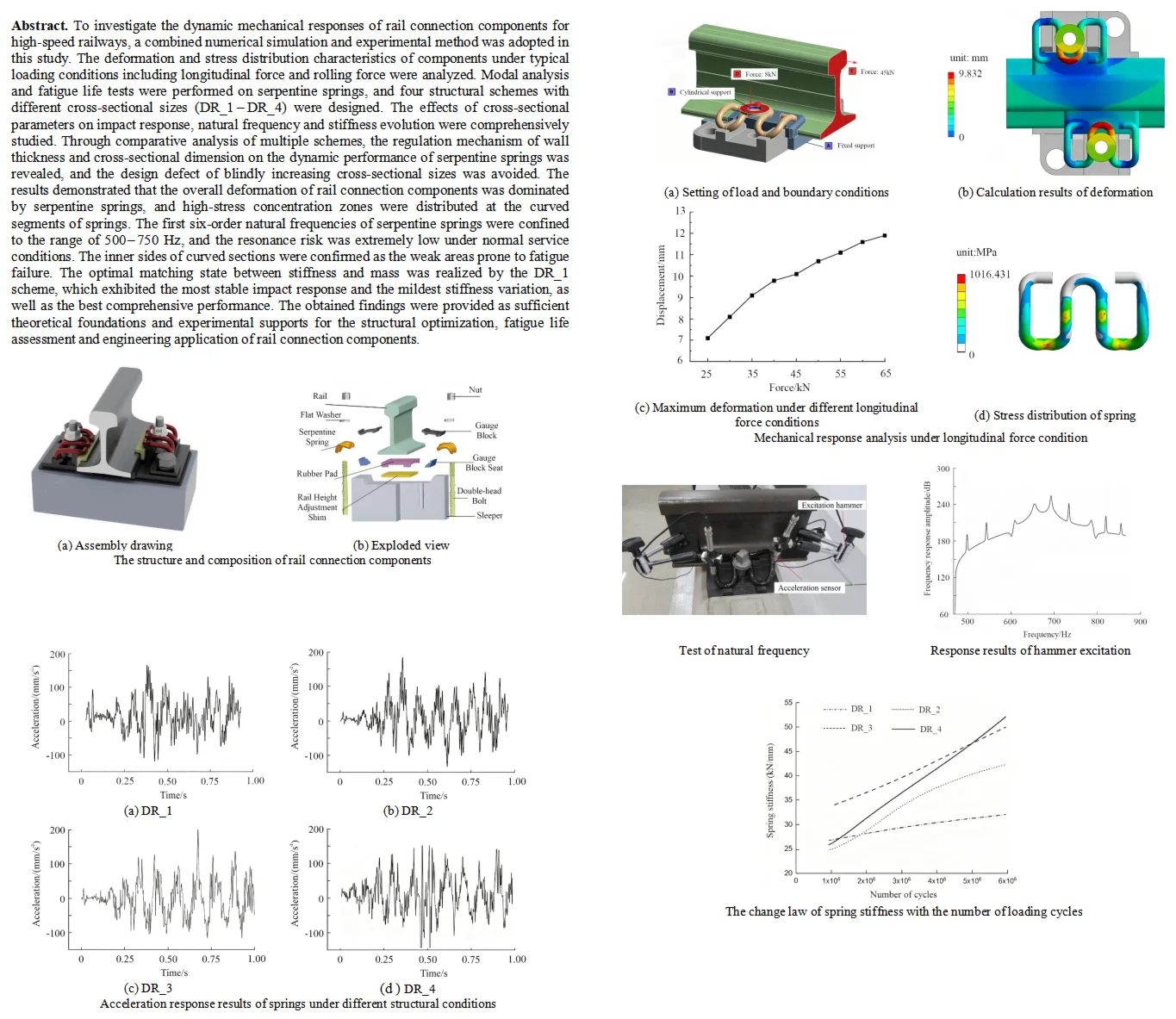
To investigate the dynamic mechanical responses of rail connection components for high-speed railways, a combined numerical simulation and experimental method was adopted in this study. The deformation and stress distribution characteristics of components under typical loading conditions including longitudinal force and rolling force were analyzed. Modal analysis and fatigue life tests were performed on serpentine springs, and four structural schemes with different cross-sectional sizes (DR_1-DR_4) were designed. The effects of cross-sectional parameters on impact response, natural frequency and stiffness evolution were comprehensively studied. Through comparative analysis of multiple schemes, the regulation mechanism of wall thickness and cross-sectional dimension on the dynamic performance of serpentine springs was revealed, and the design defect of blindly increasing cross-sectional sizes was avoided. The results demonstrated that the overall deformation of rail connection components was dominated by serpentine springs, and high-stress concentration zones were distributed at the curved segments of springs. The first six-order natural frequencies of serpentine springs were confined to the range of 500-750 Hz, and the resonance risk was extremely low under normal service conditions. The inner sides of curved sections were confirmed as the weak areas prone to fatigue failure. The optimal matching state between stiffness and mass was realized by the DR_1 scheme, which exhibited the most stable impact response and the mildest stiffness variation, as well as the best comprehensive performance. The obtained findings were provided as sufficient theoretical foundations and experimental supports for the structural optimization, fatigue life assessment and engineering application of rail connection components.
Highlights
- A finite element model of rail connection components considering both accuracy and efficiency is constructed.
- The dynamic response laws of rail connection components under different load conditions are systematically analyzed, and the weak links of serpentine spring failure are clarified, providing an accurate basis for fatigue life evaluation.
- An optimization idea of serpentine spring cross-section based on stiffness-mass matching is proposed.
1. Introduction
As one of the important components of the transportation system, the operational stability of high-speed railways is directly related to traffic safety and transportation efficiency [1]. As key supports of the track system, rail connection components are tasked with fixing rails, transmitting loads, and buffering vibrations. As the core elastic element in this system, the mechanical properties, dynamic response, and fatigue reliability of the serpentine spring directly determine the service quality of the entire track system. Currently, with the increase in the operating speed of high-speed railways, the impact load between the wheel and rail has increased significantly. Rail connection components are required to bear complex dynamic loads, which are prone to problems such as excessive vibration and fatigue failure, seriously affecting the long-term stable operation of the track system [2, 3]. The exploration of the dynamic response laws of high-speed railway rail connection components and the modal and fatigue characteristics of serpentine springs can clarify the regulatory mechanism of cross-sectional parameters on spring performance, provide a reliable theoretical basis and experimental support for the structural optimization, fatigue life evaluation, and engineering application of rail connection components, effectively reduce the failure risk of the track system, and improve the safety and durability of high-speed railway operation. Representative studies on rail vibration include: Sun [3] constructed a 2.5-dimensional finite element BEM model to simulate and analyze the vibration of rail structures in response to wheel rail interactions. The load response results under specific conditions were obtained, and the accuracy of the simulation model was confirmed through on-site measurements. Ren [4] determined the wave wear characteristics and natural frequency of the elastic clip track, established a prediction model to reveal the interaction and key role between wheelsets, and estimated the influence of speed changes and bogie wheelbase on vibration. Bhore [5] conducted research on vibration near trains, analyzed the FTA limits of surrounding components, and verified that the natural frequency and induced vibration are within the same frequency range. Plekhanov [6] considered the vibration of steel rails under electromagnetic force, and analyzed the vibration of steel rails by combining the fourth-order partial differential equation in coordinates with the second-order partial differential equation. Using the method of mode superposition, the analytical solution of the equation was obtained. Knuth [7] established finite element and boundary element models for continuously supported steel rails to study the effect of rail section deformation on acoustic radiation, and proposed a new interpolation strategy to significantly reduce solution time by interpolating element coefficient vectors.
Most existing studies focus on the performance analysis of components under a single load condition, and there is insufficient systematic research on the differences in dynamic response, modal characteristics, and fatigue life of serpentine springs with different cross-sectional dimensions, which is difficult to meet the needs of structural optimization and safety guarantee in engineering practice. Therefore, targeted experimental and numerical analysis research is urgently needed. To this end, this study focuses on high-speed railway rail connection components and serpentine springs. Firstly, a three-dimensional finite element model of rail connection components is established based on the actual engineering fastener system, and the reliability of the model is verified through static loading tests. Secondly, the deformation, stress distribution, and dynamic response laws of rail connection components under typical load conditions such as longitudinal force and rolling force are analyzed. Thirdly, modal analysis and fatigue life tests of the serpentine spring are carried out to clarify its modal characteristics, fatigue failure location, and life-influencing factors. Finally, four sets of serpentine spring schemes with different cross-sectional dimensions are designed to study the influence of cross-sectional parameters on impact response, natural frequency, and stiffness evolution, and the optimal cross-sectional design scheme is proposed.
The innovations of this study are mainly reflected in three aspects: (1) A finite element model of rail connection components considering both accuracy and efficiency is constructed. Through experimental verification, accurate matching between numerical simulation and engineering practice is achieved, solving the problem that traditional models have large deviations from actual working conditions. (2) The dynamic response laws of rail connection components under different load conditions are systematically analyzed, and the weak links of serpentine spring failure are clarified, providing an accurate basis for fatigue life evaluation. (3) An optimization idea of serpentine spring cross-section based on stiffness-mass matching is proposed. Through multi-scheme comparison, the regulatory mechanism of wall thickness and cross-sectional dimensions on spring dynamic performance is clarified, avoiding the design misunderstanding of blindly increasing cross-sectional dimensions, and providing a new technical path for the structural optimization of serpentine springs.
2. Analysis of dynamic response characteristics
2.1. The composition and working principle
The rail connection components (rail fastening system) for high-speed railways consist of a hierarchically assembled set of mechanical parts, each performing a distinct structural or functional role to secure the steel rail to the sleeper and maintain track geometry, as shown in Fig. 1. At the base, the sleeper serves as the primary foundation, with double-headed bolts embedded in its rail-bearing groove to anchor the entire system and transfer loads. On top of the sleeper, the rail height adjustment shim enables precise vertical tuning of the rail elevation, compensating for construction deviations and operational settlement to ensure rail surface smoothness. Above this shim, the rubber pad acts as a critical elastomeric element, absorbing wheel-rail impact energy, reducing track stiffness, and mitigating vibration transmission. The lateral constraint system is formed by the gauge block seat and gauge block: the seat provides a stable positioning reference, while the gauge block directly abuts the rail base to control track gauge and prevent lateral rail displacement under train-induced horizontal forces. At the top, the serpentine spring, flat washer, and nut constitute the vertical clamping mechanism: tightening the nut compresses the serpentine spring, which in turn exerts a sustained, elastic fastening force on the rail head’s lower jaw, pressing the rail firmly against the rubber pad.
Fig. 1The structure and composition of rail connection components
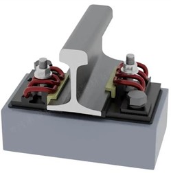
a) Assembly drawing
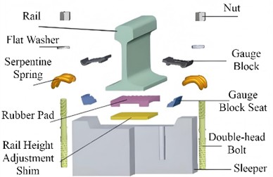
b) Exploded view
The working principle of the fastening system relies on the coordinated interaction of these components to achieve stable rail fixation, load transfer, dynamic adaptation, and vibration attenuation. Under static and dynamic train loads, the clamping force from the preloaded serpentine spring secures the rail, while vertical wheel loads are transmitted sequentially from the rail through the rubber pad, height adjustment shim, and finally to the sleeper via the double-headed bolt. The serpentine spring’s inherent elasticity allows it to accommodate rail deformations caused by transient train loads, eliminating stress concentration that would occur with rigid connections. Meanwhile, the rubber pad undergoes controlled compression to dissipate impact energy and reduce vibration, protecting both the track structure and train components from excessive fatigue. The gauge block and seat maintain the track’s lateral geometry, preventing rail shift during curve traversal or braking, while the height adjustment shim ensures long-term track smoothness. Collectively, these mechanisms guarantee the system’s reliability, stability, and durability under the repeated and complex dynamic loads of high-speed railway operation. The rigid lateral constraint system formed by the gauge block and gauge block seat can precisely control the track gauge, resist the centrifugal force generated when trains pass through curves and the lateral force induced by wheel-rail hunting motion, and prevent track gauge widening that would endanger driving safety. The rubber pad absorbs wheel-rail impact energy through its own elastic deformation, achieving vibration and noise reduction, while optimizing the track stiffness matching and reducing damage to the lower foundation caused by wheel-rail interaction forces. The double-headed bolt performs the anchoring function of the entire system, transmitting the vertical wheel load, lateral centrifugal force, longitudinal traction force and braking force borne by the rail connection system. The loads on this rail connection system exhibit significant multi-directional coupling, impact, and alternating fatigue characteristics. During its long-term service, it must simultaneously withstand static wheel loads and dynamic impact loads from trains, lateral centrifugal forces in curved sections, and longitudinal forces generated by train traction and braking.
3. Establishment and verification of finite element model
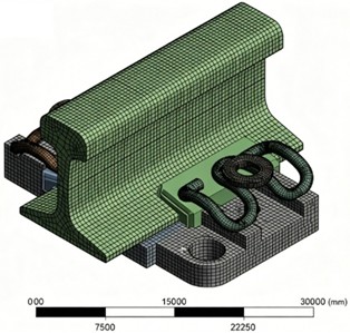
The rail connection component in this study is based on the actual engineering fastening system as the prototype, following the modeling principles of mechanical equivalence, retention of key features, and simplification of secondary details. While ensuring analysis accuracy, it balances computational efficiency and model convergence, with the three-dimensional model shown in Fig. 2. The model fully retains the core load-bearing and force-transmitting components. Among them, the steel rail is modeled with a standard I-shaped cross-section, preserving the complete geometric features of the rail head, rail web, and rail base. The spring is restored to its curved geometric shape according to actual engineering dimensions, ensuring that the mechanical behavior of elastic deformation and clamping force transmission can be accurately simulated [8]. The key contact surfaces and positioning features of constraint and force-transmitting components such as the rubber pad and gauge block are not simplified, to ensure that core constraints such as lateral limiting and vertical support are consistent with actual working conditions. Local details that do not affect the overall mechanical response are simplified. For example, non-critical fillets, chamfers, thread profiles, and other small features of the sleeper and bolts are smoothed to avoid computational non-convergence caused by local mesh distortion. Secondary structures such as embedded holes in the sleeper and small grooves on non-loaded surfaces are simplified, reducing the number of elements in the model without changing the overall stiffness and mass distribution of the components. At the same time, minor assembly gaps between components are ignored, and bonded or surface-to-surface contacts are used to simulate interactions between components, ensuring the continuity of load transfer while avoiding excessive computational time caused by too many contact pairs.
Fig. 23D model of rail connection components
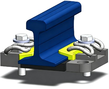
Fig. 3The result of finite element mesh division
The contact settings of the finite element model are defined based on actual assembly conditions. Considering the micro-slip effect occurring at component interfaces, the friction coefficient of all contact surfaces between various parts is set to 0.2, and penetration and intrusion between contact interfaces are strictly prohibited. The upper surface of the serpentine spring is in contact with the washer, while its lower surface is attached to the gauge block and iron base plate. The spring is fully constrained by the upper and lower contact surfaces. Therefore, the degrees of freedom of the serpentine spring are constrained in the simulation, and the damping coefficient is set to 0.02 to restore its actual mechanical state in service. A cylindrical constraint is applied to the washer with its axial degree of freedom released, allowing the washer to move axially under external loads. The assembly preload is simulated by applying a vertically downward concentrated force on the washer.
The model adopts a partitioned meshing strategy, which balances mesh accuracy and computational efficiency by combining the mechanical properties of components and analysis requirements. Solid components such as the rail and sleeper use hexahedron-dominated meshes to improve element calculation accuracy. Deformation-sensitive components such as the rubber pad and elastic clip use refined tetrahedral/mixed meshes, in which the bending regions of the spring and the contact surfaces between the rubber pad and the rail are locally refined to capture stress concentrations and deformation gradients. During the meshing process, adjusting the mesh size ensures that the quality indicators such as aspect ratio and skewness of the finite element mesh elements meet the accuracy requirements. Match the mesh of the contact pair to ensure that the nodes on the contact surface correspond, reduce contact penetration, and improve the convergence of contact analysis [9]. Through partitioned meshing, the total number of elements is effectively reduced while ensuring the accuracy of key regions, significantly improving computational efficiency. The total number of elements in the model is controlled within a reasonable range, enabling multi-condition mechanical response, modal, and fatigue analyses to be completed on a conventional workstation, while avoiding problems such as excessive computational time and convergence difficulties caused by overly dense meshes. Through continuous adjustment and optimization of the mesh, the mesh division results are shown in Fig. 3, where the number of units is 253364 and the number of nodes is 287756.
As the core load-bearing component of the track fastening system, the serpentine spring is fabricated from 68CrNiMo alloy spring steel. The mechanical properties of 68CrNiMo steel after quenching and tempering treatment are listed in Tab.1. The material exhibits uniform and stable mechanical performance, which can adapt to the stringent service environment of high-speed railway tracks involving long-term high-cycle fatigue and complex coupled stress conditions.
Table 1Material properties of serpentine springs
Parameter | Material grade | Material density | Elastic modulus | Poisson’s ratio | Yield strength | Tensile strength |
Value | 68CrNiMo | 7850 | 206 | 0.3 | 1320 | ≥ 1470 |
Unit | – | kg/m3 | GPa | – | MPa | MPa |
To simulate the mechanical response characteristics of the track in the vertical direction, the load and boundary conditions of the model are set as shown in Fig. 4. It can be seen that the fixed constraint is applied to the bottom of the sleeper, completely limiting its displacement and rotation to simulate the rigid support of the lower track bed foundation. A cylindrical constraint is applied to the outer surface of the double-headed bolt screw, limiting its radial displacement and rotation around the axis while only allowing tiny axial displacement. Meanwhile, surface-to-surface contact and bonded contact are used to simulate the interaction between various components, ensuring the continuity of load transfer and avoiding non-physical contact interference. In terms of load definition, the vertical lifting force borne on the track is set to 30 kN, and the preload forces of the bolts on both sides are 8 kN, simulating the lifting effect and non-uniform stress state of the steel rail under the action of train dynamic loads.
The displacement nephogram of the fastening system is obtained as shown in Fig. 5, which clearly reveals the deformation distribution law under the action of lifting force. It can be seen that the maximum vertical displacement of the steel rail is only 0.673 mm, and the overall deformation presents a gradient distribution from the rail head to the rail base with obvious supporting and restraining effects. The springs on both sides serve as the main deformation components, with a maximum deformation of 2.028 mm concentrated at the curved sections in contact with the gauge baffle, showing significant tensile and opening deformation. As the primary load-bearing and deformation carrier under the lifting force condition, the spring bears most of the displacement response. Meanwhile, its elastic deformation remains within the yield threshold, maintaining effective fastening pressure on the steel rail and avoiding obvious rail uplift or separation.
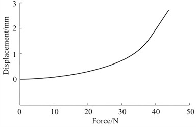
To verify the reliability and accuracy of the finite element model, static loading tests were conducted on the vertical deformation response of the rail fastening system under vertical lifting force conditions. As shown in Fig. 6(a), the test setup took the full-scale fastening system as the test object, and the actual assembly constraints were restored using fixtures on the test platform. A servo-hydraulic actuator was used to apply graded tensile forces vertically upward to the steel rail, while a high-precision displacement sensor simultaneously collected the vertical displacement data of the rail. The loading step was set as 5 kN, with loading progressing from zero to the target load incrementally. The force-displacement response curve of the rail from initial contact to the elastic deformation stage was fitted, as presented in Fig.6(b). Experimental results revealed that the deformation increased slowly with a small curve slope in the low-load range, primarily overcoming assembly gaps and initial contact stiffness. As the load increased to 20-40 kN, the curve slope increased significantly, and deformation developed rapidly with the load, indicating that the elastic clip entered the dominant elastic deformation stage. When the vertical tensile force reached 30 kN, the experimentally measured vertical deformation of the rail was 0.712 mm, which differed from the finite element simulation results by 5.5 %. This consistency verified the rationality of the simulation model in terms of boundary conditions, material parameters, and contact settings.
Fig. 4Setting of load and boundary conditions
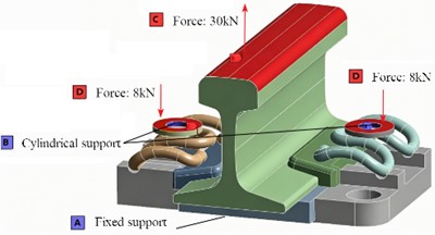
Fig. 5Calculation results of deformation
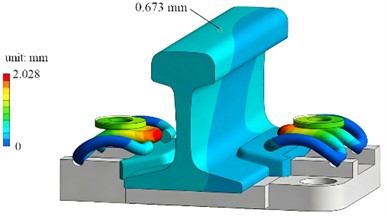
Fig. 6Experimental verification of finite element model. Photo by the author on December 17, 2025, at the Mechanics Laboratory in Qingdao
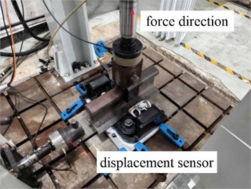
a) Experimental verification of tension response
b) The relationship curve of tension and deformation
4. Mechanical response analysis under different load conditions
4.1. Longitudinal force condition
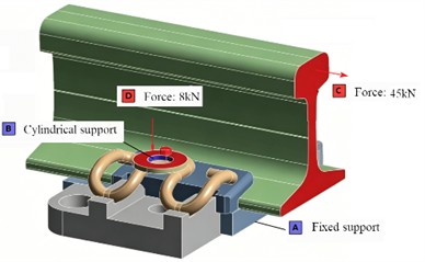
To reveal the deformation and force transmission characteristics of the fastening system under rail longitudinal loads induced by train braking, traction, and other operating conditions, and to evaluate its longitudinal restraint capability and structural reliability, simulations and analyses of the mechanical response of the rail fastening system under longitudinal force conditions were conducted. The load and boundary conditions are shown in Fig. 7(a), where a fixed support is applied to the bottom of the sleeper to completely restrict its displacement and rotation, simulating the rigid support of the lower track bed. A cylindrical support is applied to the bolt shank to limit radial displacement and rotation around the axis, while only allowing tiny axial displacement to restore the assembly state. In terms of loading, a horizontal force of 45 kN is applied along the longitudinal direction of the rail to simulate the longitudinal load transmitted by the train, and an 8 kN preload is applied to the bolt to restore the clamping constraint of the spring on the rail.
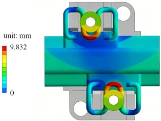
The deformation nephogram under the longitudinal force condition is shown in Fig. 7(b). It can be seen that the rail produces directional displacement along the longitudinal direction, with deformation attenuating gradually from the loaded side of the rail head to the rail base. As the main deformation component, the spring reaches a maximum deformation of 9.832 mm, which is concentrated in the curved sections in contact with the bolt and gauge baffle, showing obvious tensile opening and shear deformation characteristics. The deformation distribution presents an asymmetric feature: the deformation of the spring on the loaded side is significantly larger than that on the unloaded side, indicating that when the longitudinal load is transmitted from the rail to the spring, the spring on one side bears the main anti-slip restraint function. Its elastic deformation not only absorbs the energy of the longitudinal load but also maintains the clamping state on the rail. Meanwhile, the deformations of the sleeper and the pad are extremely small, indicating that the fixed support effectively blocks the downward transmission of the load, and the system deformation is mainly dominated by the elastic deformation of the spring. This result verifies the longitudinal restraint mechanism of the fastening system.
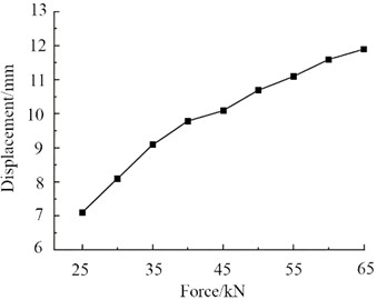
The maximum deformation response law of the fastening system under different longitudinal force conditions is shown in Fig. 7(c). It can be seen that as the longitudinal force increases from 25 kN to 65 kN, the maximum deformation of the spring shows an approximately linear growth trend, rising steadily from about 7.0 mm to about 11.9 mm, with a significant positive correlation between the deformation increment and the load increment. The overall slope of the curve is stable without obvious abrupt changes or nonlinear inflection points, indicating that the spring remains in the elastic deformation stage within this load range, without yielding or contact failure, and the coupling relationship between deformation response and longitudinal force is stable. Meanwhile, the growth rate of deformation slows down slightly with increasing load, reflecting the stiffness strengthening effect of the spring under large loads, which is closely related to the geometric nonlinear contact characteristics of the elastic clip and also verifies its deformation bearing capacity under the longitudinal load of the train.
The stress distribution law of the spring under the longitudinal force condition is shown in Fig. 7(d). It can be seen that the maximum equivalent stress reaches 1016.431 MPa, which is concentrated in the curved section of the elastic clip and the contact area with the bolt, forming an obvious high-stress zone, while the stress level in the straight section of the elastic clip is relatively low. The stress distribution presents an asymmetric feature: the stress level of the elastic clip on the loaded side is significantly higher than that on the unloaded side, which echoes the deformation-dominated characteristic of the loaded side in the deformation nephogram, indicating that after the longitudinal load is transmitted through the rail, the anti-slip restraint function is mainly borne by the single-side elastic clip, resulting in local stress concentration.
4.2. Rolling force condition
To obtain the mechanical response of the rail fastening system under conditions such as train curve negotiation and track irregularities, the analysis condition is set as the lateral force load induced by train roll, as shown in Fig. 8(a). Regarding boundary conditions, a fixed support is applied to the bottom of the sleeper to completely restrict its displacement and rotation, simulating the rigid support of the lower track bed. A cylindrical support is applied to the bolt shank to limit radial displacement and rotation about the axis, while only allowing minor axial displacement to restore the actual assembly state of the bolt. In terms of load settings, an 8 kN preload is applied to the bolts on both sides to simulate the initial clamping force of the spring on the rail. Meanwhile, a 30 kN rolling force is applied transversely to the rail to simulate the lateral load caused by train roll, fully reproducing the actual stress state of the fastening system.
Fig. 7Mechanical response analysis under longitudinal force condition
a) Setting of load and boundary conditions
b) Calculation results of deformation
c) Maximum deformation under different longitudinal force conditions
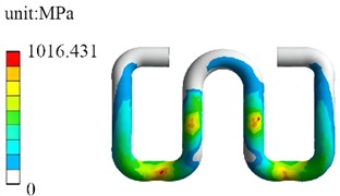
d) Stress distribution of spring
The deformation nephogram under the rolling force condition is shown in Fig. 8(b), which intuitively presents the displacement distribution characteristics of the fastening system. It can be seen that the rail produces a directional lateral displacement toward the load application side, with deformation gradually attenuating from the loaded side of the rail head to the unloaded side. The springs on both sides are the main deformation components, among which the deformation of the spring on the loaded side is significant, with a maximum deformation of 10.583 mm concentrated in the curved sections in contact with the bolt and gauge baffle, showing obvious tensile opening and shear deformation characteristics, while the deformation of the spring on the unloaded side is relatively small. This asymmetric deformation distribution reflects that under the action of the rolling force, the spring on the loaded side bears the main lateral restraint and anti-overturning effect, serving as the main deformation carrier of the system.
The maximum deformations under different rolling force conditions are shown in Fig. 8(c). This curve shows the variation law of the maximum deformations of the left and right springs under different rolling forces. It can be seen that as the rolling force increases from 30 kN to 55 kN, the maximum deformations of the springs on both sides show an approximately linear growth trend. The deformation of the right loaded-side spring increases from about 10.1 mm to about 11.6 mm, and the deformation of the left unloaded-side spring increases from about 9.0 mm to about 10.4 mm. The deformation on the loaded side is always greater than that on the unloaded side, and the difference between the two gradually expands with the increase of the load. The slope of the curve is stable without obvious abrupt changes or nonlinear inflection points, indicating that within this load range, the spring remains in the elastic deformation stage without yielding or contact failure, verifying its stable deformation bearing capacity under the rolling force.
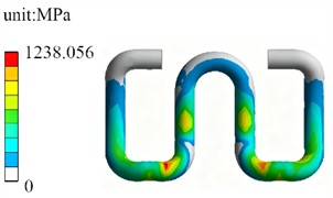
The stress nephogram of the spring under the rolling force condition is shown in Fig. 8(d). The maximum equivalent stress reaches 1238.056 MPa, which is concentrated in the curved sections of the spring in contact with the bolt and rail, forming obvious high-stress zones, while the stress level in the straight sections of the spring is relatively low. The stress distribution presents an asymmetric feature, with the stress level of the spring on the loaded side significantly higher than that on the unloaded side, which echoes the deformation distribution law, indicating that after the rolling force is transmitted through the rail, the lateral restraint function is mainly borne by the spring on the loaded side, resulting in local stress concentration. The high-stress zones completely coincide with the main deformation regions of the spring, indicating that the curved sections are the weak links of the spring under the rolling force condition and potential risk points for fatigue failure, providing a key basis for subsequent fatigue life assessment and structural optimization.
Fig. 8Mechanical response analysis under rolling force condition
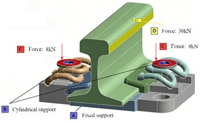
a) Setting of load and boundary conditions
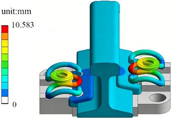
b) Calculation results of deformation
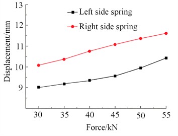
c) Maximum deformation under different rolling force
d) Stress distribution of spring
5. Modal and fatigue life characteristics analysis of serpentine spring
5.1. Modal characteristics analysis
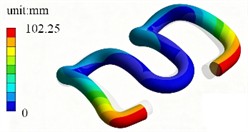
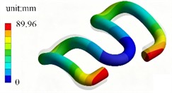
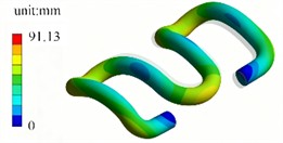
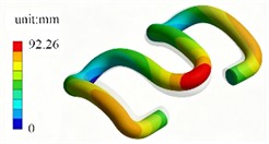
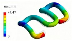
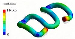
Through finite element modal simulation, the first six mode shapes and natural frequencies are obtained as shown in Fig. 9. It can be seen that the first six natural frequencies of the serpentine spring are concentrated in the range of 500-750 Hz, and the mode shapes are dominated by coupled bending and torsional deformation, with the deformation characteristics of each mode showing a clear progressive pattern. The first mode (506.14 Hz) is a basic symmetric bending mode, with deformation concentrated at both ends of the spring in the form of overall swinging, and the maximum deformation reaches 102.25 mm. In the second mode (558.37 Hz), the bending nodes move toward the middle, with the two ends swinging in opposite directions, enhancing the local bending effect. The third (618.87 Hz) and fourth (664.08 Hz) modes gradually exhibit bending-torsion coupling characteristics, with torsional deformation beginning to appear in the middle section of the spring and the deformation distribution expanding from both ends to the center. The fifth mode (703.35 Hz) presents a multi-node bending mode, with deformation becoming more dispersed. The sixth mode (744.81 Hz) is a strongly coupled mode with significant superposition of bending and torsion, where the deformation amplitude of local sections reaches the maximum among the six modes (116.65 mm), reflecting the complexity of the spring's stiffness distribution under high-order modes. Overall, as the mode order increases, the natural frequency rises monotonically, the mode shapes evolve from simple bending to multi-node and multi-coupled deformation, and the deformation distribution becomes more complex, demonstrating the order-wise evolution law of the dynamic characteristics of the serpentine spring structure.
Fig. 9The first six modal shapes
a) First order (506.14 Hz)
b) Second order (558.37 Hz)
c) Third order (618.87 Hz)
d) Fourth order (664.08 Hz)
e) Fifth order (703.35 Hz)
f) Sixth order (744.81 Hz)
Combining the excitation characteristics of train operation with the modal frequencies of the spring, the resonance probability can be analyzed from two aspects: excitation matching and modal suppression effects [10, 11]. On the one hand, the main excitation sources during train operation include track irregularities, wheel-rail impacts, and component vibration transmission. At operating speeds of 100-350 km/h, the dominant frequency of track irregularity excitation is usually below 300 Hz, which is much lower than the first natural frequency of the spring, resulting in an extremely low probability of direct resonance. At 350 km/h, high-frequency excitations such as wheel-rail scratches and joint impacts may partially overlap with the first six natural frequencies of the spring, theoretically posing a resonance risk under impact excitation. However, such impacts are random broadband excitations, making it difficult to maintain an exact match with a single modal frequency for a long time, and the energy attenuates significantly during transmission, leading to limited actual coupling effects [12, 13]. On the other hand, the modal characteristics of the spring have a natural suppressing effect on resonance. The first six mode shapes are all local bending or torsional deformations, with vibration energy concentrated in local sections rather than large overall swings, resulting in a weak energy amplification effect during resonance. In summary, under normal train operating conditions, the probability of destructive resonance occurring in the serpentine spring is extremely low.
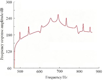
The test scheme for the natural frequency of the serpentine spring is shown in Fig. 10. Based on the modal test setup using the electronic hammer excitation method, a pulse excitation is applied to the fastening system by an excitation hammer, while acceleration sensors collect the dynamic response signals of the structure to obtain frequency response data. Fig. 11 presents the frequency response curve under hammer excitation, where the peak positions correspond to the natural frequencies of the structure. The first six natural frequencies measured experimentally are in good agreement with the results of the finite element modal simulation, and the deviations between the measured and simulated values of each natural frequency are all within the allowable engineering range, with a maximum deviation of only 3.2 %.
5.2. Fatigue life characteristics analysis
During the operation of trains, the serpentine springs of track fastening systems are continuously subjected to alternating displacement loads induced by wheel-rail coupling interactions, which easily leads to fatigue cracking and fracture failures. To accurately evaluate the fatigue life of springs under various load conditions and reveal the underlying fatigue failure mechanisms, finite element fatigue simulations are conducted based on the high-cycle fatigue theory, and indoor fatigue tests are performed correspondingly to verify the accuracy of the numerical model. The numerical simulation adopts the S-N fatigue curve and Miner linear cumulative damage criterion as the core theoretical basis, combined with the composite stress fatigue and stress concentration theories to carry out mechanical mechanism analysis. The S-N curve characterizes the quantitative relationship between stress amplitude and fatigue failure cycles of metallic materials under alternating loads, serving as the fundamental principle for fatigue life calculation of structural components. When the cyclic stress exceeds the fatigue limit of the material, the fatigue cycle number decreases exponentially with the increase of stress amplitude. The bending sections of serpentine springs bear coupled bending and shear stresses under service loads, presenting a typical alternating composite stress state. In the simulation calculation, an equivalent conversion method is adopted to convert the composite stress into equivalent stress amplitude, which is substituted into the S-N curve to solve the fatigue life under single-level load conditions. According to the Miner linear cumulative damage theory, the total fatigue damage of a component under alternating loads is the linear superposition of damage caused by each level of load. Fatigue fracture of the component is judged to occur when the cumulative damage value reaches 1.
Fig. 10Test of natural frequency. Photo by the author on March 10, 2026, at the Mechanics Laboratory in Qingdao
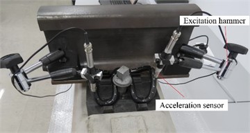
Fig. 11Response results of hammer excitation
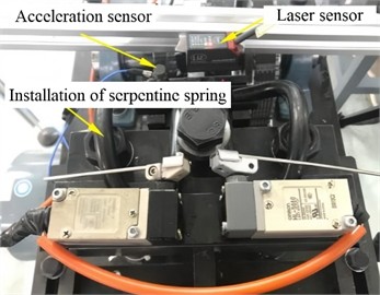
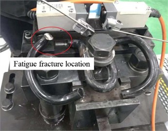
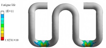
Four displacement amplitude working conditions are set for the fatigue simulation, including 1.0 mm, 1.4 mm, 1.7 mm, and 2.0 mm. The indoor fatigue test adopts a fixed displacement load of 1.4 mm, which can effectively validate the simulation results. The loading frequency is consistent with the operating frequency of the test system to reproduce the alternating deformation characteristics of serpentine springs in actual train operation. On this basis, the influence law of different load amplitudes on the fatigue performance of serpentine springs is systematically explored. To investigate the fatigue life characteristics of the serpentine spring efficiently, the fatigue test platform was built, as shown in Fig. 12(a). The test bench realizes closed-loop monitoring of vibration displacement and dynamic response through acceleration sensors and laser displacement sensors, which can accurately reproduce the alternating load conditions borne by the serpentine spring during train operation. Fig. 12(b) shows the fatigue fracture state of the spring after the test. The fracture location is located on the inner side of the curved section of the spring, which completely coincides with the high-stress concentration area predicted by the simulation. This indicates that this position, subjected to long-term alternating bending and shear coupling stresses, has become a weak link for fatigue failure. The fatigue life nephogram shown in Fig. 12(c) reveals that the life distribution of the serpentine spring exhibits significant regional differences. The low-life regions are concentrated on the inner side of the curved section corresponding to the experimental fracture location, with a minimum life of approximately 1.923×10¹⁰ cycles, directly reflecting the influence of stress concentration on fatigue performance. The comparison curve shown in Fig. 12(d) indicates that as the vibration displacement load increases from 1.0 mm to 2.0 mm, the fatigue life of the spring shows a logarithmic linear decay trend. Meanwhile, the test result under the 1.4 mm displacement load is in good agreement with the simulation curve, verifying the accuracy of the fatigue simulation model in predicting the load-life relationship. This also demonstrates that the model can be effectively used for fatigue life assessment of serpentine springs under different load conditions.
Fig. 12Simulation and experimental results of fatigue life analysis. Photo by the author on March 6, 2026, at the Mechanics Laboratory in Qingdao
a) Fatigue testing platform
b) Fatigue fracture state
c) Fatigue life simulation results
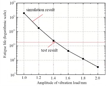
d) Comparison between simulation results and test results
6. The influence of structural parameters on vibration response characteristics
6.1. Effects on shock response
To carry out the impact load response analysis and modal analysis of serpentine springs with different cross-sectional dimensions, a parametric design method was adopted in this study, and four comparison schemes (DR_1 to DR_4) were designed with the outer radius and inner hole radius of the spring wire as control variables, as shown in Fig. 13 and Table 2. Among them, the outer radius was kept constant for DR_1 and DR_2, and the wall thickness was varied by adjusting the inner hole radius. For DR_3 and DR_4, the outer radius was also kept unchanged, and different wall thickness gradients were formed by setting different inner hole radii. Meanwhile, a comparison of the overall cross-sectional dimensions was realized between DR_2 and DR_3 through the same inner hole radius but different outer radii. This control variate-based parameter selection method can effectively separate the influences of cross-sectional dimension and wall thickness on structural performance, providing a reliable basis for variable control.
In terms of impact load response, different cross-sectional moments of inertia will directly affect the bending stiffness and stress distribution of the spring, and the gradient of cross-sectional dimensions from DR_1 to DR_4 can clearly demonstrate the influence law of stiffness variation on the impact response. In terms of modal analysis, changes in cross-sectional dimension and wall thickness will alter both the mass distribution and stiffness matrix of the structure simultaneously, and the influence weights of cross-sectional parameters on natural frequencies can be quantitatively identified through the comparison of the four schemes.
Fig. 13Sectional structural parameters
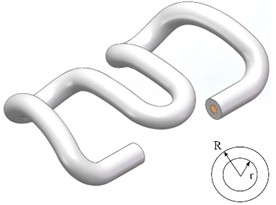
Table 2Dimensions of different spring cross-sections
Structural parameters | DR_1 | DR_2 | DR_3 | DR_4 |
/ mm | 6 | 6 | 7 | 7 |
/ mm | 2 | 3 | 3 | 3.5 |
The acceleration response test of the serpentine spring under impact load is intended to reproduce the vertical impact conditions transmitted by the wheel-rail system during train operation, collect the dynamic acceleration signals of the spring, and verify its dynamic performance and resonance risk under service conditions [14]. Meanwhile, a unified test benchmark is provided for comparative schemes with different cross-sectional dimensions, the influence law of structural parameters on dynamic response is quantitatively analyzed, and key experimental evidence is offered for structural optimization, impact resistance improvement, and fatigue life evaluation of the spring.
The serpentine spring serves as the key force-transmitting and elastic vibration-damping component of high-speed railway fastening systems. During train operation, the wheel-rail interaction generates dynamic impact loads characterized by high frequency, transience and large amplitude. Such loads are a major factor leading to stress concentration, local deformation and even fatigue cracking of the spring. Analyzing the time-varying characteristics of acceleration in the impact response of the serpentine spring can fully reflect the transient dynamic behavior of the structure under wheel-rail impact in high-speed operation, and quantitatively evaluate its vibration reduction, energy dissipation and dynamic load-bearing performance. The relevant results can provide theoretical and experimental support for the structural optimization, performance improvement and engineering application of track serpentine springs. In accordance with the test specifications, the impact test conditions are summarized in Table 3. By means of this loading method, the amplitude and loading rate of the impact load can be controlled, thereby providing a unified and controllable load boundary condition for the comparative testing of springs with different cross-sectional dimensions and ensuring variable consistency in subsequent performance analysis.
Table 3Dimensions of different spring cross-sections
Impact load | Impact velocity | Impact mass | Load duration | Load rise time |
90 kN | 1.2 m/s | 750 kg | 50 ms | 10 ms |
The application method of the impact load is shown in Fig. 14(a). A vertically loaded servo-driven system is adopted, through which dynamic impact loads are applied along the main stress axis of the spring. This allows the vertical impact conditions transmitted by wheel-rail excitation to the serpentine spring during train operation to be accurately reproduced. The sensor installation scheme is presented in Fig. 14(b).
Fig. 14Test of spring acceleration response under impact load. Photo by the author on March 9, 2026, at the Mechanics Laboratory in Qingdao
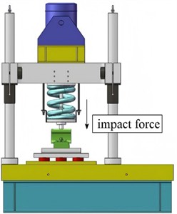
a) Direction of impact load
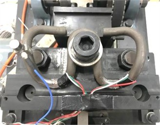
b) Installation of sensors
Acceleration sensors and strain gauges are arranged in critical stress-concentrated regions such as the inner side of the curved section of the spring, enabling the synchronous acquisition of dynamic acceleration and stress responses during the impact process. The proposed loading and sensing scheme is directly oriented to the actual stress state of the spring in service. It not only allows the dynamic response characteristics under impact load to be effectively captured but also provides reliable experimental data support for subsequent analysis of the influence of cross-sectional parameters on the impact resistance of the spring, ensuring the scientificity and pertinence of the test scheme.
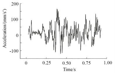
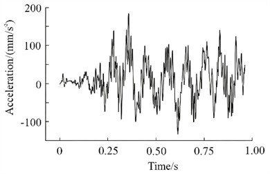
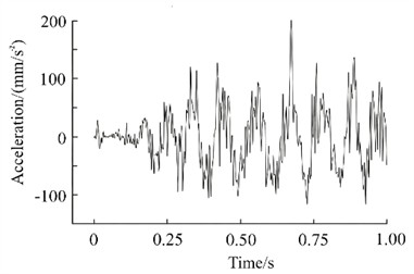
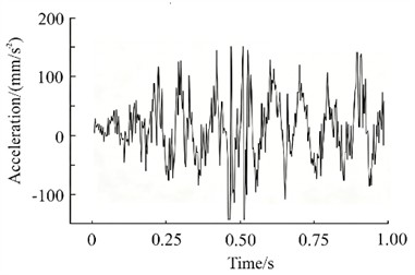
The acceleration response results of springs under different structural conditions are presented in Fig. 15. From the perspective of response characteristics, significant differences in acceleration amplitudes are observed among the four springs, which are directly related to their cross-sectional parameters. The lowest acceleration peak and the most gentle overall fluctuation are exhibited by DR_1, demonstrating the optimal dynamic stability. For DR_2, a slight increase in vibration amplitude is caused by the reduced wall thickness and decreased section stiffness. The acceleration responses of DR_3 and DR_4 are significantly amplified, with the highest peak observed in DR_3. This is mainly attributed to the imbalance between stiffness and mass after the increase in cross-sectional dimensions, leading the natural frequency of the structure to approach the impact excitation frequency band and triggering an obvious vibration amplification effect. Through comprehensive comparison, it is found that the dynamic response performance of the spring does not increase linearly with the increase in cross-sectional dimensions, but is determined by the synergistic matching of stiffness and mass. The optimal balance between stiffness and mass is achieved by DR_1 with moderate wall thickness and reasonable section moment of inertia, resulting in the best attenuation effect on impact loads. In contrast, for DR_3 and DR_4 with simply increased outer radius, the shift in natural frequency caused by increased mass aggravates the vibration response instead. It is indicated that wall thickness optimization is more effective in improving impact resistance than blindly increasing cross-sectional dimensions, and special attention should be paid to avoiding the natural frequency falling into the sensitive frequency band of wheel-rail impact excitation in the design.
Fig. 15Acceleration response results of springs under different structural conditions
a) DR_1
b) DR_2
c) DR_3
d) DR_4
6.2. Effects on natural frequency and stiffness
Investigating the influence mechanism of cross-sectional geometric parameters on the modal characteristics of serpentine springs can not only distinguish differences in frequency response, but also screen out optimized schemes that can avoid the dominant wheel-rail excitation band and improve the dynamic stability of the structure. Analyzing the evolution characteristics of spring stiffness under cyclic loading enables us to clarify the high-cycle fatigue mechanical behavior of components with different cross-sections. It also reveals the influence laws of cross-sectional dimensions on work hardening, residual stress accumulation and abnormal stiffness variation, and evaluates the mechanical reliability of each scheme during long-term service.
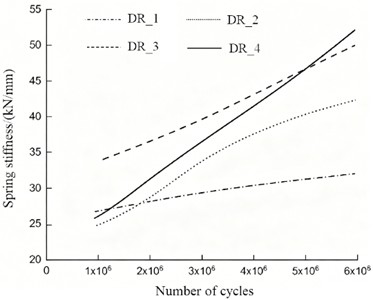
The variations in natural frequencies of serpentine springs with different cross-sectional dimensions as a function of modal order are presented in Fig. 16. The change law of spring stiffness with the number of loading cycles is illustrated in Fig. 17. Together, these two figures reveal the regulatory mechanisms of cross-sectional parameters on both dynamic and fatigue performances. In terms of natural frequency characteristics, the natural frequencies of the four cross-sectional schemes (DR_1 to DR_4) all exhibit a linear increasing trend with the rise in modal order, yet significant differences are observed among different schemes. The natural frequencies of DR_3 and DR_4 are generally higher than those of DR_1 and DR_2, with DR_2 showing the lowest frequencies. This discrepancy is attributed to the synergistic effect of cross-sectional moment of inertia and mass. The increase in stiffness caused by the enlargement of the outer radius exceeds the influence of mass growth, leading to a significant upward shift in the natural frequencies of DR_3 and DR_4. In contrast, DR_2, due to its larger inner radius and the lowest cross-sectional stiffness, exhibits natural frequencies at the lower limit among the four schemes. From the perspective of engineering applications, the frequency curve of DR_1 lies at an intermediate level, demonstrating superior dynamic stability [15, 16].
Regarding the evolution of stiffness, the spring stiffness of all four schemes shows an upward trend with the increase in the number of cyclic loading cycles, but distinct differences exist in the growth rates. The stiffness increments of DR_3 and DR_4 are notably higher than those of DR_1 and DR_2. Among them, the stiffness of DR_3 increases most drastically, with a growth of over 100 % compared to the initial value after 6×10⁶ cycles. In contrast, the stiffness growth of DR_1 is the most moderate, increasing by only approximately 20 %. Owing to their larger wall thicknesses, DR_3 and DR_4 are prone to work hardening and residual stress accumulation under cyclic loading, resulting in a rapid rise in stiffness. On the other hand, the cross-sectional stress distribution of DR_1 is more uniform, leading to a more stable stiffness evolution during the fatigue process.
A comprehensive evaluation of both dynamic and fatigue performances reveals that the DR_1 scheme exhibits the optimal overall performance in terms of natural frequency distribution and stiffness stability. This indicates that the optimization of cross-sectional dimensions requires simultaneous consideration of stiffness-mass matching and mechanical stability during fatigue. Simply increasing the cross-sectional dimension (e.g., DR_3) can improve the initial stiffness but exacerbates stiffness degradation and resonance risks during fatigue, which is instead detrimental to long-term service performance.
Fig. 16The variations in natural frequencies of serpentine springs
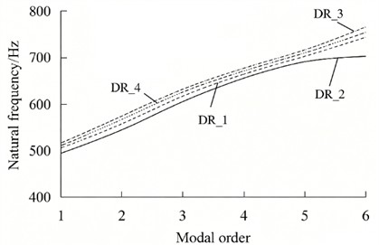
Fig. 17The change law of spring stiffness with the number of loading cycles
Conventional elastic clips, such as Type WJ-7 and SKL series, generally have low-order natural frequencies below 500 Hz, particularly the first-order bending mode that is highly susceptible to resonance. This frequency band overlaps substantially with the dominant wheel-rail excitation range, where vibrations are generated by short-pitch rail corrugation, wheel polygonal wear and track irregularities. When the first-order mode (100-300 Hz) is directly coupled with the excitation frequency of short-pitch rail corrugation, modal resonance takes place, which drastically amplifies the dynamic stress amplitude at critical areas including the clip root. The elevated dynamic stress initiates microcracks in stress concentration zones, and these cracks gradually propagate to form macro fractures. The four innovative DR-series elastic clips proposed in this research adopt cross-sectional configuration optimization (e.g., DR-type hollow structure) and stiffness distribution adjustment. As a result, their first six natural frequencies are entirely shifted to 500-750 Hz. All of their first-order natural frequencies exceed 500 Hz, so the structures stay completely outside the dominant energy band of wheel-rail vibration. The excitation energy above 500 Hz is less than 10 % of that in the dominant band. Even if minor frequency coupling occurs, the dynamic stress amplitude remains far lower than that of conventional structures.
7. Conclusions
This study took high-speed railway rail connection components as the research objects. By means of finite element simulation, experimental verification and parametric analysis, the dynamic mechanical responses of components, the modal and fatigue properties of serpentine springs, as well as the influences of cross-sectional parameters were systematically investigated. The main conclusions were drawn as follows:
1) The established finite element model of rail connection components was proved to possess high reliability. Verified by static loading tests, reasonable arrangements of boundary conditions, material parameters and contact behaviours were adopted in the model, and the deviation of rail deformation between simulation and test results was only 5.5 %. Under longitudinal loads, asymmetric deformation distributions were exhibited by the springs, and the springs on the loaded sides were responsible for the major anti-slip restraint, with a maximum equivalent stress of 1016.431 MPa. Under rolling loads, the lateral constraint and anti-overturning effects were undertaken by the loaded-side springs, and the maximum equivalent stress reached 1238.056 MPa. The curved segments of springs were identified as the critical stress concentration areas and potential weak positions for fatigue failure.
2) The first six order natural frequencies of serpentine springs were concentrated within the range of 500-750 Hz. Corresponding mode shapes were gradually transformed from simple symmetric bending deformation to multi-node bending-torsion coupled deformation. Under normal operating conditions, a low matching degree was presented between spring natural frequencies and wheel-rail excitation frequencies, leading to an extremely low risk of destructive resonance. The fatigue life was decreased logarithmically and linearly with the increase of vibration displacement. Satisfactory consistency was observed between experimental data and simulation curves under the displacement load of 1.4 mm, which indicated that the fatigue simulation model could be reliably applied to the fatigue life evaluation of serpentine springs.
3) Significant regulatory effects of cross-sectional parameters on the dynamic and fatigue performances of serpentine springs were confirmed. Among the four structural schemes, the DR_1 spring achieved the optimal matching of stiffness and mass, and the most stable impact response together with the mild stiffness evolution were obtained. Although the initial stiffness was improved by simply increasing the outer radius (DR_3 and DR_4), the offset of natural frequency, amplified vibration and rapid stiffness degradation were induced accordingly. The stiffness growth rate of DR_3 exceeded 100 %, which seriously weakened the long-term service performance. Compared with the blind enlargement of overall dimensions, wall thickness optimization was proven to be more effective in enhancing the impact resistance of springs. The natural frequencies should be prevented from falling into the sensitive frequency bands of wheel-rail impact excitation in structural design.
References
-
J. Konecny, S. Ozana, J. Choutka, and M. Prauzek, “Towards railways safety: a systematic review on predictive diagnostics for axle bearings,” Measurement, Vol. 257, p. 118510, Aug. 2025, https://doi.org/10.1016/j.measurement.2025.118510
-
R. K. Bhamu, A. Shukla, S. C. Sharma, and S. P. Harsha, “Vibration response of steam turbine healthy and cracked blade under the stress stiffening and spin softening effects,” Proceedings of the Institution of Mechanical Engineers, Part K: Journal of Multi-body Dynamics, Vol. 236, No. 2, pp. 224–243, Feb. 2022, https://doi.org/10.1177/14644193221078656
-
A. Daşdemir, “A modal analysis of forced vibration of a piezoelectric plate with initial stress by the finite-element simulation,” Mechanics of Composite Materials, Vol. 58, No. 1, pp. 69–80, Mar. 2022, https://doi.org/10.1007/s11029-022-10012-7
-
D. Ren, G. Tao, W. Li, and Z. Wen, “Short-pitch corrugation formation on resilient fastener metro tracks explained using rail-bending vibrations within the bogie wheelbase,” Proceedings of the Institution of Mechanical Engineers, Part F: Journal of Rail and Rapid Transit, Vol. 238, No. 4, pp. 449–460, Jun. 2023, https://doi.org/10.1177/09544097231182748
-
C. V. Bhore et al., “Assessment of metro-induced vibrations on photo-voltaic modules for their solar energy degradation potential,” Solar Energy, Vol. 255, pp. 257–273, Mar. 2023, https://doi.org/10.1016/j.solener.2023.03.025
-
A. V. Plekhanov and S. Y. Ryzhov, “Features of the numerical implementation of the analytical solution of the rail vibration equation on a viscoelastic foundation in an electromagnetic accelerator,” Mathematical Models and Computer Simulations, Vol. 17, No. 5, pp. 624–634, Oct. 2025, https://doi.org/10.1134/s207004822570036x
-
C. Knuth, G. Squicciarini, and D. Thompson, “An efficient model for predicting the sound radiation from a railway rail accounting for cross-section deformation,” Journal of Sound and Vibration, Vol. 618, p. 119323, Jul. 2025, https://doi.org/10.1016/j.jsv.2025.119323
-
Y. Pi, J. Zhang, X. Tang, and J. Zhu, “Three-dimensional dynamic modeling and simulation of a multi-cable winding hoister system considering bidirectional coupling between cage and flexible guides,” Journal of Vibration and Control, Vol. 29, No. 7-8, pp. 1678–1699, Mar. 2022, https://doi.org/10.1177/10775463211068901
-
J. R. Cho, “Anisotropic large deformation and fatigue damage of rubber-fabric braid layered composite hose,” Procedia Engineering, Vol. 173, pp. 1169–1176, Feb. 2017, https://doi.org/10.1016/j.proeng.2016.12.097
-
H. D. Chalak, A. M. Zenkour, and A. Garg, “Free vibration and modal stress analysis of FG-CNTRC beams under hygrothermal conditions using zigzag theory,” Mechanics Based Design of Structures and Machines, Vol. 51, No. 8, pp. 4709–4730, Aug. 2023, https://doi.org/10.1080/15397734.2021.1977659
-
R. Xue, Z. Ren, T. Fan, and S. Rakheja, “Vertical vibration analysis of a coupled vehicle-container model of a high-speed freight EMU,” Vehicle System Dynamics, Vol. 60, No. 4, pp. 1228–1252, Oct. 2022, https://doi.org/10.1080/00423114.2020.1850810
-
B. K. Meisuh, J. Huh, A. Haldar, and I.-T. Kim, “Comparison of seismic responses of a jumbo-size container crane retrofitted with braces, dampers, and isolation systems,” Ocean Engineering, Vol. 262, p. 112222, Sep. 2022, https://doi.org/10.1016/j.oceaneng.2022.112222
-
L. Quynh, Z. Jianrun, N. Liem, B. Cuong, L. X. Long, and D. T. Phuong, “Experimental modal analysis and optimal design of cab’s isolation system for a single drum vibratory roller,” Vibroengineering Procedia, Vol. 31, pp. 52–56, May 2020, https://doi.org/10.21595/vp.2020.21325
-
J. Wang, C. Xu, Y. Xu, X. Qi, Z. Liu, and H. Tang, “Vibration analysis and parameter optimization of the longitudinal axial flow threshing cylinder,” Symmetry, Vol. 13, No. 4, p. 571, Mar. 2021, https://doi.org/10.3390/sym13040571
-
D. Perfetto, C. Pezzella, V. Fierro, N. Rezazadeh, A. Polverino, and G. Lamanna, “FE modelling techniques for the simulation of guided waves in plates with variable thickness,” Procedia Structural Integrity, Vol. 52, No. 1, pp. 418–423, Feb. 2024, https://doi.org/10.1016/j.prostr.2023.12.042
-
R. Talebitooti, M. Zarastvand, and H. Darvishgohari, “Multi-objective optimization approach on diffuse sound transmission through poroelastic composite sandwich structure,” Journal of Sandwich Structures and Materials, Vol. 23, No. 4, pp. 1221–1252, 2019, https://doi.org/10.1177/1099636219854748
About this article

The paper is supported by the scientific research projects (KYH2024177).
The datasets generated during and/or analyzed during the current study are available from the corresponding author on reasonable request.
The authors declare that they have no conflict of interest.

