Abstract
To solve the engineering problems of severe vibration in the dehydration stage, insufficient reliability of load-bearing components, and the difficulty in balancing lightweight design and dynamic performance of industrial washing machines, mechanical performance analysis of key load-bearing components and optimization of vibration isolation systems were conducted. Dynamic modeling, finite element simulation and multi-objective optimization methods were integrated under extreme working load conditions. The dynamic model of the vibration isolation system was established by the Lagrange method. The rigid-flexible coupling simulation model of the cabinet and the refined finite element model of the inner cylinder were constructed. The Kriging surrogate model was adopted to fit nonlinear correlations between structural design variables and mechanical responses. Optimization results quantitatively demonstrate that the cabinet achieves an 11.0 % weight reduction and the inner cylinder realizes a 9.8 % mass cut without exceeding the original maximum stress and fundamental frequency constraints. After optimizing the matching of suspension spring stiffness and damping coefficient, the resonance peak amplitude of the inner cylinder center of mass vibration decreased by 58 %, effectively suppressing the equipment resonance amplification phenomenon and improving the dehydration stability and efficiency. This study provides a complete simulation-surrogate multi-objective optimization workflow for heavy laundry equipment bearing structures and vibration isolation systems under extreme service loads.
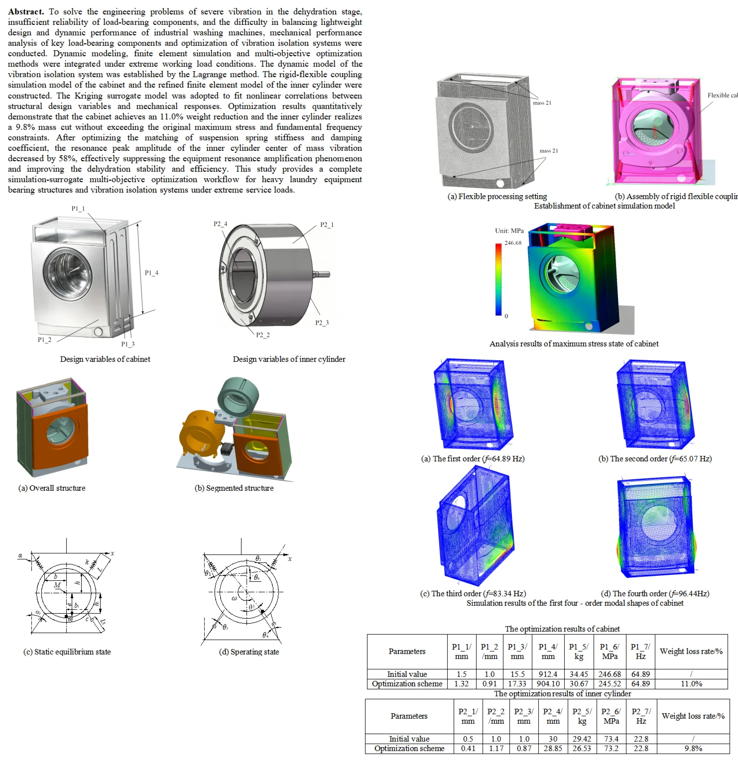
Highlights
- A multi-objective optimization system for industrial washing machines under extreme load conditions was constructed.
- A structural optimization method based on the response surface surrogate model was proposed, which solves the problems of high computational cost and low iteration efficiency of single finite element analysis in the optimization process.
- With the constraint of not increasing the peak load response, the spring stiffness and damping coefficient of the vibration isolation system were optimized.
1. Introduction
Industrial washing machines are usually required to operate for a long time under extreme load conditions, such as high-speed rotation with high-density materials. Such extreme working conditions put forward stringent requirements on the structural and dynamic performance of the equipment [1, 2]. Nevertheless, there still exist many challenges in the design and optimization of industrial washing machines. As the core load-bearing components, the cabinet and cylinder assemblies are prone to low natural frequency, local stress concentration and structural mass redundancy under extreme loads, which also raise material consumption and manufacturing costs. An unreasonably designed vibration isolation system will not only impair the structural stability of equipment operation, but also easily trigger resonance and bring potential fatigue damage risks [3]. Against this background, it is of important engineering practical necessity to carry out multi-objective optimization research on industrial washing machines under extreme load conditions and solve the problem of collaborative optimization between structural and dynamic performance.
Representative studies on the structural optimization of industrial washing machines include: Jiao [4] used ADAMS to construct a virtual prototype model of a washing machine and studied the effects of spring tilt angle, spring stiffness coefficient, damper damping coefficient, and eccentric clothing mass on the horizontal amplitude of the washing machine. In addition, single factor optimization experiments were conducted to investigate the influence of design variables on system amplitude, and the optimal combination of influencing factors was solved through multi factor optimization experiments. Choi [5] proposed adopting Bayesian optimization to predict the unbalance characteristics during the dehydration process and derived the optimal control specifications for its minimization. This research method can construct a prediction model based on collected data. Meanwhile, the acquisition function is utilized for efficient solution exploration to obtain the optimal solution. Hashemian [6] developed a Bayesian optimization framework. The objective function was set to minimize the maximum displacement amplitude of the inner drum of the washing machine. By adopting the Gaussian process model, genetic algorithm (GA) and carefully selected acquisition functions, adaptive sampling and optimal design parameter searching can be realized. Flores [7] adopted a simple genetic algorithm to determine the optimal damping, stiffness and position parameters of suspension components by minimizing the weighted fitness function. The fitness function employed a bounding box to enclose the kinematic data of the washing machine’s center of mass and achieve its minimization. Su [8] established an integrated model of RecurDyn and Particle Works to analyze the dynamic behavior of washing machines. By using modal coordinates on a flexible multibody model, it is pointed out that the vibration of a top mounted washing machine is caused by the deformation of the drum due to unbalanced mass.
As thin-walled load-bearing components, the cabinet and inner drum of industrial washing machines are provided with structural mass redundancy. Nevertheless, severe local stress and excessive vibration amplitudes can be easily induced under eccentric overloads if unreasonable structural designs are adopted. Conventional lightweight structural design and vibration isolation performance optimization are generally carried out independently, and balanced synergistic lightweight effects cannot be achieved via a single vibration reduction scheme as a result. In terms of structural optimization, low iteration efficiencies are exhibited by existing single-objective optimization and single-factor tests. Accurate fitting of the nonlinear coupling relationships between structural geometric parameters and multi-dimensional mechanical responses can hardly be realized by most surrogate models, and an integrated collaborative optimization system adapted to extreme load conditions is absent. Certain progress has been made in the optimization research of industrial washing machines, but shortcomings still exist under extreme load conditions. Therefore, aiming to improve the comprehensive performance of industrial washing machines under extreme load conditions, this study takes both structural stability enhancement and economic performance optimization as dual research objectives. The optimization of structural parameters is completed by combining simulation analysis with response surface surrogate model optimization. The innovations are primarily manifested in the following aspects:
(1) A multi-objective optimization system for industrial washing machines under extreme load conditions was constructed. The limitation of the mutual independence between traditional structural optimization and dynamic optimization was broken through. Structural performance indicators of the cabinet and cylinder assemblies, including natural frequency, maximum stress and mass, as well as dynamic performance indicators such as centroid vibration amplitude and response load at connection points, were integrated into a unified optimization framework, realizing the collaborative improvement of multiple performance indicators.
(2) A structural optimization method based on the response surface surrogate model was proposed, which solves the problems of high computational cost and low iteration efficiency of single finite element analysis in the optimization process. The nonlinear relationship between design variables and structural performance indicators was accurately fitted by the response surface surrogate model. Efficient optimization of structural parameters was achieved while ensuring optimization accuracy, providing a novel technical approach for the structural optimization of heavy machinery under extreme load conditions.
(3) With the constraint of not increasing the peak load response, the spring stiffness and damping coefficient of the vibration isolation system were optimized. The coordinated improvement of lightweight structure and vibration control was realized, and the resonance amplification effect was effectively suppressed.
To address the multi-dimensional design conflicts and simultaneously improve the lightweight level and vibration suppression capacity of load-bearing structures for industrial washing machines subjected to extreme eccentric loads, the research objectives of this study are outlined as follows:
(1) Develop a Lagrangian multi-degree-of-freedom dynamic model for the suspended vibration isolation system, and analyze its transient responses under the ultimate load of 110 kg and dehydration rotation speed of 900 r/min.
(2) Establish surrogate models to describe the nonlinear mapping between structural design variables and four performance indices, namely structural mass, maximum stress, modal frequency and vibration amplitude. These models will replace repetitive finite element simulations to enable low-cost iterative optimization.
(3) Carry out multi-objective matching for thin-wall dimensions of the cabinet and inner drum as well as parameters of vibration isolation springs and dampers subject to strength and modal constraints. Quantitatively achieve structural weight reduction and resonant amplitude attenuation, and validate the overall performance improvement of the optimized equipment.
2. Performance analysis and optimization of main load-bearing components
2.1. Description and analysis of mechanical model
The structure of the industrial washing machine is composed of two major parts: the core washing unit and the vibration damping support system. The core unit includes the cabinet, outer cylinder and inner cylinder, as shown in Fig. 1(a) and Fig. 1(b). Among them, the cabinet acts as the protection enclosure and mounting reference for the whole machine. The outer cylinder undertakes the functions of water containing and sealing. The inner cylinder directly bears the laundry and realizes the washing motion by virtue of the flow deflectors on its inner wall. The loading door guarantees water tightness during operation. The vibration damping system adopts the upper base and lower base as the bearing structure. Through the coordinated operation of suspension springs and dampers, it provides elastic support and vibration attenuation for the outer cylinder assembly, serving as a key structure for the stable operation of the equipment [9]. During the washing process, the motor drives the inner cylinder to rotate forward and reversely at a low speed. The laundry is lifted and repeatedly beaten by the flow deflectors, and stains are removed with the cooperation of water circulation. In the dehydration stage, the high-speed rotation of the inner cylinder generates strong centrifugal force, which throws the moisture out of the laundry into the outer cylinder for discharge. At this time, the eccentric load of the laundry will induce intense vibration. By means of elastic deformation and energy dissipation, the springs and dampers can effectively isolate and attenuate vibration, avoid resonance and stress concentration of the cabinet, and ensure the structural safety and operational stability of the equipment under extreme working conditions.
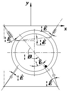
To analyze the transient state of the industrial washing machine, the mechanical model is established as shown in Fig. 1(c) and Fig. 1(d). It can be seen that the vibration isolation system of the industrial washing machine is mainly composed of suspension springs and air dampers for dynamic balance. In theoretical research, the mechanical model can be formulated on the basis of the rigid body assumption and small displacement assumption. According to the structural and state model illustrated, define as the eccentric mass, as the spring stiffness, and as the damping coefficient respectively.
The dynamic characteristics of the vibration isolation system of industrial washing machines directly determine the operational stability, structural reliability and operating noise level of the equipment, and the analysis of its dynamic response is the core premise for the optimal design and vibration control of the equipment. However, since the vibration isolation system is a multi-degree-of-freedom coupled vibration system, its vibration state has strong uncertainty, which brings great challenges to the accurate solution of the key motion parameters of the system and seriously restricts the in-depth analysis of the dynamic characteristics of the vibration isolation system and the subsequent optimal design work. To solve this technical problem and realize the accurate description and quantitative analysis of the dynamic characteristics of the vibration isolation system, this paper adopts the Lagrange method to construct the dynamic model of the vibration isolation system for characterizing its dynamic response law. In the generalized coordinate system, the dynamic equation established based on the principle of Lagrange dynamics is shown in Eq. (1):
where , , and respectively stand for kinetic energy, potential energy, dissipation energy. Within the generalized coordinate system, the relevant parameters can be calculated through Eq. (2) to Eq. (4), and the vector loop algorithm is adopted for the calculation process:
where and respectively are cylinder mass and eccentric mass, and are inertia moment of cylinder part and eccentric mass, and are linear velocity of cylinder part and eccentric mass, is the angular velocity of spindle, is spring static deformation, and are dynamic deformation of left spring and right spring, and are displacement of left damper and right damper, stands for height variation of barycenter, is rotational angular displacement.
Fig. 1Schematic diagram of structural composition and operational status
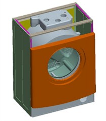
a) Overall structure
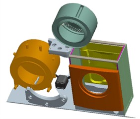
b) Segmented structure
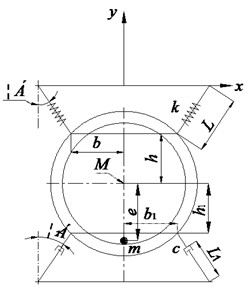
c) Static equilibrium state
d) Sperating state
Among them, can be expressed as in Eq. (5):
The relationship between and , , can be expressed as in Eq. (6)-Eq. (8):
2.2. Establishment of simulation analysis model
2.2.1. Establishment of rigid flexible coupling model for cabinet
According to the technical parameters, the limit dry load of the industrial washing machine studied in this paper is 100 kg. Considering extreme conditions in actual working conditions such as uneven distribution of eccentric mass and short-term overload, and combined with the requirement of safety margin, the limit mechanical working condition parameters adopted in this study are set as follows: eccentric mass (equivalent unbalanced load) of 110 kg, and maximum operating speed (dehydration stage) of 900 rpm. This working condition corresponds to the most severe mechanical conditions during the operation of the equipment, which can be used to evaluate the structural strength and dynamic response of the cylinder, cabinet and suspension system under extreme centrifugal load and eccentric impact.
The cabinet of the industrial washing machine is a thin-walled sheet metal part with low stiffness, which is prone to elastic deformation and has complex modal characteristics. Therefore, the establishment of a full-machine rigid-flexible coupling model is proposed. Setting key sheet metal structures such as the cabinet as flexible bodies and retaining the rigid body properties of other high-strength components can not only accurately capture the local stress concentration, elastic deformation and natural modes of the cabinet, but also restore the coupling relationship between structural elastic deformation and full-machine vibration, providing a reliable simulation basis for subsequent structural optimization, vibration control and fatigue analysis. The implementation method of the rigid-flexible coupling model is divided into two steps. Firstly, refined finite element meshing is performed on thin-walled parts such as the cabinet and outer cylinder, and their modal and stress information are calculated to generate a modal neutral file. Subsequently, the flexible body file is imported into the multi-body dynamics environment, assembled and constrained with rigid body components, connection units such as springs and dampers are set, and the limit eccentric load and maximum speed working conditions are applied. Finally, the cabinet stress, full-machine natural frequency and dynamic load at connection points are synchronously output through the coupling solver, achieving a balance between accuracy and efficiency.
Table 1The definition of material properties of cabinet
Material | Property | Density | Tensile strength | Yield strength | Elongation | Elastic modulus | Poisson’s ratio |
AISI 304 stainless steel | Value | 7.85 g/cm3 | 520 MPa | 355 MPa | 22 % | 220 GPa | 0.29 |
As a key component directly bearing the core load of an industrial washing machine, the inner cylinder has its material properties listed in Table 1. Loads are concentrated on critical positions such as the cylinder wall, stiffeners and shaft connecting seat, which easily gives rise to stress concentration. Furthermore, the inner cylinder is a thin-walled asymmetric structure with openings and flow deflectors. It features dense modal distribution and is prone to local resonance. Accurate acquisition of its local mechanical responses and modal characteristics cannot be achieved merely by full-machine analysis, whereas independent model analysis is capable of solving this problem pertinently. Compared with the global rigid-flexible coupling analysis of the cabinet, the separate finite element analysis of the inner cylinder enables refined mesh generation and targeted attention to high-stress dangerous regions, so as to accurately calculate the stress distribution, structural stiffness and natural modes. Meanwhile, it greatly reduces the model scale and computational cost, eliminates interference from other components of the complete machine, and improves the iteration efficiency of structural optimization for the inner cylinder.
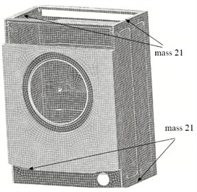
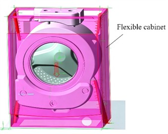
Rigid-flexible coupling processing of the industrial washing machine cabinet can be implemented in ADAMS. This requires the flexible cabinet model to finish modal analysis and coupling point definition in advance via ANSYS, as illustrated in Fig. 2(a). The MNF (Modal Neutral File) pre-calculated by ANSYS can be accurately invoked in the ADAMS software. Containing complete key information including the flexible body characteristics and modal parameters of the washing machine cabinet, the MNF file acts as the basic prerequisite for realizing rigid-flexible coupling conversion. The core of the processing procedure is to replace the cabinet, which is defined as a rigid body in initial modeling, with the flexible body structure corresponding to the MNF file. To ensure the accuracy of structural analysis and the reliability of simulation results, the setting rule of align flex body CM with CM of current part must be strictly followed in the critical conversion process from rigid body to flexible body. This enables the centroid of the flexible body to coincide perfectly with that of the original rigid body, so as to avoid deviations in subsequent dynamic analysis induced by centroid offset. Furthermore, the original constraint settings will fail and become invalid after rigid-flexible coupling operation. It is essential to readjust and reconfigure the constraint parameters, check and update the expired constraints item by item, and match the constraint conditions with the dynamic characteristics of the flexible body. Ultimately, the rigid-flexible coupling model consistent with the actual operating conditions of the industrial washing machine can be established, which lays a solid foundation for the subsequent dynamic analysis [10].
Fig. 2Establishment of cabinet simulation model
a) Flexible processing setting
b) Assembly of rigid flexible coupling
The Bin file saved in ADAMS stores the specific path information of the MNF file generated by ANSYS. As the core carrier for flexible body modeling, any change to the storage location of the MNF file will directly cause model loading failure and further interrupt the entire rigid-flexible coupling process. Therefore, the storage path of the MNF file must be fixed, and random movement or revision of the file is strictly prohibited. The modal selection of the flexible body is directly related to simulation efficiency and analysis accuracy. Combined with the actual operating conditions of the industrial washing machine and the calculation results of natural frequencies, the first four modes are selected in this paper. This scheme can not only cover the key vibration parameters to ensure analysis accuracy, but also avoid increased computational burden and reduced simulation efficiency caused by adopting excessive modes, realizing a balance between simulation accuracy and computational efficiency. During the whole dynamic analysis process, the Appearance attribute of the flexible body is not allowed to be modified. This attribute is directly correlated with the stress distribution and vibration characteristics of the flexible body. Arbitrary modification will result in abnormal stress display and distorted vibration simulation, which undermines the accuracy of subsequent structural strength verification.
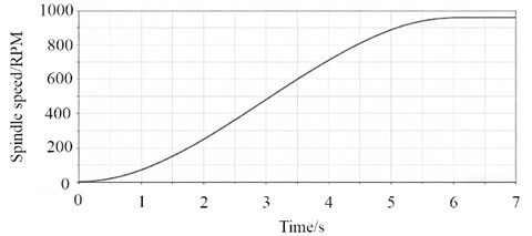
In the rigid-flexible coupling simulation model of the industrial washing machine, the spindle speed characteristic curve during the process from the main spindle starting from rest to steady-state dehydration is shown in Fig. 3. It can be observed that the curve exhibits a typical S-shaped dynamic acceleration characteristic. During the initial slow acceleration phase, the spindle speed increases gradually with the acceleration increasing progressively. During the rapid acceleration phase, the spindle speed increases approximately linearly while the acceleration remains at a relatively high level, before finally stabilizing at the set limit dehydration speed. In this study, this speed curve is adopted as the dynamic load input for spindle drive, which directly determines the dynamic variation law of the eccentric centrifugal load. The dynamic variation of the spindle speed drives the eccentric load to increase nonlinearly with time, which couples with the low-order modes of the flexible cabinet and may induce a dynamic stress amplification effect. Through the analysis of the full dynamic working process of the industrial washing machine from rest to the limit centrifugal load, the transient stress response characteristics of the flexible cabinet can be obtained, and the maximum stress value under dynamic working conditions can be further determined, providing a reliable simulation basis for subsequent structural optimization design and adjustment of vibration control parameters.
Fig. 3Main spindle speed characteristics
2.2.2. Establishment of finite element model for inner cylinder
The inner cylinder of an industrial washing machine serves as the core force-bearing component directly subjected to centrifugal force and is manufactured from stainless steel, whose material properties are presented in Table 2. Despite the excellent corrosion resistance, toughness and structural strength of the inner cylinder, it adopts an integral thin-walled sheet metal structure. Local stress concentration occurs at key positions such as stiffeners and shaft connection seats, endowing the structure with asymmetric characteristics. By simulating the distribution laws of stress and deformation of the high-speed rotating inner cylinder under the coupled effect of eccentric load and centrifugal force during the dehydration process, it can be verified whether the load-bearing capacity of the inner cylinder satisfies the design requirements under extreme working conditions. Furthermore, strength analysis enables the accurate localization of high-stress dangerous regions, providing a theoretical foundation for the structural optimization of the inner cylinder.
Table 2The definition of material properties of inner cylinder
Property | Density | Tensile strength | Yield strength | Elongation | Elastic modulus | Poisson’s ratio |
Value | 7.85 g/cm3 | 515 MPa | 205 MPa | 40 % | 193 GPa | 0.30 |
Modal analysis of the inner cylinder is an essential procedure to ensure the operational stability of industrial washing machines. From the perspective of analytical principle, modal analysis is based on vibration theory. By calculating modal parameters including natural frequencies and mode shapes of the inner cylinder, the resonance risk within the operating speed range can be assessed. When the natural frequency of the inner cylinder approaches or coincides with the equipment operating frequency (such as motor speed and excitation frequency caused by eccentric load), resonance will be triggered. This leads to aggravated vibration and increased noise of the inner cylinder, and long-term operation will exacerbate fatigue damage and shorten the service life. The modal analysis of the inner cylinder structure ensures its stable operation under prolonged complex working conditions, while balancing structural reliability and operational smoothness.
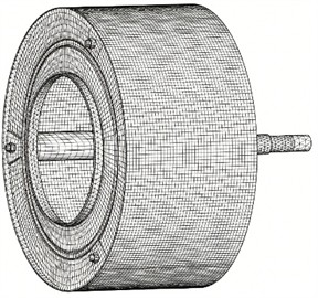
Fig. 4(a) presents the finite element meshing results of the inner cylinder of the industrial washing machine, showing the element discretization status of key structures such as the cylinder wall, shaft connection seat, and stiffeners. A structured meshing strategy with local refinement is employed in this work. The main thin-walled region of the inner cylinder is discretized using hexahedral solid elements, and regular element arrays are generated via the sweep meshing method to balance computational efficiency and overall mesh quality. Local mesh refinement is implemented for stress concentration regions such as stiffeners, hole edges, and shaft connection seats; by reducing the element size to increase local element density, high stress gradients can be accurately captured. To ensure mesh quality, key indicators including element aspect ratio and Jacobian determinant are strictly controlled during the meshing process, and distorted elements are optimized and corrected. Meanwhile, no fewer than two layers of elements are arranged in the thickness direction of the cylinder wall to guarantee the effective transmission of bending loads, thus establishing a reliable discretized model for subsequent strength and modal analyses.
Fig. 4Establishment of inner cylinder simulation model
a) Mesh division results
b) Setting of load and boundary conditions
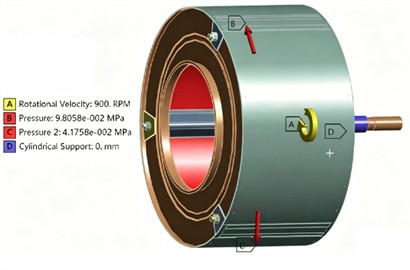
Fig. 4(b) illustrates the load and boundary condition settings of the inner cylinder simulation model, whose scheme is fully formulated based on the actual operating conditions and assembly constraints of the industrial washing machine. The specific simulation parameters are shown in Table 3. For load settings, a rotational angular velocity corresponding to the maximum operating speed of 900 rpm during the dehydration stage is applied to simulate the centrifugal inertia force induced by the eccentric mass inside the cylinder. Meanwhile, distributed pressure is adopted to equivalent working load effects, reproducing the load state under extreme dehydration conditions. Regarding boundary conditions, a cylindrical support constraint is imposed at the shaft of the inner cylinder to limit the radial and axial displacements of the shaft while releasing only the rotational degree of freedom, simulating the supporting effect of actual bearings and eliminating rigid body displacement. This setting scheme not only reproduces the actual stress and constraint state of the inner cylinder but also ensures the consistency between the simulation mechanical boundary and the actual operating conditions, providing a reliable premise for the accurate solution of stress distribution, deformation response, and modal characteristics.
Table 3The setting of simulation parameters for inner cylinder
Eccentric mass | Maximum rotational speed | Modal type | Duration of transient structural analysis | Modal order |
110 kg | 900 r/min | Constrained mode | 7 s | 4 |
2.3. Strength and modal analysis
2.3.1. Transient stress and modal characteristics analysis of cabinet
In the rigid-flexible coupling simulation model of the industrial washing machine, the stress distribution nephogram of the flexible cabinet at the instant of transient maximum stress (4.6 s) is shown in Fig. 5. As can be observed from the nephogram, the stress distribution of the cabinet exhibits a significant non-uniform characteristic. The maximum stress reaches 246.68 MPa, which is lower than the yield strength of the material. High stress concentration regions are mainly distributed in the top crossbeam connected with suspension springs and the front bottom corner points, which are the critical dangerous sections of the structure. The stress levels in large thin-walled areas such as the front door panel and side panels of the cabinet are relatively low, and the structure is dominated by elastic deformation as a whole without obvious local stress concentration. This distribution law clearly reflects the load transfer path: the eccentric centrifugal load is transmitted to the top and bottom support points of the cabinet through the suspension system, and then diffuses around along the sheet metal frame. As the load input points, the support points become the core areas of stress concentration.
Fig. 5Analysis results of maximum stress state of cabinet
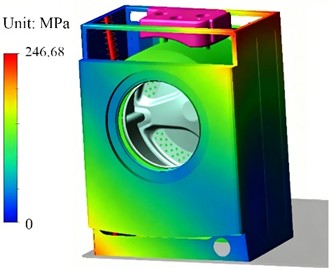
It can also be seen from the simulation results that the maximum stress of the cabinet does not occur at the moment of the maximum steady-state rotational speed during the dehydration stage. As a thin-walled sheet metal flexible structure, the cabinet has specific low-order natural frequencies. During the acceleration process of the main spindle, the excitation frequency of the eccentric load increases linearly with the rise of rotational speed. When the excitation frequency sweeps through a certain low-order natural frequency of the cabinet, a resonance-like effect is triggered, resulting in a significant reduction in the dynamic stiffness of the structure and a substantial amplification of the vibration response. Even if the centrifugal load has not reached its steady-state maximum value, the dynamic stress far exceeds the static level due to the resonance amplification effect. Meanwhile, in the rigid-flexible coupling model, there is a strong interaction between the elastic deformation of the cabinet, the rigid body motion of the outer cylinder and the dynamic response of the suspension system. The coupling among the cabinet modes, the eccentric excitation frequency of the outer cylinder and the natural frequency of the suspension system generates a dynamic stress amplification coefficient, which ultimately leads to the maximum stress level at this instant.
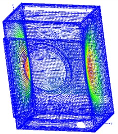
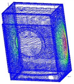
Fig. 6 presents the simulation results of the first four-order modes of the flexible cabinet of the industrial washing machine. It can be observed that the natural frequencies are distributed in the range of 64.89-96.44 Hz, and all mode shapes are dominated by the elastic deformation of thin-walled sheet metal structures. The natural frequency difference between the first and second modes is only 0.18 Hz, forming near-repeated frequency modes, which exhibit symmetric and antisymmetric bulging deformations of the side panels, respectively. The third-order mode shape shows bending deformation of the bottom frame and the lower part of the side panels, while the fourth-order mode shape corresponds to coupled deformation of overall torsion and high-order bulging of the side panels. Combined with the analysis of the operational excitation characteristics of the washing machine, there is a significant frequency difference between the natural frequencies of the cabinet and the fundamental frequency excitation of the main spindle during the dehydration stage. Although factors such as uneven distribution of eccentric mass, bearing clearance, and baffle impact will generate high-order harmonics in the excitation, the probability of fundamental frequency resonance is relatively low.
Fig. 6Simulation results of the first four – order modal shapes of cabinet
a) The first order (64.89 Hz)
b) The second order (65.07 Hz)
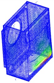
c) The third order (83.34 Hz)
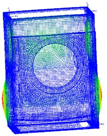
d) The fourth order (96.44Hz)
2.3.2. Static strength and modal analysis of inner cylinder
The stress field distribution nephogram of the inner cylinder of the industrial washing machine under the limit dehydration condition is shown in Fig. 7(a). As can be observed from the figure, the maximum stress of the inner cylinder is 186.39 MPa, which is lower than the yield strength and concentrated in the transition region between the shaft connection seat and the cylinder wall, meeting the strength requirements. The stress levels in the main cylinder wall, hole edges, and flow deflectors are relatively low. This distribution law arises from the coupling effect of the load transfer path and structural geometric characteristics. During the dehydration stage, the inner cylinder is subjected to eccentric centrifugal load, which converges to the shaft connection seat through the cylinder wall and is then transmitted to the bearing support system via the shaft. As the rigid connection interface between the cylinder wall and the shaft, the shaft connection seat triggers a stress concentration effect due to geometric discontinuity. Meanwhile, this region directly bears all the centrifugal load transmitted by the cylinder wall, becoming the core location of the stress peak; in contrast, the main cylinder wall exhibits relatively uniform and low stress distribution due to the elastic load-sharing effect of the thin-walled structure.
The deformation field distribution nephogram of the inner cylinder is shown in Fig. 7(b). The deformation distribution of the inner cylinder presents a radial gradient characteristic centered on the shaft. The maximum deformation is 2.93 mm, which occurs at the outer edge region of the cylinder wall far from the shaft, while the deformation in the shaft connection seat and the transition region between the cylinder wall and the shaft is extremely small, with almost no displacement. Since the outer edge of the cylinder wall is a free end, the thin-walled cylinder wall undergoes radial elastic expansion under the action of centrifugal inertia force, and the deformation accumulates with the increase of radius. The outer edge far from the shaft reaches the peak deformation due to the largest moment arm and the weakest constraint.
Fig. 7Static analysis results of inner cylinder components
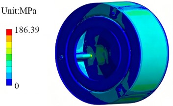
a) Analysis results of stress field
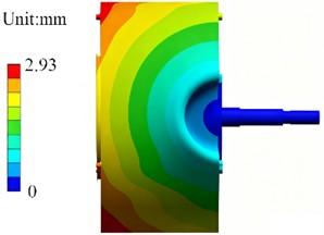
b) Analysis results of deformation field
Fig. 8Simulation results of the first four-order modal shapes of inner cylinder
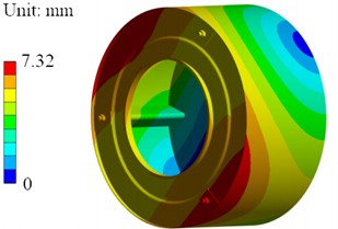
a) The first order (51.69 Hz)
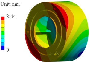
b) The second order (52.71 Hz)
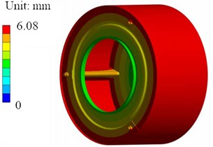
c) The third order (95.07 Hz)
d) The fourth order (112.25 Hz)
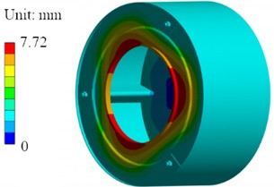
The simulation results of the first four-order modes of the inner cylinder of the industrial washing machine are shown in Fig. 8. The natural frequencies of each order are distributed in the range of 51.69-112.25 Hz, and all mode shapes are dominated by the elastic deformation of the cylinder wall without rigid body modes, reflecting the typical vibration characteristics of thin-walled rotating cylindrical structures. The first-order mode is axial bending vibration, with the mode shape showing unilateral bulging and opposite side indentation in the middle-rear section of the cylinder wall, reflecting the basic bending vibration characteristics of the inner cylinder under axial loads. The frequency difference between the second-order mode and the first-order mode is only 1.02 Hz, belonging to near-repeated frequency modes, and the mode shape presents antisymmetric bending deformation. The maximum deformation is distributed at the front and rear ends of the cylinder wall, which together with the first-order mode forms the first-order bending mode family of the inner cylinder, reflecting the symmetric vibration response of the thin-walled structure. The third-order mode is radial vibration, with the mode shape showing the deformation of overall radial expansion of the cylinder wall. The maximum deformation is concentrated in the middle-front section of the cylinder wall, reflecting the radial stiffness characteristics of the cylinder wall. The fourth-order mode is torsion-bending coupled vibration, with the mode shape presenting the composite deformation of circumferential torsion and axial bending of the cylinder wall. The maximum deformation is distributed in the middle-rear section of the cylinder wall, reflecting the torsional stiffness characteristics of the connection structure between the cylinder wall and the shaft.
2.4. Lightweight design
2.4.1. Definition of design variables and optimization objectives
The design variables of the industrial washing machine cabinet are shown in Fig. 9 and Table 4. The thickness of the side panel (P1_1), the thickness of the front panel (P1_2), the width of the groove (P1_3), and the height of the groove (P1_4) are selected as optimization variables, with reasonable upper and lower limits set around the initial design values. These variables are selected with the lightweight design objective (minimum mass, P1_5) as the core, while taking into account structural strength and dynamic characteristic constraints. Among them, the side panel and front panel are the main thin-walled load-bearing components of the cabinet; their thickness directly determines the amount of sheet metal material used, which is a key factor affecting the cabinet mass. Changes in the dimensions of the groove structure on the cabinet will alter the structural stiffness distribution and stress transfer path. To ensure that the strength and stiffness do not degrade, the boundary conditions require that the maximum stress (P1_6) does not exceed the initial stress peak, and the first-order natural frequency (P1_7) is not lower than the initial value. Optimization is required to find the optimal parameter combination to achieve mass minimization while satisfying the constraints.
Fig. 9Design variables of cabinet
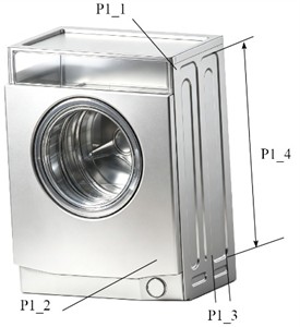
Fig. 10Design variables of inner cylinder
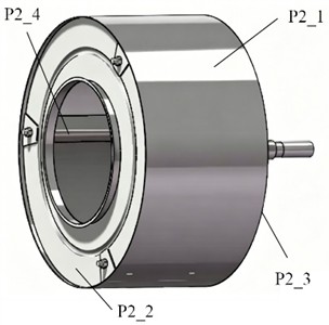
The design variables of the industrial washing machine inner cylinder are shown in Fig. 10 and Table 5. The thickness of the cylinder wall (P2_1), the thickness of the front panel (P2_2), the thickness of the back panel (P2_3), and the height of the lifting rib (P2_4) are selected as optimization variables, with the value range covering approximately ±20 % of the initial design values. The selection of these variables is closely centered on the lightweight design objective of the inner cylinder (minimum mass, P2_5), while meeting the requirements of strength and modal constraints. The cylinder wall, front and rear end caps are the core load-bearing components of the inner cylinder, bearing the main centrifugal load, and their thickness directly affects the overall mass and stiffness. Similarly, the boundary conditions require that the maximum stress (P2_6) does not exceed the initial stress peak, and the first-order natural frequency (P2_7) is not lower than the initial value, so as to complete the lightweight design without reducing structural reliability.
Table 4Design variables for cabinet component
Name of parameter | Structural description | Initial value / mm | Minimum value / mm | Maximum value / mm |
P1_1 | Thickness of side panel | 1.5 | 1.2 | 1.8 |
P1_2 | Thickness of the front panel | 1.0 | 0.8 | 1.2 |
P1_3 | Width of groove | 15.5 | 12 | 18 |
P1_4 | The height of the groove | 912.4 | 650 | 1100 |
Table 5Design variables of inner cylinder component
Name of parameter | Structural description | Initial value / mm | Minimum value / mm | Maximum value / mm |
P2_1 | Thickness of the cylinder | 0.5 | 0.25 | 0.75 |
P2_2 | Thickness of the front panel | 1.0 | 0.8 | 1.2 |
P2_3 | Thickness of the back panel | 1.0 | 0.8 | 1.2 |
P2_4 | Height of lifting rib | 30 | 27 | 33 |
2.4.2. Establishment of response surface function
The Kriging model is a non-parametric interpolation method based on spatial statistics theory. Its core principle is to construct the covariance function of sample points, considering both the global trend of variables and local spatial correlation, to achieve unbiased optimal estimation of response values at unknown points. A prominent feature of this model is its ability to accurately capture nonlinear, multi-modal, or locally fluctuating relationships between design variables and responses [11-13]. It is particularly suitable for engineering optimization scenarios with limited sample data and complex response surface characteristics, combining interpolation accuracy with prediction robustness. In this study, there exist complex nonlinear correlations between the responses (e.g., mass, stress, natural frequency) of the research object and the design variables, such as stiffness-mass coupling and stress concentration effects. The Kriging model can effectively fit such multi-variable coupled response characteristics, providing an efficient surrogate model support for subsequent lightweight optimization.
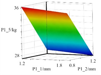
The response surface models of the cabinet design variables fitted based on the Kriging model are shown in Fig. 11, which illustrate the functional relationships between design variables and the cabinet’s mass (P1_5), maximum stress (P1_6), and first-order natural frequency (P1_7). It can be observed that the mass response surfaces exhibit a significantly linear-dominated characteristic. The thickness of the side panel and front panel show a positive linear correlation with mass: an increase in plate thickness directly increases the material volume, resulting in planar response surfaces. Conversely, the groove width and groove height show a negative linear correlation with mass: an increase in groove size reduces mass through material removal effects, and the response surfaces are also approximately planar, reflecting the monotonic linear correlation between mass and geometric parameters. The stress response surfaces, however, show obvious nonlinear characteristics. When the plate thickness changes, the stress first decreases with the reduction of plate thickness, then rises again due to insufficient stiffness, forming a low-stress valley region. When the groove size changes, the stress distribution is affected by the coupling effect of structural stiffness distribution and stress transfer path, presenting a curved fluctuation characteristic. This indicates that there are nonlinear extreme points in the sensitivity of stress to geometric parameters, and the optimal interval needs to be analyzed in combination with constraints. When the thickness of the side panel and front panel changes, the response surface of the natural frequency presents a V-shaped curved fluctuation. A frequency trough appears near the range of smaller plate thickness, reflecting the attenuation of the natural frequency when the thin-walled structure lacks sufficient stiffness. Although increasing the plate thickness improves the stiffness, the mass increases simultaneously, leading to a stiffness-mass coupling effect that makes the frequency response nonlinear. When the groove size changes, the response surface of the natural frequency is curved, as the geometric parameters of the groove affect the natural frequency by changing the local stiffness distribution.
Fig. 11The response surface models of cabinet
a) Response surface of P1_1 and P1_2 for P1_5
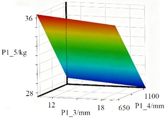
b) Response surface of P1_3 and P1_4 for P1_5
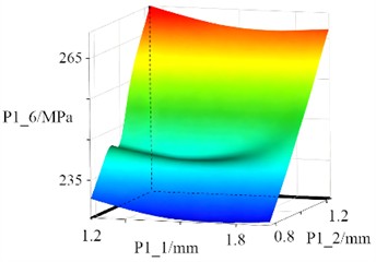
c) Response surface of P1_1 and P1_2 for P1_6
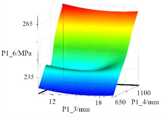
d) Response surface of P1_3 and P1_4 for P1_6
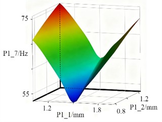
e) Response surface of P1_1 and P1_2 for P1_7
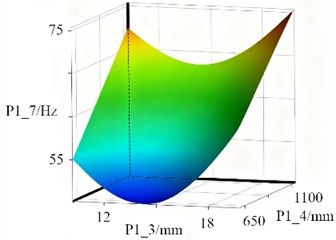
f) Response surface of P1_1 and P1_2 for P1_7
The response surface models of design variables for the industrial washing machine inner cylinder, fitted based on the Kriging model, are shown in Fig. 12, which clearly reveal the coupling relationships between design variables and various responses, providing surrogate model support for the lightweight optimization of the inner cylinder.
Fig. 12The response surface models of inner cylinder
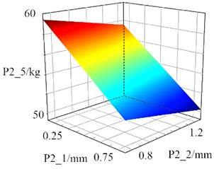
a) Response surface of P2_1 and P2_2 for P2_5
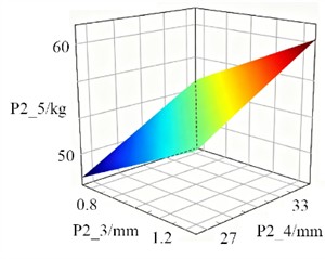
b) Response surface of P2_3 and P2_4 for P2_5
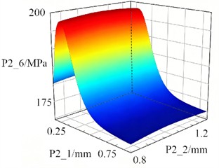
c) Response surface of P2_1 and P2_2 for P2_6
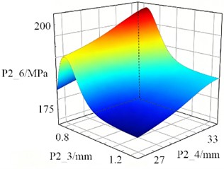
d) Response surface of P2_3 and P2_4 for P2_6
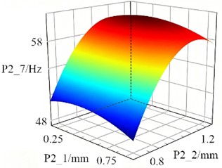
e) Response surface of P2_1 and P2_2 for P2_7
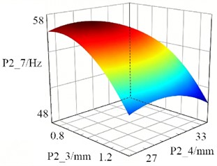
f) Response surface of P2_1 and P2_2 for P2_7
The response surfaces of the inner cylinder mass exhibit a prominent linear-dominated characteristic, reflecting the direct monotonic relationship between geometric parameters and mass. The cylinder wall thickness, front panel thickness, and back panel thickness show positive linear correlations with mass; an increase in plate thickness directly raises the material volume, resulting in planar response surfaces. The height of the lifting rib also shows a positive linear correlation with mass; an increase in the height of the lifting rib increases the material usage, and the corresponding response surface is approximately planar. The response surfaces of the maximum stress of the inner cylinder exhibit strong nonlinear characteristics, reflecting the complex coupling relationships between stress and design variables. When the cylinder wall thickness and front panel thickness change, the stress does not vary monotonically with plate thickness. When the plate thickness is too small, the structural stiffness is insufficient, deformation under centrifugal loads intensifies, and the stress concentration effect is significant, leading to an increase in stress. As the plate thickness increases, the stiffness improves, and the stress first decreases to a valley range. However, when the plate thickness is excessively large, changes in the structural stiffness distribution will alter the stress transfer path, causing the stress to rise instead and forming curved fluctuation characteristics. The influences of the back panel thickness and lifting rib height are also nonlinear. Changes in the height of the lifting rib will alter the local stiffness and mass distribution of the inner cylinder, thereby affecting the location and level of stress concentration. The multi-modal characteristics of the response surfaces indicate that there are multiple nonlinear extreme points in the sensitivity of stress to geometric parameters, requiring the determination of the optimal parameter range in combination with constraint conditions. The response surfaces of the first-order natural frequency of the inner cylinder present typical nonlinear curved characteristics, reflecting the coupling effect between stiffness and mass. When the plate thickness is small, insufficient stiffness is the dominant factor, and the frequency decreases as the plate thickness increases. As the plate thickness further increases, the influence of improved stiffness exceeds that of increased mass, and the frequency begins to rise again, forming curved fluctuations. Changes in the back panel thickness and lifting rib height also affect the natural frequency by altering the local stiffness and mass distribution. An increase in the height of the lifting rib simultaneously improves the local stiffness and mass, leading to nonlinear variations in the frequency response.
2.4.3. Discussion on optimization results
According to the requirements of lightweight design, the optimization mathematical model is constructed as shown in Eq. (9) and Eq. (10). It can be seen that this model transforms the multi-objective optimization problem into a lightweight analysis problem with mass minimization P5() as the objective. The constraint conditions include: the maximum structural stress P6() does not exceed the initial stress peak , and the first-order natural frequency P7() is not lower than the initial natural frequency . Meanwhile, the design variables must take values within the preset upper and lower limits, aiming to achieve mass minimization by adjusting geometric parameters while ensuring that the structural strength and dynamic characteristics are not inferior to those of the initial design:
Considering the characteristics of the optimization mathematical model, the Sequential Quadratic Programming (SQP) algorithm is selected for solving. SQP is a classic and efficient algorithm for nonlinear constrained optimization problems. Its core principle is that, in each iteration, the Lagrangian function of the original optimization problem is approximated as a quadratic function and the constraints are linearized around the current iteration point. A quadratic programming (QP) subproblem is constructed and solved to obtain the search direction, and then the step size is determined through line search to gradually approach the optimal solution. This algorithm features fast convergence rate and high solution accuracy, can effectively handle equality and inequality constraints in engineering optimization, and exhibits strong robustness to nonlinear objective and constraint functions. It is widely applied in constrained nonlinear optimization scenarios such as structural lightweight optimization.
Table 6The optimization results of cabinet
Parameters | P1_1/ mm | P1_2 /mm | P1_3/ mm | P1_4/ mm | P1_5/ kg | P1_6/ MPa | P1_7/ Hz | Weight loss rate / % |
Initial value | 1.5 | 1.0 | 15.5 | 912.4 | 34.45 | 246.68 | 64.89 | / |
Optimization scheme | 1.32 | 0.91 | 17.33 | 904.10 | 30.67 | 245.52 | 64.89 | 11.0 % |
The lightweight design results of the cabinet and inner cylinder are shown in Table 6 and Table 7, respectively. It can be seen that both have achieved significant mass reduction while strictly satisfying all constraints of the optimization mathematical model, verifying the effectiveness of the model. After optimization, the mass of the cabinet decreased from 34.45 kg to 30.67 kg with a weight reduction rate of 11.0 %, and the mass of the inner cylinder decreased from 29.42 kg to 26.53 kg with a weight reduction rate of 9.8 %. In summary, the optimization results of both the cabinet and inner cylinder have effectively achieved the lightweight objective under the premise that structural strength and dynamic characteristics are not inferior to those of the initial design, fully meeting the requirements of the optimization mathematical model.
Table 7The optimization results of inner cylinder
Parameters | P2_1/ mm | P2_2 /mm | P2_3/ mm | P2_4/ mm | P2_5/ kg | P2_6/ MPa | P2_7/ Hz | Weight loss rate / % |
Initial value | 0.5 | 1.0 | 1.0 | 30 | 29.42 | 73.4 | 22.8 | – |
Optimization scheme | 0.41 | 1.17 | 0.87 | 28.85 | 26.53 | 73.2 | 22.8 | 9.8% |
3. Dynamics analysis and optimization
3.1. Analysis of centroid displacement and load response
Based on the rigid-flexible coupling model of the industrial washing machine, the displacement-time curve of the center of mass of the inner cylinder can be obtained, as shown in Fig. 13. This curve reflects the vibration response of the inner cylinder throughout the entire process from start-up acceleration to stable dehydration under static balance conditions. The curve exhibits the typical three-stage characteristics of start-up transient, transitional resonance, and steady-state operation. The period of 0-1 s corresponds to the start-up transient stage, during which the displacement of the center of mass first rises positively to approximately 15 mm and then reaches a reverse peak of –30 mm, reflecting the transient response coupled by the start-up impact of the shaft system and the initial elastic deformation of the flexible inner cylinder at low rotational speeds. The period of 1-5 s is the transitional stage. As the rotational speed continues to increase, the envelope of the displacement oscillation gradually expands, and the vibration amplitude of the center of mass is significantly amplified with the rise of the excitation frequency. The system enters the steady-state operation stage during 5-7 s, where the amplitude of the displacement oscillation tends to be stable, and no continuous divergence of the fluctuation amplitude occurs.
Fig. 13Displacement curve of the center of mass of inner cylinder
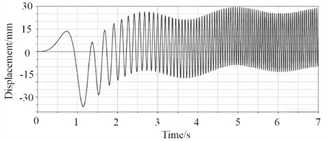
The displacement fluctuation in the start-up stage originates from the torsional vibration of the shaft system. At this time, the excitation frequency is much lower than the natural frequency of the system, and the response is dominated by transient impact. The amplitude amplification in the transitional stage is due to the excitation frequency gradually approaching the natural frequency of the vibration isolation system, triggering a resonance-like effect. In the steady-state operation stage, after the rotational speed exceeds the critical speed, the system enters a supercritical state, where the excitation frequency is higher than the natural frequency of the vibration isolation system, and the vibration response tends to be steady-state. Moreover, the static balance condition eliminates the additional excitation caused by initial eccentricity, keeping the displacement amplitude stable within a controllable range. This curve verifies that the dynamic characteristics of the inner cylinder after lightweight optimization meet the design requirements, no resonance occurs at the operating speed, and the vibration response is stable and controllable. It also reflects the accurate capture capability of the rigid-flexible coupling model for the full-cycle dynamic behavior.
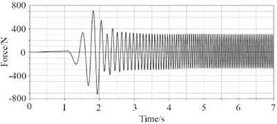
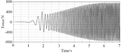
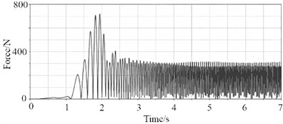
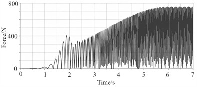
In the vibration isolation system, the force curves of the spring, damper, and the upper and lower suspension points of the cabinet are shown in Fig. 14, which fully present the dynamic load response of the industrial washing machine throughout the entire dehydration cycle. The responses of the spring force and damping force reflect the functional division of the vibration isolation system. The spring force exhibits sharp peaks during the transitional resonance stage and drops to approximately ±200 N in the steady-state stage, mainly providing restoring force through elastic deformation to constrain the vibration amplitude. The damping force, proportional to the vibration velocity, rises rapidly with the amplification of vibration in the resonance region and maintains a relatively high amplitude of ±800 N in the steady-state stage, dominating the dissipation and attenuation of vibration energy. The two components jointly achieve the suppression of resonance impact and the control of steady-state vibration. The forces on the upper and lower suspension points of the cabinet show significant differences due to different load transfer paths. The peak force on the upper suspension point is concentrated in the resonance stage, with a steady-state amplitude of approximately ±300 N. The lower suspension point, located close to the rotating shaft, bears the directly superimposed loads of centrifugal force and shaft system vibration. It has a longer rising period of force values in the transitional stage and a steady-state amplitude of ±800 N, reflecting the load-bearing division of labor among different nodes. Overall, no divergence or overload occurs in the forces of all components, verifying the dynamic reliability of the vibration isolation system after lightweight optimization, and also demonstrating the accurate capture capability of the rigid-flexible coupling model for the load transfer process.
Fig. 14Force curves of springs, dampers, and suspension points
a) Changes in spring force
b) Changes in damping force
c) Changes in force on the upper suspension point
d) Changes in force on the lower suspension point
3.2. Optimization of vibration response characteristics
For industrial washing machines, if the vibration amplitude of the center of mass of the inner cylinder is too large, it will cause violent shaking of the vibration isolation system [14, 15]. In this case, the control system often limits the dehydration speed or reduces the speed midway, resulting in insufficient centrifugal dehydration, high residual moisture in clothes, and a prolonged washing cycle. In addition, excessive vibration amplitude will also cause the machine body to shake and shift, accompanied by strong mechanical noise. To address this problem, an optimization scheme for the vibration isolation system is proposed. The goal of the optimized design is to find a coordinated matching scheme by solving the design variables, aiming to reduce the vibration amplitude of the center of mass of the inner cylinder without increasing the peak response of the spring force load. The core design variables of the vibration isolation system are defined as spring stiffness and damping coefficient, with their value ranges shown in Table 8. These two parameters jointly determine the vibration isolation performance through nonlinear interaction. Spring stiffness regulates resonance risk and spring force level by affecting the natural frequency of the system. Low stiffness is prone to cause resonance impact, while high stiffness will lead to a rebound in spring force due to the linear relationship. The damping coefficient regulates vibration energy dissipation and displacement transmissibility under subcritical operating conditions by affecting the damping ratio. Low damping is difficult to suppress resonance amplification, while high damping will exacerbate displacement amplification. This value range covers low, medium, and high parameter intervals.
Table 8Design variables for spring and damper
Name of parameter | Parameter description | Initial value / mm | Minimum value / mm | Maximum value / mm |
Spring stiffness | 25 | 10 | 40 | |
Damping coefficient | 40 | 20 | 60 |
The response surface model of spring force, as shown in Fig. 15(a), presents a saddle-shaped surface, revealing the nonlinear interaction effect of spring stiffness and damping coefficient on spring force. When the damping coefficient is fixed, the spring force shows a trend of first decreasing and then increasing as the stiffness increases. The influence of damping varies with the stiffness level: increasing damping at low stiffness can significantly reduce the spring force, while increasing damping at high stiffness will instead cause the force value to rise. Overall, there exists a coordinated matching range that balances stiffness and damping, which can effectively reduce the peak spring force. The response surface model of the center-of-mass displacement of the inner cylinder, as shown in Fig. 15(b), exhibits a monotonically rising slope shape. Overall, the vibration isolation system has effective design variables that enable finding a balance within the ranges of stiffness coefficient and damping coefficient. This balance can not only avoid component fatigue caused by excessive spring force but also prevent the operation stability from being affected by excessive displacement amplification, providing a clear compromise design direction for the optimization of vibration isolation parameters.
Fig. 15Proxy model for vibration optimization
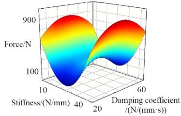
a) Response surface of force model
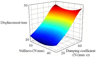
b) Response surface of displacement model
The optimization mathematical model for the vibration isolation system, as shown in Eq. (11) and Eq. (12), is established to seek the optimal solution for the spring stiffness coefficient and damping coefficient . Its objective is to minimize the maximum vibration amplitude under the constraint that the maximum spring force does not exceed its initial value :
Through iterative calculation [16, 17], the curves of the displacement amplitude of the inner cylinder’s center of mass as a function of frequency are obtained and presented in Fig. 16. It can be observed that the original vibration isolation system (before optimization) has two distinct resonance peaks at approximately 5 Hz and 30 Hz, with displacement amplitudes reaching nearly 10 mm and 20 mm respectively, indicating a pronounced resonance amplification effect. After optimization (where the design variables are adjusted to a spring stiffness of 26.76 N/mm and a damping coefficient of 37.78 N/(mm·s)), the amplitudes of these two resonance peaks are substantially reduced: the low-frequency peak drops to approximately 3 mm, and the high-frequency peak to approximately 8 mm, corresponding to reductions of 67 % and 58 % respectively. Additionally, the resonance peaks exhibit a more gradual profile, demonstrating that the coordinated matching of stiffness and damping effectively suppresses vibration amplification within the resonance region.
Fig. 16Vibration amplitude comparison before and after optimization
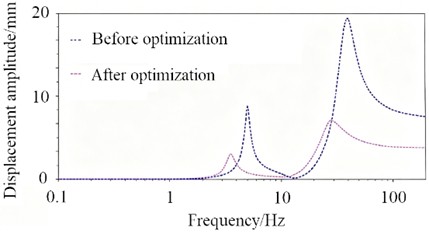
Across the entire frequency range, the displacement amplitudes of the optimized response curve are significantly lower than those prior to optimization across the start-up, acceleration, and dewatering operating phases. This optimization scheme avoids start-up transient impacts and eliminates speed reduction issues caused by excessive vibration during dewatering, thereby improving dewatering efficiency while reducing the impact of vibrational loads on the lightweight structure. The results confirm that this parameter combination effectively improves the vibration characteristics of the inner cylinder’s center of mass while controlling the peak spring force load, providing robust dynamic performance support for the system’s stable and efficient operation.
4. Conclusions
1) The effectiveness of the Kriging model and SQP algorithm in structural optimization was verified through strength analysis, modal characteristic analysis and lightweight design of the main load-bearing components (cabinet and inner cylinder) of industrial washing machines. The lightweight optimization of the cabinet and inner cylinder strictly met the strength and modal constraint conditions, achieving weight reduction rates of 11.0 % and 9.8 % respectively. The contradiction between lightweight design and structural reliability was resolved effectively. The optimized design not only reduced material costs and energy consumption, but also ensured the working performance of load-bearing components under extreme operating conditions, offering a feasible solution for the lightweight design of industrial washing machines.
2) Dynamic response analysis based on the rigid-flexible coupling model and finite element model indicated that the entire dehydration process of industrial washing machines followed three typical stages: start-up transient state, transitional resonance and steady-state operation. High-stress regions of the cabinet were concentrated on the crossbeams connected to suspension springs and front bottom corners, while those of the inner cylinder were located in the transition area between the shaft connecting seat and cylinder wall. The modal characteristics of both components avoided the excitation frequency corresponding to the operating speed, with no obvious resonance risk. In the vibration isolation system, springs and dampers functioned cooperatively: springs provided elastic restoring force and dampers dissipated vibration energy. The upper and lower suspension points presented differentiated force characteristics due to distinct load transfer paths, and no overload phenomenon occurred on all components, which verified the dynamic reliability of the system after lightweight design.
3) The optimization of vibration response for the vibration isolation system effectively solved the problem of excessive centroid vibration amplitude of the inner cylinder. After the coordinated matching of optimized spring stiffness of 26.76 N/mm and damping coefficient of 37.78 N/(mm·s), the low-frequency and high-frequency resonance peak amplitudes of the inner cylinder centroid vibration were reduced by 67 % and 58 % respectively, and the vibration amplitude across the full frequency range was decreased remarkably. Without increasing the peak load response of spring force, the optimization scheme suppressed resonance amplification effectively and avoided speed reduction caused by excessive vibration during the dehydration stage, thus improving dehydration efficiency. Meanwhile, the impact of vibrational load on lightweight structures was alleviated. This research provides dynamic performance support for the stable, efficient and low-noise operation of industrial washing machines, and also verifies the engineering practicability of the adopted model and optimization method.
References
-
F. Hashemian, X. Deng, Y. Wang, S. Kim, and R. Vaidhyanathan, “A comprehensive study of the effects of various design variables on the dynamic behavior and vibration characteristics of a front-loading washing machine,” Noise and Vibration Worldwide, Vol. 54, No. 9, pp. 477–491, Sep. 2023, https://doi.org/10.1177/09574565231194312
-
J. Park, S. Jeong, and H. Yoo, “Dynamic modeling of a front-loading type washing machine and model reliability investigation,” Machines, Vol. 9, No. 11, p. 289, Nov. 2021, https://doi.org/10.3390/machines9110289
-
E. Proner, E. Mucchi, and R. Tovo, “A relationship between fatigue damage estimation under multi-axis and single-axis random vibration,” Mechanical Systems and Signal Processing, Vol. 215, p. 111402, Apr. 2024, https://doi.org/10.1016/j.ymssp.2024.111402
-
Y. Jiao, K. Song, and J. Su, “Research on vibration characteristics of industrial washing machines based on numerical simulation,” Journal of Mechanical Science and Technology, Vol. 39, No. 11, pp. 6601–6611, Nov. 2025, https://doi.org/10.1007/s12206-025-1009-4
-
C. Choi, Y. Kwon, D. Kang, C. Kim, and S. Jung, “Development of washing machine dehydration unbalance control specifications through Bayesian optimization,” Applied Sciences, Vol. 15, No. 3, p. 1632, Feb. 2025, https://doi.org/10.3390/app15031632
-
F. Hashemian, H. Yang, Y. Wang, X. Deng, S. Kim, and R. Vaidhyanathan, “Parametric dynamic simulation and Bayesian design optimization of a front-loading washing machine,” Journal of Vibration Engineering and Technologies, Vol. 12, No. S1, pp. 41–62, 2024, https://doi.org/10.1007/s42417-024-01401-4
-
S. Mendoza-Flores, F. Velázquez-Villegas, and F. Cuenca-Jiménez, “Optimization of a horizontal washing machine suspension system: studying a 7 DOF dynamic model using a genetic algorithm through a bounding box fitness function,” Journal of Vibration Engineering and Technologies, Vol. 12, No. 4, pp. 6865–6884, Aug. 2024, https://doi.org/10.1007/s42417-024-01288-1
-
J.-S. Jeong, J.-H. Sohn, C.-J. Kim, and J.-H. Park, “Dynamic analysis of top-loader washing machine with unbalance mass during dehydration and its validation,” Journal of Mechanical Science and Technology, Vol. 37, No. 4, pp. 1675–1684, Apr. 2023, https://doi.org/10.1007/s12206-023-0309-9
-
W. Yu Wen and T. Jia Hui, “Dynamic analysis of elliptical vibrating screen based on disc motor,” Australian Journal of Mechanical Engineering, Vol. 21, No. 2, pp. 418–427, Mar. 2023, https://doi.org/10.1080/14484846.2020.1851867
-
J. Lu, B. Li, W. Ge, C. Tan, and B. Sun, “Analysis and experimental study on servo dynamic stiffness of electromagnetic linear actuator,” Mechanical Systems and Signal Processing, Vol. 169, No. 15, p. 108587, Nov. 2021, https://doi.org/10.1016/j.ymssp.2021.108587
-
H. K. Celik, I. Akinci, N. Caglayan, and A. E. W. Rennie, “Structural strength analysis of a rotary drum mower in transportation position,” Applied Sciences, Vol. 13, No. 20, p. 11338, Oct. 2023, https://doi.org/10.3390/app132011338
-
S. Vulovic, M. Zivkovic, A. Pavlovic, R. Vujanac, and M. Topalovic, “Strength analysis of eight-wheel bogie of bucket wheel excavator,” Metals, Vol. 13, No. 3, p. 466, Feb. 2023, https://doi.org/10.3390/met13030466
-
H. D. Chalak, A. M. Zenkour, and A. Garg, “Free vibration and modal stress analysis of FG-CNTRC beams under hygrothermal conditions using zigzag theory,” Mechanics Based Design of Structures and Machines, Vol. 51, No. 8, pp. 4709–4730, Aug. 2023, https://doi.org/10.1080/15397734.2021.1977659
-
Z. Liao, Q.-H. Wang, H. Xie, J.-R. Li, X. Zhou, and P. Hua, “Optimization of robot posture and workpiece setup in robotic milling with stiffness threshold,” IEEE/ASME Transactions on Mechatronics, Vol. 27, No. 1, pp. 582–593, Mar. 2021, https://doi.org/10.1109/tmech.2021.3068599
-
A. B. Nitalikar, Prof. R. D. Kulkarni, and Prof. A. Z. Patel, “Structural and finite element analysis of steering yoke of an automobile,” International Journal of Engineering and Management Research, Vol. 10, No. 5, pp. 68–74, Oct. 2020, https://doi.org/10.31033/ijemr.10.5.13
-
C. Wei, C. Li, X. Huang, J. Liu, and Y. Wang, “Amplitude-only feedback iterative optimization algorithm for phase-only holograms,” Applied Optics, Vol. 65, No. 10, p. D88, Apr. 2026, https://doi.org/10.1364/ao.586360
-
S. Bose, “Comparative performance analysis on WEDM responses for titanium matrix composite using novel multi-objective optimization algorithms,” National Academy Science Letters, Vol. 48, No. 2, pp. 251–257, Sep. 2024, https://doi.org/10.1007/s40009-024-01463-8
About this article

The paper is supported by provincial scientific research projects (62874155).
The datasets generated during and/or analyzed during the current study are available from the corresponding author on reasonable request.
The authors declare that they have no conflict of interest.

