Abstract
Deep rocks subjected to cyclic loading under high-stress conditions exhibit both load-dependent and time-dependent behavior. This study proposes a novel cyclic loading-unloading constitutive model that accounts for time effects during unloading. Cyclic loading-unloading tests at three loading rates were performed on marble specimens, with acoustic emission (AE) monitoring used to validate the model. The results show that lower loading rates produce shorter fatigue lives and more pronounced time effects. Before failure, AE signals are concentrated primarily near the upper stress limit in each cycle, although substantial AE activity is also detected during the early unloading stage. The proposed model accurately reproduces the stress-strain response throughout loading and unloading. For loading rates of 250, 500, and 1000 N/s, the maximum peak-stress errors are 1.5 %, 0.35 %, and 0.6 %, respectively. The calculated cumulative plastic strains also agree closely with the experimental value, with errors ranging from –3 % to 6 %. In addition, the model parameters exhibit clear and consistent evolutionary trends.
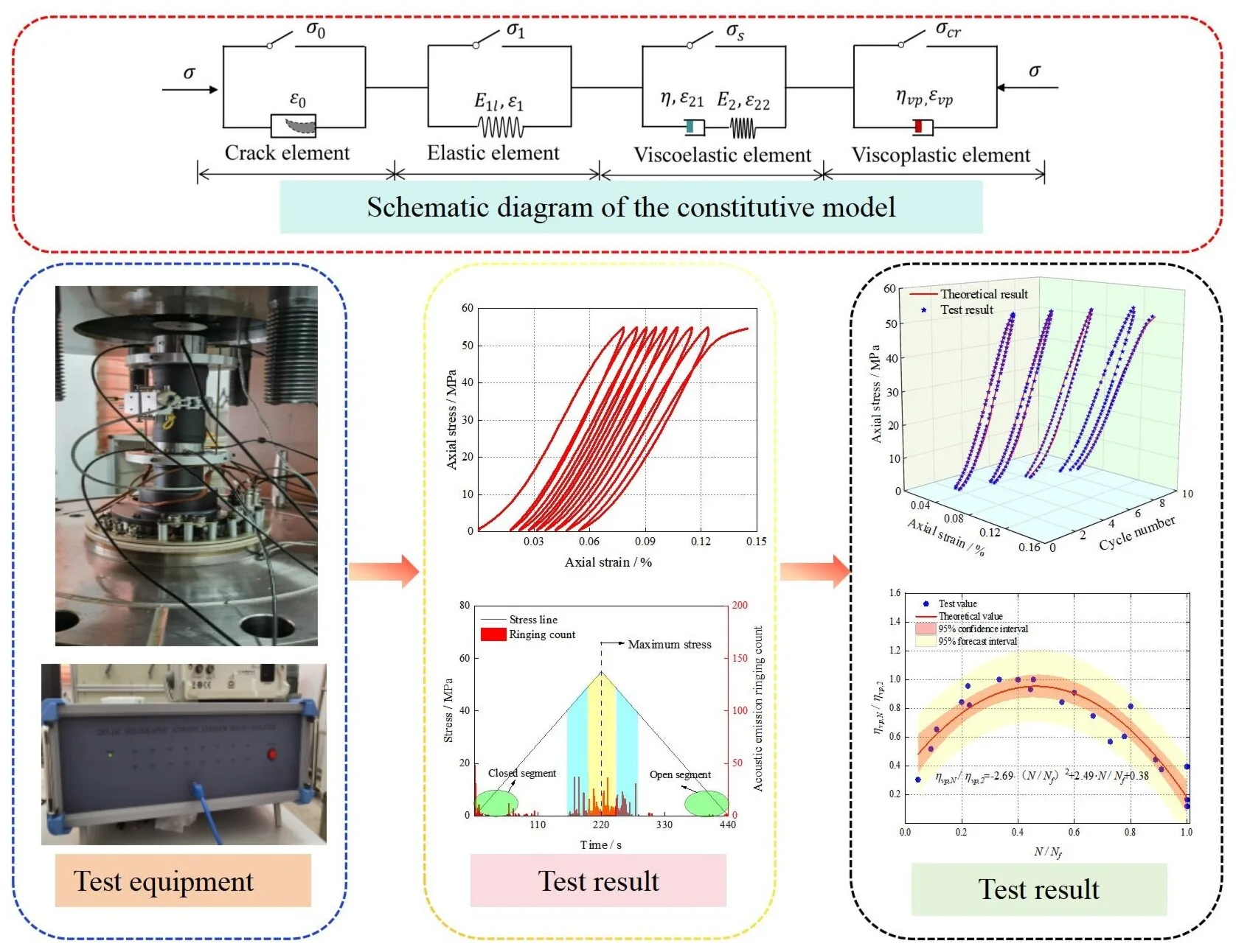
Highlights
- Cyclic loading and unloading tests of marble at different loading rates are carried out.
- Based on the test results, the characteristics of cyclic number and AE signals is analyzed.
- A novel constitutive model considering time effects under high-stress conditions during cyclic loading and unloading is established.
1. Introduction
As shallow resources become depleted, the development of deep resources has become an increasingly important direction for engineering and technological development worldwide. During the excavation of deep rock masses, rock surrounding free surfaces or pillars are often subjected to axial loads under high-stress conditions. Repeated mining operations subject rock masses to periodic cyclic loading and unloading, causing deformation to accumulate continuously. Once the accumulated deformation exceeds a critical threshold, the rock may fail and lose its load-bearing capacity [1-2]. Cyclic loading and unloading are also common in underground gas-storage facilities and pumped-storage projects that use abandoned mines [3-4]. Therefore, understanding the mechanical behavior of deep rock under cyclic loading and unloading is essential for ensuring engineering safety [5-6]. Numerous studies have investigated the mechanical behavior of rock under cyclic loading and unloading [7-9]. Zhang et al. [10] examined rocks subjected to different cyclic loading-unloading paths and found that repeated cycling reduced deformation resistance, with the magnitude of the reduction depending on the loading path. Zhang et al. [11] investigated the deformation and mechanical responses of layered rock and analyzed the evolution of cumulative energy under cyclic loading. Wang et al. [12] evaluated the effects of loading frequency and amplitude on the cyclic fatigue behavior of salt rock used for underground gas storage. Wang et al. [13] showed that disturbance frequency affected volumetric deformation, fatigue life, energy dissipation, and damage accumulation. Liu et al. [14] found that lower loading frequencies, higher maximum stresses, and larger amplitudes shortened fatigue life, whereas the failure mode was independent of the loading parameters. Other studies have demonstrated that rock mechanical properties are also influenced by the fatigue stress level and cyclic-load waveform [15-17].
Rock failure induced by cyclic loading is macroscopically manifested as increasing deformation. Understanding the deformation of high-stress rock under cyclic loading is therefore essential for the safety of rock-engineering projects [18]. Various fatigue constitutive models have been developed to describe this behavior. Xiao et al. [19-20] proposed an inverted S-shaped damage-accumulation model based on the assumption that fatigue strain evolves monotonically. Zhu et al. [21] developed a fatigue-damage model that predicts fatigue life by incorporating initial and thermal damage into the complete stress-strain curve. He et al. [22] proposed a fatigue constitutive model that accounts for stress amplitude, loading rate, and stress-holding time. Zhu et al. [23] incorporated time effects and derived an equation for rock strain under coupled creep-fatigue loading. Ren et al. [24] established a stress-strain relationship for rock under cyclic loading-unloading by considering damage caused by compression and crack propagation. Wang et al. [25] represented uniaxial trapezoidal cyclic loading as sinusoidal functions using a Fourier transform and derived an expression for axial-strain growth. Wang et al. [26] introduced plastic strain and a hardening coefficient to develop a constitutive model that accounts for fatigue amplitude and frequency. Model parameters are conventionally determined by fitting. More recently, deep-learning and optimization techniques [27], including multi-attention fusion [28-29], hybrid CNN-Transformer attention mechanisms [30], and the pairwise Frank-Wolfe algorithm [31], have offered efficient alternatives for parameter optimization. Previous studies have focused primarily on strain accumulation under high-frequency, short-duration fatigue loading. However, when the upper stress increases and the loading-unloading frequency decreases, cumulative strain alone cannot adequately represent the time-dependent response. Research on the stress-strain response throughout both loading and unloading remains limited, particularly during unloading [32-33]. To address this gap, this study develops constitutive relationships for different loading and unloading rates, formulates the stress-strain response in both phases, and validates the proposed model against experimental data and results from previous studies. The model is intended for ductile rocks under high-stress conditions, its applicability to brittle rocks requires further investigation.
2. Constitutive model for rock under cyclic loading and unloading
2.1. Analysis of the loading-unloading process
Fig. 1 illustrates a typical uniaxial cyclic loading-unloading stress-strain curve for rock. The curve can be divided into six segments: compaction (OA), first elastic deformation (AB), viscoelastic deformation (BC), viscoplastic deformation (CDC'), second elastic deformation (C’E), and crack reopening (EF). Previous studies of rock under cyclic loading-unloading have focused primarily on the loading segments [24, 34-35] and often assumed that no damage occurs during unloading, yielding a theoretically linear unloading stress-strain relationship. Experimental evidence, however, indicates that strain lags behind stress during unloading [36, 37]. Wang et al. [38] observed a continued increase in strain during the early unloading stage and demonstrated a nonlinear unloading response. This behavior is attributed mainly to time effects, which can cause strain either to decrease gradually or to continue increasing during early unloading. Consequently, the subsequent stress-strain path does not follow the idealized linear C’E path to point H. Instead, it evolves nonlinearly and eventually reaches point F as cracks within the rock reopen.
2.2. Constitutive model
The constitutive model developed from the analysis of a single loading-unloading cycle is shown in Fig. 2. It comprises a crack element, an elastic element, a viscoelastic element, and a viscoplastic element. Each element is activated or deactivated according to the applied stress during loading-unloading.
Fig. 1Typical stress-strain curve of rock under cyclic loading and unloading
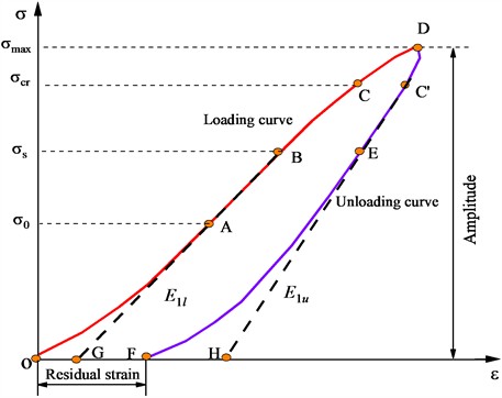
Fig. 2Schematic diagram of the constitutive model

(1) When , only the crack element is active, and the corresponding constitutive model is defined as follows:
For a specimen height of 100 mm, the following equation can be derived:
where and are model parameters for the crack element in the loading segment; and are the stress and strain of the crack element; is the crack width; and is the specimen height. The values of and can be determined from the endpoint of the compaction segment (point A), where the tangent slope equals the elastic modulus . Assuming continuity and differentiability at point A gives:
The values of and can be determined from Eq. (3-4):
where is the loading elastic modulus, and and are the stress and strain at the endpoint of the compaction segment, respectively.
(2) When , the elastic element becomes active, and the stress acting on this element is expressed as follows:
The segment AB is determined using Hooke’s law:
Thus, we obtain:
The total strain can be expressed as follows:
where is the closure stress of the crack element, which is equal to the stress at point A; and are the stress and strain of the elastic element, respectively; and is the total strain.
(3) When (i.e., segment BC), the stress-strain response is nonlinear and the viscoelastic element is activated. According to the element-combination rules, the stress acting on this element is:
The strain of the viscoelastic element is given by:
The stress-strain relationship defined by the element is given by:
Integrating Eq. (13) yields:
where is the stress at the endpoint of the elastic segment; , , and are the total strain, viscous strain, and elastic strain of the viscoelastic element, respectively; , and are the stress rate, total strain rate, and viscous strain rate of the viscoelastic element, respectively; and are the loading rate and the viscosity coefficient of the viscoelastic element; and are the loading duration and the corresponding time at the endpoint of the elastic segment, respectively; is the elastic modulus of the viscoelastic element.
(4) When (i.e., segment CDC'), the viscoplastic element is activated. Following Ref. [39], its constitutive equation is:
Under constant stress, Eq. (15) has the following solution:
The model parameters are obtained from the following integral formulation (see Fig. 3).
Fig. 3Schematic of the integration procedure for the viscoplastic segment
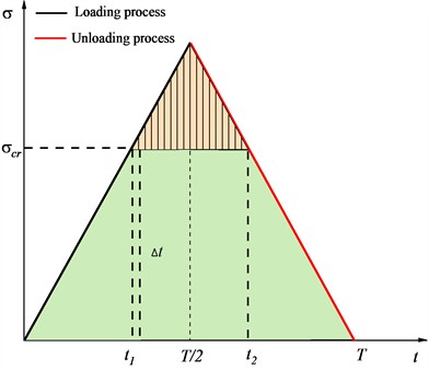
Let the fatigue stress threshold correspond to time points and . The curve segment during the time period - is divided into several constant-stress intervals spaced by , within which creep occurs. Summing these intervals yields the viscoplastic strain over one cycle:
If the cyclic loading follows a triangular waveform, the in segments (,) and (,) should be represented by piecewise functions as follows:
The first term on the right-hand side is:
The second term on the right-hand side is:
Adding these terms gives the viscoplastic strain:
where , , and denote the total viscoplastic strain and the viscoplastic strains generated during loading and unloading, respectively; is the fatigue stress threshold; and are the loading and unloading durations associated with the threshold , respectively; is the duration of one loading-unloading cycle; is the viscoplastic coefficient; and is a model parameter.
(5) C’E segment.
This segment represents elastic unloading and is governed by Hooke’s law:
where is the stress at the endpoint of the unloading elastic segment; is the elastic strain generated when the unloading stress is ; is the unloading stiffness. is the strain at the endpoint of the unloading elastic segment, which is determined by Eq. (24).
(6) EF segment.
This segment represents the crack opening segment during the unloading process and can be considered the reverse process of crack closure. Therefore, its constitutive relationship is also determined by the crack element, which is expressed as follows:
This allows us to calculate the strain at the crack opening point E:
where represents the strain corresponding to stress during the crack opening process; denotes the accumulated plastic strain after complete unloading; and are model parameters, whose values can be determined from the characteristic point E. The determination method is identical to that used for the compression segment during loading and is therefore not elaborated further.
The total strain over the complete cycle is:
3. Model validation
3.1. Experimental procedure
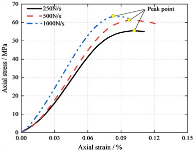
The experimental setup is shown in Fig. 4. A TFD-2000/D dynamic-disturbance triaxial testing system was used for loading, and a DS5-16B full-information acoustic-emission system was used to monitor the specimens in real time throughout cyclic loading and unloading. The AE measurements were used to examine time-dependent behavior during unloading. Fine-grained marble from Guangxi was prepared as cylindrical specimens 50 mm in diameter and 100 mm in height. The flatness of the end surfaces was controlled within 0.05 mm. The P-wave velocity of each specimen was then measured, and specimens with similar wave velocities were selected for testing. Because peak strength depends on loading rate and fatigue failure depends strongly on stress level, the same upper stress ratio was used for all tests to minimize stress-level effects [8]. Cyclic loading was applied under stress control using a triangular waveform. The lower stress was 0.5 MPa, and the upper stress was set to 90 % of the peak stress. Three loading rates (250, 500, and 1000 N/s) were used to investigate time effects. Before the cyclic tests, uniaxial compression tests were conducted at each loading rate to determine the corresponding peak stress and hence the upper stress limit for cyclic loading (Fig. 5).
Fig. 4Test equipment and rock samples. The photos were taken by the authors on 10.08.2025, at Huaqiao University in the city of Xiamen
a) Loading system
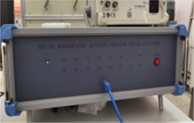
b) AE system

c) Rock samples
The uniaxial compression tests yielded peak stresses of 55, 61, and 63 MPa at loading rates of 250, 500, and 1000 N/s, respectively. The corresponding peak strains were 0.101 %, 0.0976 %, and 0.0823 %. Thus, peak stress increased with loading rate, whereas peak strain decreased. The upper stress for the cyclic loading-unloading tests were therefore set to 50, 55, and 57 MPa, respectively.
Fig. 5Uniaxial compression test result
3.2. Experimental results
3.2.1. Stress-strain behavior
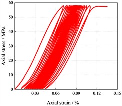
Fig. 6 presents the cyclic loading-unloading stress-strain curves at loading rates of 250, 500, and 1000 N/s. The specimens failed after 5, 9, and 22 cycles, respectively, in each case after reaching the upper stress during the final loading stage. Thus, at the same upper stress ratio, fatigue life increased with loading rate. At 1000 N/s, the stress-strain curve exhibited a sparse-dense-sparse pattern. As the loading rate increased, the hysteresis loops evolved from relatively full to more elongated shapes, reflecting a reduction in plastic strain. Lower loading rates allowed more time for creep deformation during each cycle and consequently produced greater plastic deformation. During unloading, the axial strain decreased slowly or even continued to increase because of time-dependent deformation [38]. These results demonstrate that time effects become more pronounced as the loading rate decreases.
Fig. 6Cyclic loading-unloading stress-strain curves
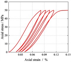
a) 250 N/s
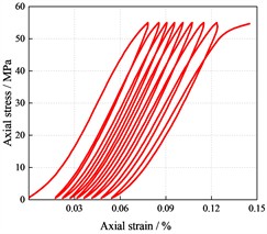
b) 500 N/s
c) 1000 N/s
3.2.2. Acoustic emission response
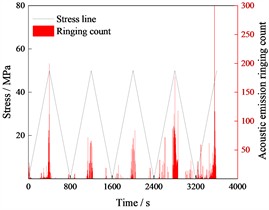
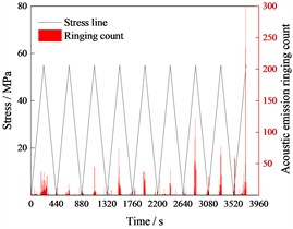
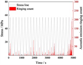
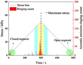
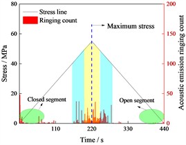
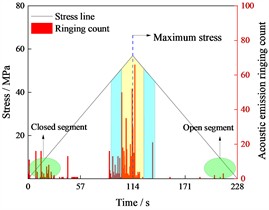
Previous constitutive studies of rock under cyclic loading have often neglected time effects during unloading. Acoustic emission monitoring was therefore conducted throughout cyclic loading-unloading, and the results are shown in Figs. 7-8. For clarity, the AE signals from the first cycle at each loading rate are highlighted. Overall, AE activity was concentrated primarily near the upper stress of each cycle. During the final cycle, AE events occurred continuously as the load increased, indicating that the rock was approaching failure and losing its load-bearing capacity.
Detailed analysis of the first cycle revealed AE activity during both loading and early unloading, consistent with Refs. [40] and [41]. The duration of AE activity during unloading generally decreased as the loading rate increased. Acoustic emission is governed not only by the applied load but also by frictional sliding along microcracks [42]. Once the load exceeds a damage threshold, internal cracks continue to initiate and propagate, and this time-dependent damage can persist briefly even after unloading begins. This mechanism is analogous to delayed deformation during creep and explains why time effects must be considered during early unloading. The experiments further showed that damage and plastic strain accumulated during unloading, accounting for the continued increase in axial strain during its early stage. Differences in fatigue life among the loading rates can therefore be attributed partly to differences in the duration of the viscoplastic loading-unloading segments and the resulting creep-induced plastic deformation. AE events were also detected at the beginning of loading and near the end of unloading. Because AE activity reflects internal crack evolution, these events indicate that cracks continued to close or reopen even at relatively low stress levels.
Fig. 7Acoustic emission results of all cyclic progress
a) 250 N/s
b) 500 N/s
c) 1000 N/s
Fig. 8Acoustic emission test results of 1st cyclic progress
a) 250 N/s
b) 500 N/s
c) 1000 N/s
3.3. Theoretical verification
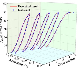
The model parameters were determined based on the developed constitutive model equations and the data from cyclic loading-unloading tests at varying rates through a combination of eigenvalue analyses and fitting methods. Parameter identification was performed using 1stOpt software, which has strong self-adaptability in fitting, the algorithm employs the Levenberg-Marquardt method, with a convergence criterion of 1.0E-12. This process generated theoretical stress-strain curves for cyclic loading-unloading tests. The verification results are presented in Fig. 9.
Fig. 9 illustrates that the theoretical stress-strain results derived from the proposed model, which incorporates time effects, closely match the test results. The model thoroughly accounts for variations in the rock’s internal structure during loading-unloading, as well as creep strain induced by load duration during unloading. This led to a closer alignment between the theoretical and experimental stress-strain curves. The correlation coefficient between theoretical and test results at all three loading rates is close to 1. As the loading rate increases, the maximum error rates at the peak stress are 1.5 %, 0.35 %, and 0.6 % respectively, and these occur on the 2nd, 2nd, and 20th cycles of loading-unloading. The proposed formulation therefore reduces the error introduced when unloading duration is neglected and provides a more physically grounded description than a purely curve-fitted unloading relationship.
Fig. 9Comparison of theoretical and experimental stress-strain curves
a) 250 N/s
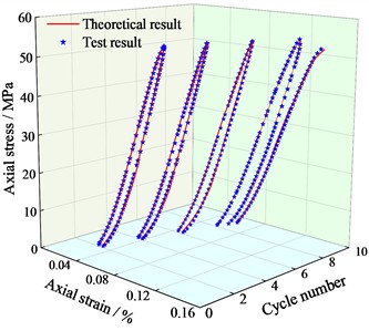
b) 500 N/s
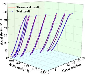
c) 1000 N/s
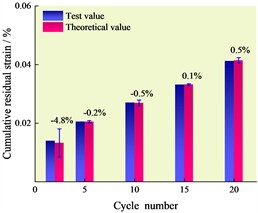
The model also accounts for time effects during loading-unloading and can therefore predict the plastic strain accumulated during unloading. Fig. 10 compares the cumulative plastic strain increment predicted for each cycle with the measured cumulative plastic strain after unloading. The predicted and test values agreed closely. The maximum error, approximately 6 %, occurred at 250 N/s, whereas the errors for the other test conditions were below 5 %. At 250 N/s, the longer unloading duration produced greater viscoelastic strain recovery and a smaller plastic strain, thereby increasing the discrepancy between the predicted and test values.
Fig. 10Comparison of predicted and measured plastic strains
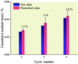
a) 250 N/s
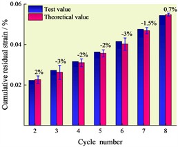
b) 500 N/s
c) 1000 N/s
3.4. Validation using published experimental data
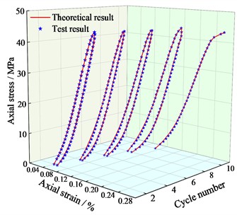
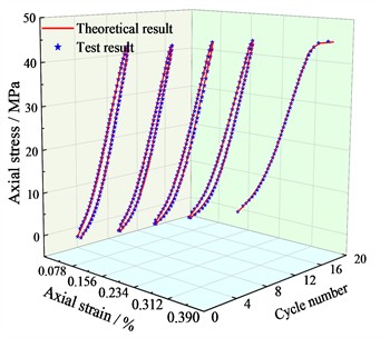
Experimental data from Refs. [24, 43] were utilized to validate the proposed model. The results are presented in Fig. 11. The validation results indicated a strong correlation between the referenced experimental data and the theoretical results from this study, with correlation coefficients exceeding 0.95. The maximum errors at the peak stress of Refs. [24, 43] were 0.75 % and 3.17 % respectively, and they occurred in the 4th and 19th loading-unloading, respectively. These findings demonstrate the broad applicability and accuracy of the proposed model.
Fig. 11Validation against published experimental data
a) Reference [24]
b) Reference [43]
4. Evolution of model parameters
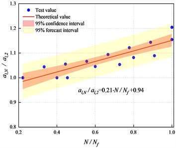
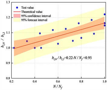
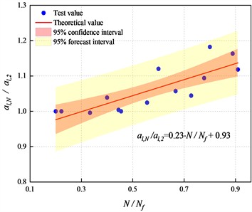
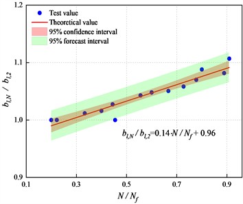
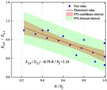
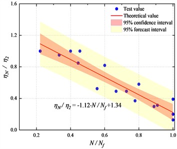
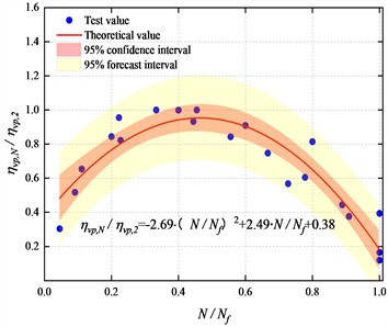
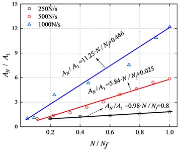
This section examines the evolution of the constitutive-model parameters with cycle number. Because the three loading rates produced substantially different fatigue lives, the raw data could not be compared clearly on a single plot. Both cycle number and model parameters were therefore normalized. To reduce the influence of initial structural variability in the first cycle, the second cycle was used as the normalization baseline. Fig. 12 shows the relationships between the normalized parameters and normalized cycle number.
Fig. 12 indicated that, under cyclic loading-unloading conditions, the normalized values of all model parameters fell within the 95 % confidence interval (except for parameter ). Except for the viscoplastic coefficient, all other parameters exhibited a linear relationship with the increasing number of cycles. While the normalized value of parameter fell outside the 95 % confidence interval.
Fig. 12Evolution of model parameters
a)
b)
c)
d)
e)
f)
g)
h)
As indicated by Eq. (16), parameter predominantly governs the initial viscoplastic strain of the rock under a single loading-unloading cycle. Its influence on viscoplastic strain diminishes progressively with time. During the entire cyclic loading-unloading process, a higher loading rate intensifies the temporal evolution of parameter ; moreover, its value increases monotonically with the number of cycles. This trend suggests that, as the rock’s mechanical properties degrade, the time-dependent nature of its viscoplastic strain becomes increasingly pronounced.
5. Conclusions
This study developed and experimentally validated a constitutive model for rock subjected to cyclic loading-unloading. The principal conclusions are as follows:
1) At the same upper stress ratio, fatigue life depended strongly on loading rate. Lower loading rates produced fewer cycles to failure and more pronounced time-dependent deformation.
2) During loading, AE events occurred in clusters and were concentrated mainly near the upper stress. AE activity was also detected during early unloading, and its duration increased as the unloading rate decreased.
3) The stress-strain curves predicted by the proposed time-dependent model agreed closely with the test results, as did the predicted and measured plastic strains. All model parameters varied approximately linearly with cycle number except the viscoplastic coefficient, which followed a quadratic trend. Overall, the parameters exhibited clear and physically consistent evolutionary patterns.
References
-
Z. Song, J. Zhang, Y. Zhang, X. Dong, and S. Wang, “Characterization and evaluation of brittleness of deep bedded sandstone from the perspective of the whole life-cycle evolution process,” International Journal of Mining Science and Technology, Vol. 33, No. 4, pp. 481–502, Mar. 2023, https://doi.org/10.1016/j.ijmst.2022.12.007
-
Z. Song and J. Zhang, “Research on the progressive failure process and fracture mechanism of rocks with the structural evolution perspective,” Journal of Structural Geology, Vol. 154, p. 104484, Nov. 2021, https://doi.org/10.1016/j.jsg.2021.104484
-
Z. Yang, J. Fan, J. Chen, D. Jiang, J. Suo, and Z. Li, “Dilatancy and acoustic emission characteristics of rock salt in variable-frequency fatigue tests,” Rock Mechanics and Rock Engineering, Vol. 57, No. 12, pp. 10877–10894, Aug. 2024, https://doi.org/10.1007/s00603-024-04119-7
-
B. Liang, D. Wang, H.-J. Luan, L. Dong, J.-K. Liu, and C.-S. Wang, “Dynamic response characteristics of muddy sandstone in pumped storage mine under action of high-stress dynamic disturbance,” Journal of Central South University, Vol. 31, No. 8, pp. 2736–2747, Oct. 2024, https://doi.org/10.1007/s11771-024-5728-y
-
B.-G. He, H.-Y. Zhang, X.-T. Feng, and X.-R. Meng, “Time-delayed rockbursts induced by dynamic disturbances: 793 cases in deep tunnels,” Rock Mechanics and Rock Engineering, Vol. 58, No. 7, pp. 8047–8070, 2025, https://doi.org/10.1007/s00603-025-04491-y
-
H. Xie et al., “Fatigue fracture behaviors and damage evolution of coal samples treated with drying-wetting cycles investigated by acoustic emission and nuclear magnetic resonance,” International Journal of Rock Mechanics and Mining Sciences, Vol. 185, p. 105976, 2024, https://doi.org/10.1016/j.ijrmms.2024.105976
-
Y. Liu and F. Dai, “A review of experimental and theoretical research on the deformation and failure behavior of rocks subjected to cyclic loading,” Journal of Rock Mechanics and Geotechnical Engineering, Vol. 13, No. 5, pp. 1203–1230, May 2021, https://doi.org/10.1016/j.jrmge.2021.03.012
-
B. Sun, Z. Zhu, C. Shi, and Z. Luo, “Dynamic mechanical behavior and fatigue damage evolution of sandstone under cyclic loading,” International Journal of Rock Mechanics and Mining Sciences, Vol. 94, pp. 82–89, Mar. 2017, https://doi.org/10.1016/j.ijrmms.2017.03.003
-
M. N. Bagde and V. Petroš, “Fatigue and dynamic energy behaviour of rock subjected to cyclical loading,” International Journal of Rock Mechanics and Mining Sciences, Vol. 46, No. 1, pp. 200–209, Jun. 2008, https://doi.org/10.1016/j.ijrmms.2008.05.002
-
Q. Zhang et al., “Damage evolution and acoustic emission characteristics of sandstone under different true triaxial cyclic loading and unloading modes,” Engineering Failure Analysis, Vol. 167, p. 108947, Oct. 2024, https://doi.org/10.1016/j.engfailanal.2024.108947
-
Y. Wang, L. Ma, P. Fan, and Y. Chen, “A fatigue damage model for rock salt considering the effects of loading frequency and amplitude,” International Journal of Mining Science and Technology, Vol. 26, No. 5, pp. 955–958, Jun. 2016, https://doi.org/10.1016/j.ijmst.2016.05.054
-
J. Zhang, R. Du, Y. Chen, and Z. Huang, “Experimental investigation of the mechanical properties and energy evolution of layered phyllite under uniaxial multilevel cyclic loading,” Rock Mechanics and Rock Engineering, Vol. 56, No. 6, pp. 4153–4168, Mar. 2023, https://doi.org/10.1007/s00603-023-03279-2
-
Y. Wang, P. Tang, P. Li, and Y. Xia, “Effect of disturbed frequency on rock failure and energy characteristics exposed to triaxial fatigue and multistage unloading confining pressure (TF-MSUCP) conditions,” Engineering Failure Analysis, Vol. 145, p. 106997, Dec. 2022, https://doi.org/10.1016/j.engfailanal.2022.106997
-
Y. Liu, F. Dai, P. Fan, N. Xu, and L. Dong, “Experimental investigation on the influence of joint geometric configurations on the mechanical properties of intermittent jointed rock models under cyclic uniaxial compression,” Rock Mechanics and Rock Engineering, Vol. 50, No. 6, pp. 1453–1471, 2017, https://doi.org/10.1007/s00603-017-1190-6
-
C. Li, C. Gao, H. Xie, and N. Li, “Experimental investigation of anisotropic fatigue characteristics of shale under uniaxial cyclic loading,” International Journal of Rock Mechanics and Mining Sciences, Vol. 130, p. 104314, Apr. 2020, https://doi.org/10.1016/j.ijrmms.2020.104314
-
Y. Liu, F. Dai, P. Feng, and N.-W. Xu, “Mechanical behavior of intermittent jointed rocks under random cyclic compression with different loading parameters,” Soil Dynamics and Earthquake Engineering, Vol. 113, pp. 12–24, Jun. 2018, https://doi.org/10.1016/j.soildyn.2018.05.030
-
K. Peng, J. Zhou, Q. Zou, J. Zhang, and F. Wu, “Effects of stress lower limit during cyclic loading and unloading on deformation characteristics of sandstones,” Construction and Building Materials, Vol. 217, pp. 202–215, May 2019, https://doi.org/10.1016/j.conbuildmat.2019.04.183
-
S.-Q. Yang, W.-L. Tian, and P. G. Ranjith, “Experimental investigation on deformation failure characteristics of crystalline marble under triaxial cyclic loading,” Rock Mechanics and Rock Engineering, Vol. 50, No. 11, pp. 2871–2889, Jul. 2017, https://doi.org/10.1007/s00603-017-1262-7
-
J.-Q. Xiao, D.-X. Ding, F.-L. Jiang, and G. Xu, “Fatigue damage variable and evolution of rock subjected to cyclic loading,” International Journal of Rock Mechanics and Mining Sciences, Vol. 47, No. 3, pp. 461–468, Feb. 2010, https://doi.org/10.1016/j.ijrmms.2009.11.003
-
J.-Q. Xiao, D.-X. Ding, G. Xu, and F.-L. Jiang, “Inverted S-shaped model for nonlinear fatigue damage of rock,” International Journal of Rock Mechanics and Mining Sciences, Vol. 46, No. 3, pp. 643–648, Dec. 2008, https://doi.org/10.1016/j.ijrmms.2008.11.002
-
Y. Zhu, J. Yu, Y. Cai, X. Tang, W. Yao, and X. Liu, “A novel fatigue damage model of rock considering temperature effects,” Advances in Civil Engineering, Vol. 2020, No. 1, pp. 1–11, Jul. 2020, https://doi.org/10.1155/2020/8838335
-
Q. He et al., “Fatigue properties and constitutive model of Jintan salt rock subjected to complex cyclic loading,” International Journal of Mining Science and Technology, Vol. 35, No. 1, pp. 121–133, Jan. 2025, https://doi.org/10.1016/j.ijmst.2024.12.007
-
Y. Zhu, Y. Cai, Q. Huang, C. Ren, Y. Zhang, and J. Yu, “Mechanical properties and constitutive model of deep marble under alternating creep-fatigue action,” Engineering Fracture Mechanics, Vol. 312, p. 110611, Nov. 2024, https://doi.org/10.1016/j.engfracmech.2024.110611
-
C. Ren, J. Yu, X. Liu, Z. Zhang, and Y. Cai, “Cyclic constitutive equations of rock with coupled damage induced by compaction and cracking,” International Journal of Mining Science and Technology, Vol. 32, No. 5, pp. 1153–1165, Jul. 2022, https://doi.org/10.1016/j.ijmst.2022.06.010
-
J. Wang, Q. Zhang, X. Liu, Z. Song, and S. Feng, “Creep properties and constitutive model for salt rock subjected to uniaxial trapezoidal cyclic loading,” Journal of Energy Storage, Vol. 52, p. 105023, Jun. 2022, https://doi.org/10.1016/j.est.2022.105023
-
X. Wang, L. Song, C. Xia, G. Han, and Z. Zhu, “Nonlinear elasto-visco-plastic creep behavior and new creep damage model of dolomitic limestone subjected to cyclic incremental loading and unloading,” Sustainability, Vol. 13, No. 22, p. 12376, Nov. 2021, https://doi.org/10.3390/su132212376
-
B. Zeb et al., “Visual intelligence for automated fall sensing: a systematic review of architectures, datasets, and evaluation gaps,” ICCK Transactions on Sensing, Communication, and Control, Vol. 3, No. 2, pp. 90–108, Jun. 2026, https://doi.org/10.62762/tscc.2026.604481
-
R. Ji, X. Zhang, X. Tang, X. Wang, Y. Xu, and J. Shi, “Road crack segmentation algorithm based on multiple attention fusion and defect correction,” ICCK Transactions on Intelligent Systematics, Vol. 3, No. 2, pp. 126–144, Jun. 2026, https://doi.org/10.62762/tis.2025.325163
-
F. Ali, M. Ali, and Z. Muhammad, “MAFNet: multi-level attention fusion network for precise prominence analysis in visual sensing systems,” ICCK Transactions on Sensing, Communication, and Control, Vol. 3, No. 2, pp. 124–138, Jun. 2026, https://doi.org/10.62762/tscc.2025.390515
-
I. M. Khan and W. Khan, “Scale-specific visual sensing for colonoscopy polyp segmentation via hybrid CNN-transformer attention,” ICCK Transactions on Sensing, Communication, and Control, Vol. 3, No. 2, pp. 109–123, Jun. 2026, https://doi.org/10.62762/tscc.2026.664028
-
Y. Lin, “Pairwise Frank-Wolfe for maximum inscribed balls: enabling real-time geometric optimization,” ICCK Transactions on Advanced Computing and Systems, Vol. 2, No. 1, pp. 61–73, Jan. 2026, https://doi.org/10.62762/tacs.2025.318429
-
Y. Liu and F. Dai, “A damage constitutive model for intermittent jointed rocks under cyclic uniaxial compression,” International Journal of Rock Mechanics and Mining Sciences, Vol. 103, pp. 289–301, Feb. 2018, https://doi.org/10.1016/j.ijrmms.2018.01.046
-
E. C. David, N. Brantut, A. Schubnel, and R. W. Zimmerman, “Sliding crack model for nonlinearity and hysteresis in the uniaxial stress-strain curve of rock,” International Journal of Rock Mechanics and Mining Sciences, Vol. 52, pp. 9–17, 2012, https://doi.org/10.1016/j.ijrmms.2012.02.001
-
S.-W. Zhou, C.-C. Xia, H.-B. Zhao, S.-H. Mei, and Y. Zhou, “Statistical damage constitutive model for rocks subjected to cyclic stress and cyclic temperature,” Acta Geophysica, Vol. 65, No. 5, pp. 893–906, Aug. 2017, https://doi.org/10.1007/s11600-017-0073-2
-
Q. Lin, P. Cao, S. Mao, C. Ou, and R. Cao, “Fatigue behaviour and constitutive model of yellow sandstone containing pre-existing surface crack under uniaxial cyclic loading,” Theoretical and Applied Fracture Mechanics, Vol. 109, p. 102776, Sep. 2020, https://doi.org/10.1016/j.tafmec.2020.102776
-
T. Li, X. Pei, D. Wang, R. Huang, and H. Tang, “Nonlinear behavior and damage model for fractured rock under cyclic loading based on energy dissipation principle,” Engineering Fracture Mechanics, Vol. 206, pp. 330–341, Dec. 2018, https://doi.org/10.1016/j.engfracmech.2018.12.010
-
D.-F. Yang et al., “Experiment and study on mechanical property of sandstone post-peak under the cyclic loading and unloading,” Geotech Geol Eng, Vol. 36, pp. 1609–1620, 2018, https://doi.org/10.1007/s10706-017-0414-6
-
J. Wang, Q. Zhang, Z. Song, and Y. Zhang, “Experimental study on creep properties of salt rock under long-period cyclic loading,” International Journal of Fatigue, Vol. 143, No. 9, p. 106009, Oct. 2020, https://doi.org/10.1016/j.ijfatigue.2020.106009
-
Y. Ye and H.-K. Chen, “Different modes of viscoplastic deformation behavior for asphalt mixtures,” (in Chinese), Journal of Chongqing Jiaotong University (Nature Science), Vol. 33, No. 3, pp. 45–48, 2014.
-
Z. Wang, J. Yao, N. Tian, J. Zheng, and P. Gao, “Mechanical behavior and damage evolution for granite subjected to cyclic loading,” Advances in Materials Science and Engineering, Vol. 2018, No. 1, pp. 1–10, May 2018, https://doi.org/10.1155/2018/4312494
-
L. Dexing, W. Enyuan, K. Xiangguo, J. Haishan, W. Dongming, and A. Muhammad, “Damage precursor of construction rocks under uniaxial cyclic loading tests analyzed by acoustic emission,” Construction and Building Materials, Vol. 206, pp. 169–178, Feb. 2019, https://doi.org/10.1016/j.conbuildmat.2019.02.074
-
Q. Meng, M. Zhang, L. Han, H. Pu, and T. Nie, “Effects of acoustic emission and energy evolution of rock specimens under the uniaxial cyclic loading and unloading compression,” Rock Mechanics and Rock Engineering, Vol. 49, No. 10, pp. 3873–3886, Aug. 2016, https://doi.org/10.1007/s00603-016-1077-y
-
X. Tang et al., “Equivalent fatigue stress and non-linear constitutive model for fatigue of rock,” (in Chinese), Chinese Journal of Geotechnical Engineering, Vol. 43, No. 1, pp. 102–111, 2021.
About this article

This study was financially supported by the National Natural Science Foundation of China (Grants No. 52374090, 52278351), the Industry-university-research Cooperation Project in Fujian Province, China (2025H6010), the Natural Science Foundation of Fujian Province (No. 2023J011105), the Guizhou Provincial Basic Research Program (Natural Science) Youth Guidance Project (Qianke Foundation-QN [2025]192).
The datasets generated during and/or analyzed during the current study are available from the corresponding author on reasonable request.
Yaoliang Zhu: data curation, formal analysis, methodology, experiment. Yanyan Cai: supervision. Chonghong Ren: experiment, methodology. Qinzheng Huang: Data curation. Jin Yu: Conceptualization.
The authors declare that they have no conflict of interest.

