Abstract
A coupled electromechanical model is developed for a previously reported suspended double-mass vibratory lapping-polishing machine driven by six sequentially activated solenoids. The model combines the planar motion of the lap and carrier, elastic and dissipative forces, regularized dry-viscous contact friction, solenoid current transients, displacement-dependent inductance, and electromagnetic-force generation. Simulations were performed for excitation frequencies of 3-35 Hz and supply voltages of 8, 10, and 12 V. At 12 V and 8.5 Hz, the predicted relative trajectory radius is 0.217 mm, the peak current and electromagnetic force reach 1.89 A and 3.66 N, and the mean contact-dissipation power equals 23 mW. For the adopted solenoid parameters and switching law, the coupled model, unlike the prescribed-force benchmark, exhibits no pronounced resonance near the mechanical natural frequency because the shortened voltage pulses limit current build-up at high frequencies. The contact-power maxima occur at 5, 7, and 8.5 Hz for 8, 10, and 12 V, respectively. The results demonstrate that favorable operating regimes predicted by the model must be selected using coupled dynamic and energy criteria.
Highlights
- A coupled model links six solenoid current transients and gap-dependent inductances to planar double-mass motion and separate electrical, structural and contact losses.
- At 12 V and 8.5 Hz, simulations predict a 0.217 mm relative trajectory radius, 1.89 A peak current and 3.66 N peak solenoid force.
- For the adopted parameters and switching law, finite current build-up suppresses the pronounced resonance predicted by the prescribed-force model.
- Predicted contact-dissipation power peaks at 5, 7 and 8.5 Hz for 8, 10 and 12 V, reaching 1.90, 11.40 and 23.01 mW, respectively.
- At 12 V and 8.5 Hz, predicted mean electrical input is 16.22 W and the electromechanical power-transfer ratio is 0.144%, with winding losses dominating.
1. Introduction
Lapping and polishing are widely used for obtaining low surface roughness and high dimensional accuracy. Existing studies have addressed the dynamics, working-medium kinematics, and contact interaction of vibratory finishing systems [1]-[5], whereas solenoid-actuator models demonstrate that the generated force is governed by current transients and displacement-dependent inductance [6], [7]. Previous investigations developed a suspended double-mass lapping machine and its six-channel sequential control system [8]-[11], while the technological relevance of vibration amplitude and frequency was confirmed in [12].
The present work continues the authors’ research on suspended double-mass lapping machines [8]-[12]. The progression of that research defines the scope of the present contribution. Study [8] established a mechanical model with prescribed harmonic excitation and experimentally identified equivalent damping. Study [9] investigated planar motion using analytical modeling, SolidWorks simulation, and prototype tests. Study [10] addressed a two-solenoid configuration producing controlled translational oscillations. The six-channel controller and experimental effects of excitation frequency and voltage on circular motion were reported in [11], while [12] examined the influence of lapping parameters on surface roughness. A further conference publication [13] documented the implementation and experimental testing of the six-solenoid sequential controller. Thus, the machine architecture, circular-motion principle, and sequential voltage-control law are established results.
The mechanical models in [8]-[10] use prescribed excitation forces and equivalent damping without resolving all six winding currents and the electrical-to-contact power flow. Consequently, they do not determine how the imposed voltage pulses generate forces or how winding, structural, and contact losses vary together. The controller studies [11], [13] establish the practical feasibility of the actuation sequence but do not provide this coupled dynamic and energy calculation. The solenoid relations in [6], [7] are established modeling tools; the contribution here is their integration and application to this machine.
The purpose of this study is to quantify the dynamic and energy characteristics of the previously developed machine. Its specific contribution is a coupled formulation linking six solenoid current states and displacement-dependent inductances to planar double-mass motion, with separate evaluation of electrical input, copper losses, structural dissipation, and contact dissipation. The numerical frequency and voltage sweeps then relate finite current build-up to force attenuation, the frequency response, and the operating frequencies associated with maximum contact-dissipation power. These results extend the earlier mechanical and control studies without claiming a new mechanism or switching algorithm.
2. Machine design and coupled model
Fig. 1 represents the previously developed machine concept [9], [11], [13] and defines the geometry and notation used in the present model. The six-solenoid layout and sequential actuation principle are retained from those studies; the extension concerns the coupled electrical states and the explicit power components in Eqs. (1)-(4). The oscillatory system consists of an upper lapping-polishing plate of mass and a suspended lower carrier-workpiece assembly of mass , interconnected by six identical radial spring-loaded solenoids arranged at , 1,…, 6 (Fig. 1). The solenoid bodies are hinge-mounted on the carrier, whereas their rods are connected to the upper lap. Sequential activation with a delay produces a rotating internal excitation and antiphase planar motion of the two masses. Both members are treated as rigid bodies; vertical motion, rotation about the vertical axis, and the horizontal compliance of the long suspension ropes are neglected. Their generalized-coordinate vector is .
Fig. 1Calculation diagram of the vibratory machine’s oscillatory system
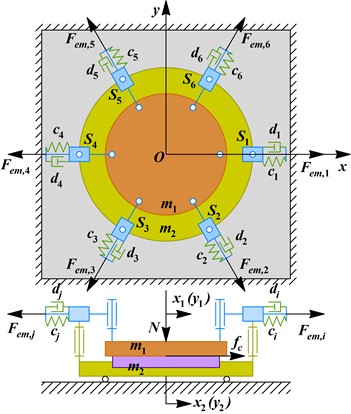
For the -th solenoid unit, the unit vector directed along its actuation axis and the corresponding generalized-force direction are introduced as , . The relative deformation and relative velocity of the -th spring-solenoid unit are , . The planar motion of the double-mass oscillatory system is described by:
where is the mass matrix; and are the stiffness and structural-damping coefficients of the -th spring-loaded actuator. Unlike the previously used model [9], Eq. (1) does not prescribe three ideal harmonic forces. Instead, the instantaneous forces are obtained from the electrical states and armature positions of all six solenoids.
The relative velocity in the lapping contact is and . The friction force acting on the upper lap is represented by a regularized dry-viscous law:
where is the prescribed normal preload, is the viscous contact-damping coefficient, is the constant dry-friction coefficient, and is a small regularization parameter preventing numerical discontinuities at zero velocity.
The effective magnetic gap of the -th solenoid is expressed as , where is its initial value. The -th electrical circuit, electromagnetic force, and sequential voltage command are described jointly by:
where , , , and denote the terminal voltage, winding current, electrical resistance, and position-dependent inductance, respectively. The symbol in Eq. (3) denotes a periodic unit-amplitude rectangular pulse of duration . Thus, successive commands are delayed by , corresponding to a phase shift of 60°.
The principal instantaneous power components and the cycle-averaged electromechanical power-transfer ratio are:
where is the electrical input power, represents the winding losses, is the structural dissipation, is the power dissipated in the technological contact, and is the cycle-averaged electromechanical power-transfer ratio.
3. Model parameters and simulation conditions
The mechanical parameters were adopted from the compact six-solenoid machine considered in [9]-[11] (see Table 1). The upper-lap mass was 0.42 kg, whereas 1.25 kg included the carrier, fixtures, and workpiece. Each radial spring had 3700 N/m. Consequently, the equivalent directional stiffness, reduced mass, and undamped natural frequency were 11.1 kN/m, 0.314 kg, and 29.9 Hz, respectively. Structural losses were introduced through 0.02, giving a total directional damping of 2.36 N·s/m and 0.79 N·s/m for each actuator. The contact model used 20 N·s/m, 0.10, and 10-4m/s. For a circular treated area of diameter 48 mm, 1.81×10⁻³ m2. At 8.75 kPa [12], the constant externally prescribed preload was 15.8 N.
Identical solenoids were represented by 6 Ω and 10 mm. Because the available publications do not provide a force-current-gap map, the position-dependent inductance was calibrated numerically as:
The constants were 10 mH, 4.5×10⁻⁴ H·m, and 5 mm; hence 40 mH and the nominal electrical time constant was 6.7 ms. At 12 V and , the quasi-steady current was 2 A and the calculated electromagnetic force was 4 N, equal to the force amplitude used in the preceding simplified model [9]. The catalogue force of 65 N was treated only as an upper actuator constraint [11].
One solenoid received a nonzero voltage command at a time; the commands (pulses) did not overlap, and the switches were ideal. Driver and converter losses, magnetic saturation and hysteresis, mutual inductance, and thermal variation of the winding resistance were neglected. The resulting fourteen first-order differential equations were integrated using a custom fixed-step fourth-order Runge-Kutta scheme. Zero initial displacements, velocities, and currents were imposed. Each condition was simulated over 60 excitation periods using 960 steps per period for time histories and 1920 steps per period for frequency sweeps; the first 40 periods were discarded, and the final 20 periods were analyzed. Frequency sweeps were performed from 3 to 35 Hz with a step of 0.5 Hz at supply voltages of 8, 10, and 12 V.
Table 1Adopted model parameters and varied control inputs
Group | Parameters and values | Status |
Mechanical | 0.42 kg; 1.25 kg; 3700 N/m; 0.02; 0.79 N·s/m; 29.9 Hz | Adopted / calculated |
Contact | Contact damping – 20 N·s/m; 0.10; 10-4m/s; 8.75 kPa; contact area – 1.81×10⁻³ m2; 15.8 N | Adopted |
Solenoid | 6Ω; 10 mm; 10 mH; 4.5×10⁻⁴ H·m; inductance-offset parameter 5 mm; 40 mH | Calibrated |
Control inputs | 8, 10, 12 V; 3,…, 35 Hz; 0.5 Hz; pulse width – ; phase shift 60° | Varied |
4. Results and discussion
The baseline response at 12 V and 8.5 Hz is presented in Fig. 2. A periodic regime was reached after approximately 0.24 s. The upper lap and lower carrier move in antiphase with equivalent trajectory radii of 0.1621 and 0.0545 mm, respectively, whereas the relative trajectory radius is 0.2166 mm. The ratio 0.1621/0.0545 ≈ 2.98 agrees with 2.98, confirming the momentum balance of the internally excited double-mass system. The trajectory is nearly isotropic but exhibits a sixfold radial modulation caused by sequential switching of the solenoids. The solenoid current increased and decayed gradually despite the rectangular voltage pulse; its peak value is 1.89 A and the corresponding electromagnetic force reaches 3.66 N. Thus, the actual actuator force cannot be represented adequately by an ideal rectangular or sinusoidal function.
At this operating point, according to Fig. 3, the mean electrical input power is 16.22 W, of which 16.2 W corresponds to winding losses. The mean contact- and structural-dissipation powers are 23.013 and 0.422 mW, respectively. Thus, approximately 98.2 % of the mechanical energy is dissipated in the technological contact, while the electrical-to-mechanical efficiency is 0.144 %. Fig. 3(a) compares the coupled model with an ideal prescribed rotating force of 4 N. The ideal model predicts a pronounced resonance near 28 Hz, close to the calculated natural frequency of 29.9 Hz. In contrast, the coupled model exhibits no pronounced resonance because increasing frequency shortens the voltage pulse and restricts the current and electromagnetic-force build-up. At 12 V, the relative trajectory radius decreases from 0.273 mm at 3 Hz to 0.094 mm at 15 Hz and 0.00053 mm at 30 Hz. The maximum contact-dissipation powers occur at 5, 7, and 8.5 Hz for supply voltages of 8, 10, and 12 V, respectively, and reach 1.90, 11.40, and 23.01 mW. The corresponding maximum efficiencies are approximately 0.022 %, 0.098 %, and 0.152 %.
Fig. 2Numerical results at Us= 12 V and f= 8.5 Hz
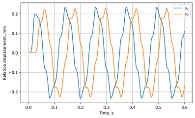
a) Transient relative displacements
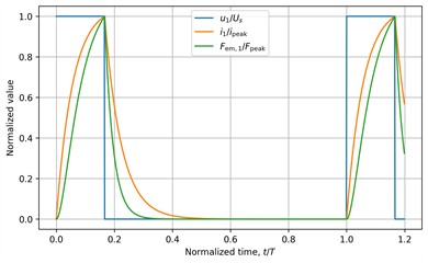
b) Solenoid voltage, current, and force
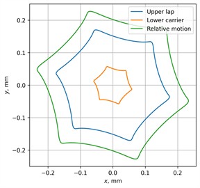
c) Steady-state trajectories of the upper lap, lower carrier, and their relative motion
The main advance relative to [8]-[11] is the explanation of the voltage-to-force-to-motion relationship for the established machine. The nominal electrical time constant is 6.7 ms, whereas the commanded pulse duration decreases from 19.6 ms at 8.5 Hz to 5.6 ms at 30 Hz. Near the mechanical natural frequency, each pulse therefore lasts less than one nominal electrical time constant. The available excitation consequently differs from the frequency-independent force assumed in the benchmark. Together with the adopted contact law, this explains why the mechanical natural frequency alone does not identify the maximum-contact-power regime in the present calculation. The absence of a pronounced resonance peak applies to the adopted parameters and switching law, rather than to all six-solenoid machines.
The energy decomposition also distinguishes electrical consumption from mechanical power dissipated at the contact. Earlier demonstrations of controlled circular trajectories [9], [11], [13] do not establish this power partition. However, contact-dissipation power is a mechanical indicator, not a prediction of material-removal rate or final roughness; the technological dependencies investigated in [12] remain separate. The reported power-transfer ratio includes structural dissipation and should not be interpreted as machining efficiency. Since the inductance law is calibrated to the earlier assumed force level rather than identified from measured force-current-gap data, the calculated amplitudes, powers, and preferred frequencies remain model predictions. The earlier prototype tests provide context for the machine concept, not quantitative validation of the present coupled model. Therefore, the subsequent experimental verification of the presented above modeling results is to be conducted using the existent laboratory equipment available at Lviv Polytechnic National University.
Fig. 3Frequency characteristics of the machine
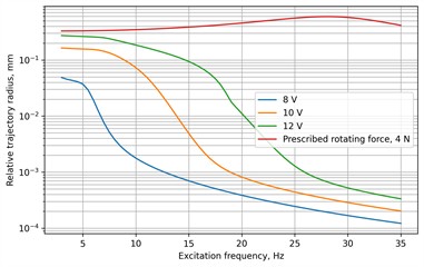
a) Relative trajectory radius (logarithmic scale)
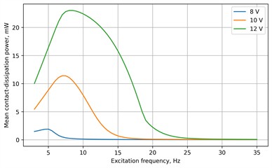
b) Mean contact-dissipation power
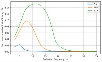
c) Electrical-to-mechanical conversion efficiency
5. Conclusions
For the previously reported six-solenoid double-mass machine, the contribution is a coupled electromechanical and energy analysis extending the earlier mechanical and controller studies [8]-[11], [13]. The proposed model determines the excitation forces from the transient currents and displacement-dependent inductances of the sequentially activated solenoids and separately evaluates the structural, contact, and electrical losses. At the operating conditions 12 V and 8.5 Hz, the upper lap and lower carrier perform antiphase planar oscillations with a relative trajectory radius of 0.2166 mm. The peak solenoid current and electromagnetic force reach 1.887 A and 3.660 N, while the mean contact-dissipation power and electrical-to-mechanical efficiency are 23.013 mW and 0.144 %, respectively.
The ideal prescribed-force model predicts a resonance peak near 28 Hz, whereas no pronounced peak appears in the coupled model for the adopted parameters and switching law because the duration of each voltage pulse decreases with increasing frequency and limits current build-up. The maximum contact-dissipation powers occur at 5, 7, and 8.5 Hz for supply voltages of 8, 10, and 12 V. Therefore, the rational operating frequency cannot be selected from the natural frequency alone and must account for the electrical dynamics of the solenoids and the energy dissipated in the lapping contact. The obtained results should be interpreted as model predictions requiring subsequent experimental verification.
References
-
R. Mediratta, K. Ahluwalia, and S. H. Yeo, “State-of-the-art on vibratory finishing in the aviation industry: an industrial and academic perspective,” The International Journal of Advanced Manufacturing Technology, Vol. 85, No. 1-4, pp. 415–429, Oct. 2015, https://doi.org/10.1007/s00170-015-7942-0
-
F. Hashimoto and S. P. Johnson, “Modeling of vibratory finishing machines,” CIRP Annals, Vol. 64, No. 1, pp. 345–348, Apr. 2015, https://doi.org/10.1016/j.cirp.2015.04.004
-
S. Wan, Y. C. Liu, and K. S. Woon, “A simple general process model for vibratory finishing,” The International Journal of Advanced Manufacturing Technology, Vol. 86, No. 9-12, pp. 2393–2400, Jan. 2016, https://doi.org/10.1007/s00170-016-8379-9
-
Y. B. Tian, Z. W. Zhong, and S. J. Tan, “Kinematic analysis and experimental investigation on vibratory finishing,” The International Journal of Advanced Manufacturing Technology, Vol. 86, No. 9-12, pp. 3113–3121, Feb. 2016, https://doi.org/10.1007/s00170-016-8378-x
-
Y. Hashimoto, T. Sano, T. Furumoto, and A. Hosokawa, “Development an identification method of friction coefficient between wafer and carrier in double-sided lapping,” Precision Engineering, Vol. 56, pp. 364–369, Feb. 2019, https://doi.org/10.1016/j.precisioneng.2019.01.005
-
Z. Peng, L. Chen, L. Wei, W. Gao, Q. Yu, and C. Ai, “Analysis and identification of a dynamic model for proportional solenoid,” IEEE Access, Vol. 9, pp. 92651–92660, Jun. 2021, https://doi.org/10.1109/access.2021.3092142
-
X. Xu, X. Han, Y. Liu, Y. Liu, and Y. Liu, “Modeling and dynamic analysis on the direct operating solenoid valve for improving the performance of the shifting control system,” Applied Sciences, Vol. 7, No. 12, p. 1266, Dec. 2017, https://doi.org/10.3390/app7121266
-
V. Korendiy, V. Zakharov, V. Gurey, P. Dmyterko, I. Novitskyi, and O. Havrylchenko, “Modelling the operation of vibratory machine for single-sided lapping of flat surfaces,” Vibroengineering Procedia, Vol. 38, pp. 1–6, Jun. 2021, https://doi.org/10.21595/vp.2021.22001
-
V. Korendiy, O. Kachur, V. Zakharov, and I. Kuzio, “Studying the dynamics of a vibratory finishing machine providing the single-sided lapping and polishing of flat surfaces,” in Engineering Proceedings, Vol. 24, No. 1, 2022, https://doi.org/10.3390/iecma2022-12898
-
V. Korendiy, O. Kachur, V. Zakharov, I. Kuzio, O. Havrylchenko, and T. Hurey, “Dynamics and control of vibratory finishing machine with translational motion of lapping-polishing plates,” Vibroengineering Procedia, Vol. 44, pp. 8–14, Aug. 2022, https://doi.org/10.21595/vp.2022.22842
-
V. Korendiy, O. Kachur, and V. Zakharov, “Development of a control system for a vibratory lapping-polishing machine,” in 2023 IEEE XXVIII International Seminar/Workshop on Direct and Inverse Problems of Electromagnetic and Acoustic Wave Theory (DIPED), pp. 233–237, 2023, https://doi.org/10.1109/diped59408.2023.10269520
-
V. S. Trush, V. M. Korendiy, O. Y. Kachur, V. M. Zakharov, K. V. Trush, and T. M. Kravchyshyn, “The influence of vibration lapping parameters of flat surfaces on their roughness,” Materials Science, Vol. 60, No. 6, pp. 747–753, Jul. 2025, https://doi.org/10.1007/s11003-025-00945-4
-
O. Kachur, V. Korendiy, V. Zakharov, V. Borovets, O. Havrylchenko, and R. Palash, “Practical implementation and experimental testing of control system for vibratory lapping-polishing machine,” Vibroengineering Procedia, Vol. 50, pp. 8–14, Sep. 2023, https://doi.org/10.21595/vp.2023.23567
About this article

The authors have not disclosed any funding.
The datasets generated during and/or analyzed during the current study are available from the corresponding author on reasonable request.
Prof. Vitaliy Korendiy is a chair of the 78th International Conference on Vibroengineering and was not involved in the editorial review and/or the decision to publish this article.

