Abstract
A hole-drilling method and finite element (FEM) numerical simulation are used to estimate the residual stress of aluminum alloy welding joints. In order to study the influence of hole diameter on measurement accuracy, a group of experiments are conducted. Experiment results show that the measuring error can be the minimal when the drilling hole diameter is 4 mm. Residual stress of 2219-T87 aluminum alloy welding joints under this optimal hole diameter are obtained. The distribution of the residual stress from the welding seam to the outward is first tensile stress and then compressive stress. And the maximum residual stress is 123.2 MPa.
1. Introduction
2219 aluminum alloy has been widely used in aerospace industry due to its satisfactory low-temperature and welding performance as well as its good mechanical properties at the temperature of –250-250°C [1, 2]. In the process of welding, uneven heating of aluminum alloy will always generate strong residual stress at welding joints, leading to the reallocation of stress and strain when bearing, affecting the accuracy of component dimension and position. This will greatly reduce the structural strength of resisting fatigue, stress corrosion and creep cracking, and affect the performances and service life of equipment [3]. Therefore, it's necessary to accurately measure the residual stress of welding structures.
The hole-drilling method for measuring residual stress has been used in engineering practice for years [4]. However, plastic deformation will occur around the hole edge as a result of stress concentration. In accordance with ASTM standards such as E837-81 and E837-85, this method is applied under the condition that residual stress must not be exceeding half of yield strength of a material. In other words, when using this method, the material performances should be still in the elastic state after drilling a hole [5-7]. Thus, when we measure a higher residual stress, the results computed based on the strain-release coefficient determined by state will be greater than the exact value [8].
Theoretically, the smaller the hole diameter is, the more accurate the residual stress will be got, in elastic conditions. However, with a smaller drilling-hole, the released energy will be lessen, as well as a smaller strain release, result in a enlarged relative deviation of measurement [9]. Therefore, looking for an optimal hole diameter to balance the deviation is one of the key issues of residual stress estimation.
Presently, there are several researches on residual stress for welding structures, such as its effects, measurement method, distribution, etc. [10-13].With the rapid development of computer science, numerical simulation becomes an advocated method in engineering analysis. Some researchers like Rodrigues et al. has studied the plastic behavior of high strength steel by numerical method [14].
Considering the research methods mentioned above, this paper aims to establish a complete methodology to accurately estimate the residual stresses of welding joints of 2219-T87 aluminum alloy, including measuring test and numerical simulation. And it studies the influence of drilling-hole diameter in this method, which gives a comprehensive consideration of residual stress estimation.
2. Principle of residual stress estimation by hole-drilling method
The traditional hole-drilling method is carried out by drilling a hole at the measuring point of a structure with residual stress, letting the stress of this point partly released. And the released strain is measured by the strain gauges pasted around the hole. Then, we can calculate out the residual stress through elastic-mechanics principles.
Often we assume that the main stress direction of welding residual stress is already known, namely -direction (along the welding seam) and -direction (perpendicular to the welding seam). And we have , , for plane-stress problem we also have . Based on this assumption, we paste two strain gauges along the directions of and respectively. Thus, the longitudinal (-direction) and lateral (-direction) residual stress can be calculated by:
where and are the strain-releasing coefficients, and are the strain of -direction and -direction. According to GB3395-92 or ASTM standard E837, the calibration of strain-releasing coefficients under elastic range of a material is to apply a known unidirectional stress field to the calibration sample pasted with a strain rosette, and the load direction should be paralleled to one of the strain gauges, i.e. the maximum main stress is equal to the stress generated by the applied load. After drilling a hole, the two strain-releasing coefficients can be calculated by the released strain and :
However, the releasing strain will contain a large part of plastic strain when under high stress states, such as welding residual stress. If we continue to use the strain-releasing coefficients and calibrated in elastic state to calculate the residual stress, a big deviation will be generated. Therefore, it is necessary to recalibrate the strain-releasing coefficients and considering the part of plastic strain. The distortion energy density is then used when plastic deformation occurred at the hole edge. According to the yielding conditions at the hole edge, we can deduce by:
where and respectively represents for the longitudinal (-direction) and lateral (-direction) releasing strain measured by experiments, is the Poisson ration of the material.
3. Finite element analysis of residual stress
3.1. Establishment of simulation model
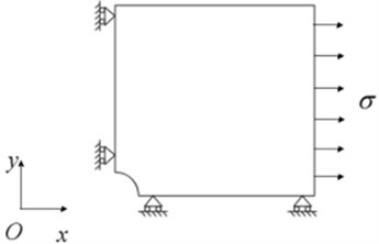
As the stress concentration caused by welding process has a minor effect to strain releasing than that of drilling a hole, the joint is simplified as a thin plate. And we use shell element to conduct a FEM numerical analysis. Considering the symmetry and boundary conditions, we establish the FEM model with just a quarter of the joint structure, whose dimension is 30 mm×30 mm. And we choose hole-drilling diameter 4 mm 0.5 mm, 1.0 mm, 2.0 mm, 3.0 mm, and 4.0 mm respectively to study the influence of the hole diameter, shown as Fig. 1. In engineering practice, we usually divide the welding joints into four zones: the weld zone, the fusion zone, the heat affect zone, and the base metal. The material properties of this four zones are not exactly the same, but their differences are not much. Therefore, to simplify the modeling process, we use a macro-constitutive model (established according to the proprieties of base metal) of the joint to substitute the regions with different constitutive relations, shown as Fig. 2.
Fig. 1Simulation model of the plate with joint
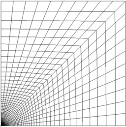
a) Before drilling

b) 0.5 mm
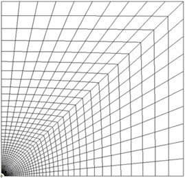
c) 1.0 mm
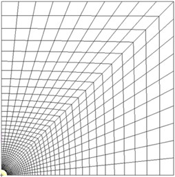
d) 2.0 mm
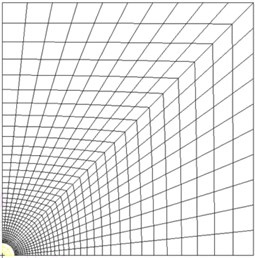
e) 3.0 mm
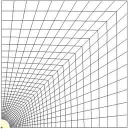
f) 4.0 mm
By abstracting the displacement of grid nodes at the corresponding raster positions of strain gauges shown as Fig. 3, the strain value can be calculated. The boundary conditions in finite element model are given as: restraining the translation of -direction on the left side, the translation of -direction on the down side, no rotations in these two sides, and a uniform pressure is applied on the right side of the plate, shown as Fig. 4. The applied pressures were 70 MPa, 80 MPa, 120 MPa and 130 MPa, respectively.
Fig. 2The curve of macro stress in relation to strain of the joint
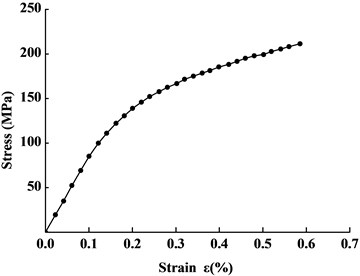
Fig. 3Displacement-extracting points
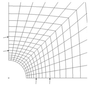
Fig. 4Boundary conditions in finite element model
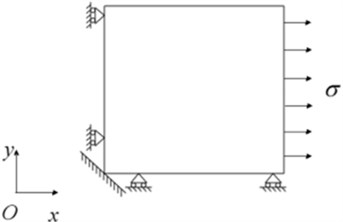
a) Before drilling
b) After drilling
3.2. Simulation results
According to the nonlinearly static FEM analysis, in combination with Eq. (4), the corrected strain releasing coefficients considering plastic deformation are given as
1) 0.5 mm:
2) 1.0 mm:
3) 2.0 mm:
4) 3.0 mm:
5) 4.0 mm
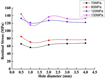
Then the residual stress of 2219-T87 aluminum alloy joints can be calculated under different hole diameters according to Eqs. (1), and (5) to (9), the results are showed in Fig. 5. We can see from the figure that the curve of residual stress in relation to hole diameters presents a decline at 1.0 mm; and the welding residual stress becomes more stable after when 2 mm.
Fig. 5The curve of residual stress in relation to hole-drilling diameter
3.3. The influence of hole-diameter to estimation
Table 1Standard deviations
(mm) | |
0.5 | 20.30 |
1.0 | 21.88 |
2.0 | 12.70 |
3.0 | 7.42 |
4.0 | 4.86 |
In order to evaluate the influence of different hole diameters to residual stress estimation, the concept of standard deviation is used to describe the statistical dispersion. It has been calculated under different hole diameters through Eq. (10), results are listed in Table 1. We can see the standard deviation of residual stress and calibrated value is minimum when the hole-drilling diameter is 4.0 mm, which indicates that the estimation result is most reliable and stable when 4 mm. Thus, in the subsequent measuring test, we will drill a 4 mm hole in the joint to estimate the residual stress:
4. Measurement test on residual stress
4.1. Test sample
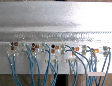
The test sample is 2219-T87 aluminum alloy welding joint with a thickness of 4.0 mm, shown as Fig. 6, and holes of 4 mm are drilled in the sample by drilling equipment at different measuring points listed in Table 2. Here, the variable represents the distance between measuring points and the welding seam.
Table 2Specific locations of measuring points
Measuring point number | 1 | 2 | 3 | 4 | 5 |
(mm) | 2 | 4 | 6 | 8 | 10 |
Fig. 6Test sample after drilling holes
4.2. Test results and analyses
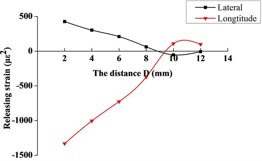
The releasing strain obtained by the test is shown in Fig. 7, which describes the relationship between the releasing strain and distance . From the two curves in the figure, it can be seen that the longitudinal releasing strain has a dominant role in residual stress calculation. So the lateral releasing strain can be ignored in the estimation of residual stress.
Fig. 7The variation curve of release strain
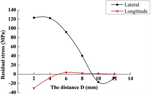
Based on the releasing strain, the distortion energy density calculated by Eq. (4) are listed in Table 3. Then the residual stress at welding region can be obtained through Eq. (1) and (9), the stress distribution is described as Fig. 8. We can clearly see that the residual stress is first tension stress when distance , it then becomes compressive stress when . And the maximum residual stress calculated under the hole diameter of 4.0 mm is 123.2 MPa.
Table 3Results of S at different points
Measuring point number | (mm) | () | () |
1 | 2 | 1456376.550 | 6.163 |
2 | 4 | 817650.951 | 5.913 |
3 | 6 | 399650.733 | 5.602 |
4 | 8 | 74225.855 | 4.871 |
5 | 10 | 11222.113 | 4.050 |
6 | 12 | 9326.412 | 3.970 |
Fig. 8The variation curve of residual stress
5. Conclusions
In this paper, the method of hole-drilling in combination with FEM numerical simulation are applied to estimate the welding residual stress. In the process of FEM simulation, the influence of drilling-hole diameter has been analyzed. And the residual stress of 2219-T87 aluminum alloy welding joints has been calculated. The conclusions are submitted as followed.
1) The simulation results show that the minimum deviation of the estimation stress values and calibration stress values is 4.86 % when the hole-drilling diameter is 4.0 mm. That is to say 4 mm is the optimal hole diameter for estimation.
2) The residual stress obtained by estimation under this optimal hole diameter has a distribution of first tensile stress and then compressive stress from the welding seam to outward. And the maximum residual stress of the welding joint sample is 123.2 MPa.
3) The research results prove that the method of estimating residual stress with considering the influence of hole diameter for welding structures is reliable and valid in engineering.
References
-
Malarvizhi S., Balasubramanian V. Effect of welding processes on AA2219 aluminium alloy joint properties. Transactions of Nonferrous Metals Society of China, Vol. 21, 2011, p. 962-973.
-
Wang Chunyan, Qu Wenqing, Yao Junsan, Zhao Haiyun 2219-T87 aluminium alloy friction stir welding head organization and mechanical properties. Transactions of the China Welding Institution, Vol. 31, 2010, p. 77-84, (in Chinese).
-
Wang Qingming, Sun Yuan Research development on the test methods of residual stress. Journal of Mechanical & Electrical Engineering, Vol. 28, 2011, p. 11-15, (in Chinese).
-
Liu Qianqian, Liuzhaosan, Song Sen Research status of measurement for residual stress. Machine Tool & Hydraulics, Vol. 39, 2011, p. 135-138, (in Chinese).
-
ASTM E837-81. A standard method for determining by the hole-drilling method.
-
Zhao Haiyan, Pei Yi, Shi Yaowu The influence and correction to the measuring error of high welding residual stress when using hole-drilling method. Journal of Mechanical Strength, Vol. 18, 1996, p. 17-26, (in Chinese).
-
Christopher J. Lmmi, Diana A. Lados Numercial predictions and experimental measurements of residual stress in fatigue crack growth specimens. Engineering Fracture Mechanics, Vol. 78, 2011, p. 1114-1124.
-
Masubuehi K. Prediction and control of residual stresses and distortion in welded structures. Theoretical Prediction in Joining and Welding, Vol. 16, 1996, p. 71-88.
-
Chen Yong, Gao Deping, Chen Shixuan Determination of the residual stresses in EBW joint of titanium alloy plate by hole-drilling method. Physical Testing and Chemical Analysis Parta Physical Testing, Vol. 37, 2011, p. 427-430, (in Chinese).
-
Liljedahl C. D. M., Brouard J., Zanellato O. Weld residual stress effects on fatigue crack growth behavior of aluminum alloy 2024-T351. International Journal of Fatigue, Vol. 31, 2009, p. 1081-1088.
-
Lemmen H. J. K., Alderliesten R. C., Pieters R. R. G. M., Benedictus R., Pineault J. A. Yield strength and residual stress measurements on friction stir welded aluminum alloys. Journal of Aircraft, Vol. 47, 2010, p. 1570-1583.
-
Suresh S., Giannakopoulos A. E. A new method for estimating residual stress by instrumented sharp indentation. Acta Materialia, Vol. 46, 1998, p. 5755-5767.
-
Webster G. A., Ezeilo A. N. Residual stress distributions and their influence on fatigue lifetimes. International Journal of Fatigue, Vol. 23, 2001, p. 375-383.
-
Rodrigues D. M., Menezes L. F., Loureiro A., Fernandes J. V. Numerical study of the plastic behaviour in tension of welds in high strength steels. International Journal of Plasticity, Vol. 20, 2004, p. 1-18.
About this article

The authors acknowledge the financial supports from Jiangsu Provincial Natural Science Foundation of China (No. BK2012795), Operating Expenses of Basic Scientific Research Project (No. NS2014009) and Priority Academic Program Development of Jiangsu Higher Education Institutions.
