Abstract
A macro-micro manipulator (M3) system, composed of a rigid parallel manipulator serially mounted on a flexible cable suspended parallel manipulator, is used to precisely position the feed source of a super antenna. In order to reduce the impact of mechanical vibrations of the macro manipulator and achieve accurate positioning and orientating of the micro manipulator, a real-time motion planning based vibration control strategy is presented. This strategy comprises: (1) To determine the optimal position and orientation of the cable driven parallel manipulator, the real-time optimization is conducted according to the principle of uniform tension in the six driving cables; (2) Synchronized points and the “judge and wait” technique ensure the continuity and synchrony of the trajectory tracking of the two parallel manipulators; (3) The preadjustment of the micro parallel manipulator minimizes the drastic dynamical coupling as a result of its high-speed manipulation. Experimental results of the field model validate the high precision of the M3 system for super antenna when tracking a circular arc trajectory.
1. Introduction
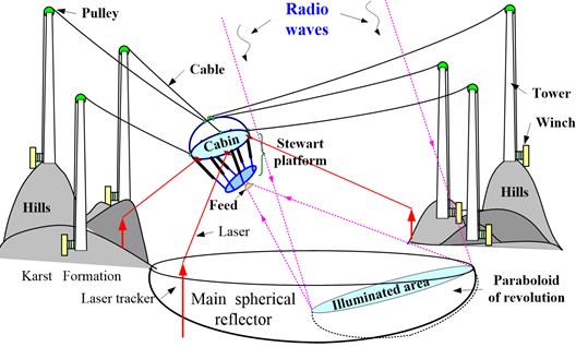
As one of the China’s major infrastructures of science, the five-hundred-meter aperture spherical radio telescope (FAST) is being built in the karst limestone formation in China [1]. FAST will be the largest single dish super antenna of the world, which is hoped to be a sophisticated tool for revealing the mystery of the universe. One of the prominent innovations of FAST lies in its special macro-micro parallel manipulator (M3) type structure for supporting the feed (the radio waves receiver). The M3 system integrating optical, mechanical and electronic technologies for the feed supporting structure effectively reduces its weight and cost [2]. As shown in Fig. 1, the six steel cables driven by servo motors and winches are the limbs of the macro parallel manipulator, with the semi-spherical cabin as the end-effector. A rigid parallel manipulator is mounted on the bottom of the cabin and the feed is fixed on the mobile platform (hence the name feed platform) of the Stewart platform. When observing a radio target, the trajectory for the feed will be as large as a circle with the radius of 186 m and height of 150 m. Further, the specifications for the position and orientation of the feed are pretty stringent. The real-time RMS of positioning and orientating error must be less than 10 mm and 8 arc-minute, respectively. So, the major goal of this M3 system application is to provide both a large manipulating workspace and high accuracy of the feed.
A considerable amount of research has been done on kinematics, dynamics and motion control of the rigid six-degree-of-freedom fully parallel manipulator in the case of the base is fixed on the ground [3, 4], but little on the two modified-type of parallel manipulator. One is the large-span cable instead of rigid extendable links driven parallel manipulator, which is also called cable suspended robot (CSR) in literature. The other is a parallel manipulator mounted on a compliant base like the end of a macro manipulator. A rigid (micro) robot mounted serially to the tip of a flexible (macro) robot is often used to increase reachable workspace, but flexibility of the macro manipulator makes it susceptible to vibrations [5]. In this research, the Stewart platform plays the role of a micro parallel manipulator, with the feed platform as its end-effector. Concerning the vibrations control of the macro manipulator and its effects on the end-effector trajectory, three different approaches have been conducted [6]. (1) damping the vibrations of the macro manipulator by using the dynamic forces applied upon its end-effector by the micro manipulator; (2) compensating for the effects of the micro-base motion on the Cartesian trajectory of the end-effector by correcting the trajectory of the micro manipulator in the joint space on-line; and (3) planning trajectories so that the end-effector excite as little macro flexible motion as possible while performing a specific task. Many researchers have investigated the first approach [5, 7, 8], in a majority of which [7, 8], the macro manipulator was modeled as a lumped mass-spring system for simplicity.
Fig. 1Overview schematic of FAST
Since the hardware limitation of the M3 system for the super antenna, the driving forces of limbs of both the macro and micro manipulators are without the accurate servo control. The first aforementioned approach is therefore unfit to be adopted for vibration control of this system. The objective of this research is to develop an effective motion planning scheme, which integrates the second and third approach mentioned above, of the M3 system to achieve the vibration control of the cabin and trajectory following control of the feed platform simultaneously.
2. Motion planning of the macro manipulator
Due to the unidirectional property of the cable, the cable suspended robots (CSR) are quite different from those driven by rigid links. CSRs can be divided into three categories [6]. First is the fully constrained robot which position and orientation can be determined by adjusting the cables length. It has been proved that for a CSR to be fully constrained, it must have at least seven cables. Second are the underconstrained CSRs in which the cables do not fully constrain the robot's configuration, and under the effect of external forces they will move. Usually the external force is gravity, and the robot tends to reach the equilibrium where its potential energy is minimal. The number of cables for underconstrained CSRs is six or less [9]. The third type of CSRs are point mass, where all the cables intersect at a single point while the robot is suspended underneath this point. This type of CSR has found application in cable suspended cameras.
In this research, the macro parallel manipulator uses six cables to control its position and orientation under the effect of gravity; it therefore is an underconstrained CSR consisting of six cables [10]. One degree-of-freedom out of the six is therefore uncontrollable, which is proved to be the rotation around the vertical axis of the cabin [11]. When the Euler angles convention is used to describe the orientation of the feed cabin, three angles , and are needed to compute the rotation matrix of the feed cabin relative to the global frame. And is the uncontrollable angle due to the underactuation property of this system.
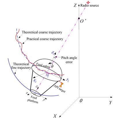
As shown in Fig. 2, provided the theoretical trajectory of the feed platform for the astronomical observation, the theoretical coarse trajectory for the feed cabin can be determined. The values of , , , and of the feed cabin can be obtained, and the inverse kinematics of the macro parallel manipulator can be performed if and only if is assigned. Thus, determining the value of of the cabin along its trajectory is the objective of the motion planning for the macro parallel manipulator. A real-time force optimization procedure is used to solve this problem. The motion of the macro parallel manipulator is considered as quasi-static states due to its low velocity, so the force equilibrium equations about the cabin in global frame can be formulated [12]. For simplicity, we take the form as follows:
where, is the Jacobian matrix, is the horizontal tension vector. is the load vector including forces and torques acted on the cabin and cables.
Fig. 2Trajectory of the macro-micro parallel manipulator system
Within a proper range for every assumed angle , the horizontal tension vector can be found for Eq. (1). In order to obtain the most approximately uniform tensions among the six cables, a force optimization procedure is mathematically described as the following form:
where gives an indication of the unidirectional action force of the cables. represents the force vector consisting of horizontal and vertical forces of th cable.
3. Motion planning of the micro manipulator
3.1. Determining orientation of the feed platform
The theoretical trajectory of the feed platform is taken as the desired tracking trajectory of the radio telescope. The axis of the platform points to the radio source to be observed all the time. However, in the control process, the desired orientation of the platform depends on the real-time position and orientation of the cabin.
The frame fixed on the cabin describes the position and orientation of the cabin. The frame fixed on the feed platform is describes the position and orientation of the platform. The position of the feed source on time is determined by the astronomical law of the radio source. The feed source is realized with circular polarization; therefore, the rotation of the feed source around its own symmetrical axis (local axis) does not affect the astronomical observation. For the observing purpose of FAST, only the pitch angle (the included angle between and axes) of the platform is of great importance. But for the robotic control of the Stewart platform, the position and orientation of the platform must be specified uniquely. So we choose:
where, is the unit vector of the axis in the global frame, Eq. (3) makes the feed source point to the radio object. The following Eq. (4) makes the Stewart platform tend to keep the initial configuration, so that the parallel manipulator has a high stiffness, precision and servo bandwidth:
Up to now, the orientation of the feed platform is determined.
3.2. Synchronizing of the macro-micro parallel manipulator
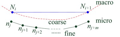
The purpose of this technique is to make the micro manipulator keep pace with the macro one. As shown in Fig. 3, the coarse and fine trajectories are discretized into many via points, respectively. is the th via point of the macro manipulator, while is the th via point of the micro manipulator. The distance between and is time-variant because the trajectory varies with the control application. The same situation applies to the fine trajectory via points.
Fig. 3Synchronized points of the trajectory
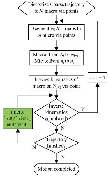
As for duration between two adjacent via points, the fine trajectory via points have the same duration. However, since the force optimization of Eq. (2) is performed with numerical method when the system works, and the number of iteration for the optimization does not always keep constant. Therefore, the adjacent two via points of coarse trajectory do not always have the same duration. So, if the macro and micro parallel manipulator are commanded to follow their own trajectory respectively, it is difficult for the feed platform to keep pace with the feed cabin. Additionally, it is not definite that how many fine via points associate with a pair of the coarse via points. Thus, the “judge and wait” synchronizing approach is proposed as shown in Fig. 4.
3.3. Preadjustment of the micro manipulator
Before the M3 system begins to track the desired trajectory, to make up the initial positioning and orientating error in a short period becomes an extra task for the Stewart platform. More often, this process needs high velocity of the Stewart platform for the limited time consumption. In general, the dynamical equations of the Stewart platform can be written as:
where is an inertia matrix, which is a symmetric and positive definite for all ; is the Coriolis/Centripetal vector; and are vectors containing gravity torques and actuation torques, respectively.
Fig. 4Flow chart of the “judge and wait” mechanism
A high speed motion of the feed platform leads to the large value of , what is more, the unsmooth acceleration of the feed platform produces a large value of . So for the fast process of the Stewart platform making up initial positioning and orientating error, there exist two potential effects as follow. First, from the kinematic and dynamic equations one can infer that high velocity of the Stewart platform needs high speed and large driving force of every active joint. This process then brings about the significant dynamical coupling between the Stewart platform and the feed cabin. Second, the actuators of the Stewart platform have the risk of triggering their safety limitations and switching off. Consequently, in order to minimize the dynamical coupling between the macro and micro manipulator, the following preadjustment scheme is presented.
Assume that the starting point of the theoretical trajectory is , where indicates the desired position and indicates the desired orientation. By the spatial transformation, we can obtain the starting point and ending point presented in the local frame of the micro parallel manipulator, and the left superscript denotes the local frame. The trapezoidal velocity profiles are used to plan the uniformly acceleration and deceleration motion of the feed platform. The entire motion is divided into three phases. First phase is the acceleration motion while the third phase is the deceleration motion, with the durations and spent respectively. Besides, the second phase is the uniform motion. The motion includes both translation and rotation of the feed platform. As for the acceleration time, can be equal to which implies that the translation and rotation acceleration will be finished simultaneously. The same situation applies to the deceleration time and .
When the total duration is given, the magnitudes of minimum linear and angular velocities and can be obtained by the following expression:
The magnitudes of maximum linear and angular velocities and can be obtained as follows:
Then the magnitudes of maximum linear and angular velocities and for the preadjustment can be obtained by the following expression:
where, the real numbers . Further, the time interval for linear acceleration, constant acceleration the time interval for angular acceleration constant angular acceleration can be obtained as following:
4. Experimental results and discussion
The experiments are conducted on the FAST 50 m model in Xidian University, which is constructed based on one tenth proportion of the FAST prototype. This scaled model is expected to verify the developed mathematical model and software and to validate the control and measurement strategy. Furthermore, researchers hope to draw rational conclusions regarding the FAST prototype from the FAST 50 m model.
The macro parallel manipulator for coarse tuning is driven by six large span steel cable servo systems, with the semi-spherical cabin as the end-effector. The cabin has a diameter of 1.0 m and a mass of 120.0 kg. Its center of gravity lies at the point located 4.9 cm vertically from the center of the bottom. The semi-spherical steel mask of the cabin can decrease the wind load. Inside the cabin, there is a steel beam structure to enhance the stiffness and to save space to hold the drive units of the micro parallel manipulator. As for the driving system of each cable, there are a extendable driving subsystem, a reducer, a wrench and two pulleys. The PID filter is used to achieve the position loop control of the servo motor. The extendable driving subsystem is comprised of an AC servomotor and drive unit, cycloidal reducer (reduction ratio: 1:60) and bobbin. The bobbin has a diameter of 0.4m and can carry 20 turns of the cable at most. The servomotor and driver used in this model are the PANASONIC MHMA 502 AC servomotor, with an incremental encoder (2500 P/Rev) and the matching MHDA 503 driver, respectively. The main motor parameters are: rated power 5 kW, rated torque 23.8 Nm, and rated speed 2000 rpm. The servo drive operates in the position mode and receives modulated pulses from a pulse distribution card developed by the authors. The card is embedded in the EISA socket of the micro tuning computer. The number of pulses indicates the motion value, and the frequency indicates the speed of each motor. The six cable towers symmetrically standing on the same circle with a diameter of 50 m have the same height of 21 m. The multi-stranded steel cable has a radius of 0.521 cm and a linear density of 0.14 kg/m. The ends of the six cables are connected to the feed cabin with spherical joints. Finally, the location of the joints has been optimized in order to meet the requirement of the 60-degree-pitch angle of the cabin. According to the motion planning of the cabin and inverse kinematics of the macro parallel manipulator, in which the cables are considered as catenaries due to their self-weight, the desired cable length of the six cables can be obtained and executed by the driving system.
The Stewart platform employs six high performance identical precision linear actuators (also called electrical cylinder) as driving limbs. The linear actuators used in the research are THOMSON TN-series TN-BK23-10-5A-10 with an incremental encoder (8192 P/5 mm). The linear actuator has a basic length of 146.1 mm and a stroke length of 254 mm. The main parameters are: maximum velocity 305 mm/s, maximum acceleration 7.7 m/s2, maximum thrust 2670 N, total mass 5.5 kg, and repeatability ±0.013 mm. The SynqNet network motion controller is used in the servo control of the electrical cylinders, so that the remote control of the Stewart platform can be realized. The parameters of the motion controller are: DSP Analog Devices SHARC 32-bit floating point, speed 40 MHz, update rate user programmable, velocity, acceleration, and jerk 32-bit floating point. The six drive units for the linear actuators are serially connected with an RJ-45 cable and then connected to the MEI network motion controller, which is inserted in the PCI socket of the micro tuning computer. The PID filter with feedforward is used for each electrical cylinder. The Stewart platform has a total mass of 37.3 kg. The six universal joints are distributed on a circle with the diameter of 720 mm. The central angle for each pair of joints is 87 degrees. The feed platform has a diameter of 280 mm, on which the spherical joints have a similar distribution with the 31-degree central angle. The task space of the Stewart platform is a sphere with a radius of 75 mm. The initial height of the feed platform in the cabin frame is – 630 mm.
In view of the large workspace of the cabin, the APITM (Automated Precision Instrument Inc) Tracker3-15 is used to conduct the non-contact laser measurement. With the six-degree-of-freedom target attached on the cabin, the real time position and orientation measurement of the cabin was obtained. The measuring data were updated with a frequency of 330 Hz. The position measuring accuracy of the laser tracker is 5 and the orientation measuring accuracy is 3 arc-seconds.
A series of experiments on the FAST50m model (Fig. 5) have been carried out. The position and orientation of the cabin is directly obtained with the API laser tracker. The position and orientation of the feed platform are calculated by the coordinate transformation and the forward position kinematics of the Stewart platform according to the feedback length of the six legs. In the following experiment, the platform is desired to track an arc trajectory, which has a radius of 4 m and a central angle of 90 deg. The desired linear velocity of both the cabin and platform is 0.5 cm/s. The wind speed is about 1.2 m/s, and the temperature is 28 deg. The experimental results of the macro-micro parallel manipulator system are as follows.
The curves in left figure of Fig. 6 represent the length of the six cables of the macro parallel manipulator. In general, the curves show the symmetry to a great extent. This result can be explained by both the rotational symmetry of the cable tower distribution and the reflection symmetry of the desired arc trajectory. The curve in right figure of Fig. 6 shows the value of described in Eq. (2). In order to make the tensions in six cables tend be identical, the feed cabin rotates around the central axis according to this curve. The symmetry appears again as a result of the symmetry of the connection points between the cabin and cables and the desired trajectory.
Fig. 5Photo of the 1/10 field model of FAST
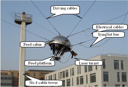
Fig. 6Length of the six cables (a) and θ (b) variation of the cabin
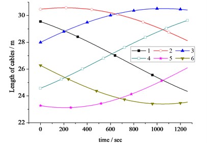
a)
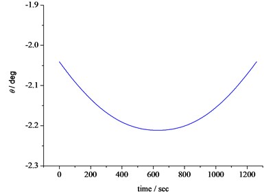
b)
As for the synchrony of the feed cabin and feed platform, the synchronized points are generated every 0.5 cm along the desired coarse trajectory as shown in Fig. 3. In correspondence to each step of the coarse trajectory, one hundred fine tuning via points are generated.
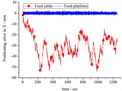
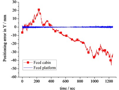
The positioning errors of the feed cabin and platform in , directions are shown in Fig. 7. It is shown that as a result of the flexibility of the six large span cables the positioning error in direction of the cabin (macro manipulator) is over 5 cm, while the positioning error of the feed platform (macro manipulator) is limited to 3 mm. The micro parallel manipulator has reduced the positioning error of the cabin in direction by 94 %. The positioning error in direction of the cabin is over 4 cm, while the positioning error of the feed platform is limited to 3 mm. Besides, the positioning error of the feed cabin in direction is generally limited into 4 cm due to the smaller desired displacement in this direction, while the positioning error of the feed platform is limited to 2.5 mm. The similar positioning error attenuation applies to the and direction. Besides, the amplitude of the platform errors is quite stable as shown in the figures listed above. The vibration control performance satisfies the positioning specifications.
In the experiments, preadjustment effectively reduces the dynamical coupling between the macro and micro parallel manipulator at the initial phase. This effect enhances the stability of the macro-micro parallel manipulator system. So, the fine tuning precision of the feed platform is achieved in the initial phase as shown in Fig. 7. These curves show that there exists little difference between the amplitudes of the positioning errors in the initial phase and that in other period.
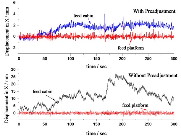
For comparison purpose, two trajectory tracking experiment with and without preadjustment are conducted, respectively. The desired trajectory is a line with the length of 150 cm. The initial position and orientation of the feed platform is . The final point of the preadjustment is .
Fig. 7Positioning error of the feed cabin and platform in X (a) and Y (b) directions
\
b)
Fig. 8 shows the positioning error curves of the feed cabin and feed platform in the two situations. Without the preadjustment, the Stewart platform is commanded to make up big error at the very beginning. In this case, the stronger dynamical coupling between the Stewart platform and the feed cabin results in a drastic oscillation of the feed cabin, and inferior positioning precision of the feed platform. The comparison validates the effectiveness of the preadjustment in vibration control of the M3 system.
Fig. 8Comparison of the errors with and without preadjustment
5. Conlusions
This paper has investigated the real-time motion planning based vibration and trajectory tracking control of the macro-micro parallel manipulator (M3) system for feed supporting of the super antenna. In order to uniquely determine the spatial position and orientation of the CSR-type macro parallel manipulator, an enumerative technique based real-time optimization procedure is conducted according to the principle of uniform tension in the six driving cables. Motion synchronization of the macro and micro parallel manipulators is achieved by designing a series of synchronized points and a “judge and wait” mechanism, which effectively ensures the continuity and synchrony of the trajectory tracking of the two cooperative parallel manipulators. Preadjustment of the micro parallel manipulator depresses the drastic dynamical coupling as a result of the fast movement of the micro manipulator by reducing the motion burden in advance. Experimental results of the FAST one tenth field model validate the motion planning and vibration control of the M3 system. The feed supporting, pointing and tracking system satisfies the demands of positioning and orientating precision with the desired tracking velocity.
References
-
Albus J. S., Bostelman R. V., Dagalakis N. G. The NIST robocrane. Journal of Robotic System, Vol. 10, Issue 5, 1993, p. 709-724.
-
Book W. J., Lee S. H. Vibration control of a large flexible manipulator by a small robotic arm. In Proceedings of the 1989 American Control Conference, Pittsburgh, USA, Vol. 2, 1989, p. 1377-80.
-
Dasgupta B., Mruthyunjaya T. S. The Stewart platform manipulator: a review. Mechanism and Machine Theory, Vol. 35, Issue 1, 2000, p. 15-40.
-
Fu S., Yao Y., Wu Y. Comments on “A Newton-Euler formulation for the inverse dynamics of the stewart platform manipulator” by B. Dasgupta and T. S. Mruthyunjaya [Mech. Mach. Theory, Vol. 33, 1998, p. 1135-1152]. Mechanism and Machine Theory, Vol. 42, Issue 12, 2007, p. 1668-1671.
-
George L. E., Book W. J. Inertial vibration damping control of a flexible base manipulator. IEEE/ASME Transactions on Mechatronics, Vol. 8, Issue 2, 2003, p. 268-271.
-
Capua A., Shapiro A., Shoval S. Spiderbot: A cable suspended mobile robot. In Proceedings of the IEEE International Conference on Robotics and Automation, Shanghai, China, 2011, p. 3437-3438.
-
Book W. J., Loper J. C. Inverse dynamics for commanding micromanipulator inertial forces to damp macromanipulator vibration. In Proceedings of the IEEE/RSJ International Conference on Intelligent Robots and Systems, Kyongju, South Korea, Vol. 2, 1999, p. 707-714.
-
Lew J. Y., Moon S. M. Active damping control of compliant base manipulators. In Proceedings of the IEEE/RSJ International Conference on Intelligent Robots and Systems, Kyongju, South Korea, Vol. 2, 1999, p. 812-817.
-
Bosscher P., Ebert-Uphoff I. A stability measure for underconstrained cable-driven robots. In Proceedings of the IEEE International Conference on Robotics and Automation, Piscataway, USA, Vol. 2004, Issue 5, 2004, p. 4943-4949.
-
Duan B. Y., Qiu Y. Y., Zhang F. S., Zi B. On design and experiment of the feed cable suspended structure for super antenna. Mechatronics, Vol. 19, Issue 4, 2009, p. 503-509.
-
Qiu Y. Y., Duan B. Y., Wei Q. Elimination of force singularity of the cable and cabin structure for the next generation large radio telescope. Mechatronics, Vol. 12, Issue 7, 2002, p. 905-918.
-
Du J., Bao H., Duan X., Cui C. Jacobian analysis of a long-span cable-driven manipulator and its application to forward solution. Mechanism and Machine Theory, Vol. 45, Issue 9, 2010, p. 1227-1238.
About this article

This work was supported by the National Natural Science Fund of China under Grant No. 51175397 and No. 51105290. The authors would also like to appreciate the Editor, Associate Editor, and the reviewers for their valuable comments and suggestions.
