Abstract
Prototypes of micro-robots and geometric path planning algorithms are presented in this paper. Geometric motion trajectories are generated by switching contacts, control points and tangents methods. Analysis of high-speed formation of trajectories using switching contacts method revealed that the geometric path depends on orientation angle of a micro-robot. Investigation of formation of high-precision trajectories demonstrated that there is minimal deviation from the given motion trajectory at which micro-robot stops. This paper presents methodologies for evaluation of optimal orientation angle of a micro-robot and minimum deflection from the given trajectory. The methodologies are verified by experiments.
1. Introduction
Most of the high-precision positioning devices that have been developed so far are driven by piezoelectric actuators [1-6], which possess high resolution, high stiffness and quick response. However, the strokes of piezoceramic transducers are extremely small.
R. Bansevičius and K. Ragulskis were the first who in 1989 presented 6-DOF and 9-DOF micro-robots that consisted of two kinematic pears: piezoelectric cylinder – passive sphere, piezoelectric disc – passive plane [7]. 3-DOF piezoelectric motor for motion or rotation by passive plane was proposed. It was piezoceramics mounted on metal plate and electrodes divided to equal 120° sectors [8]. Rotation is accomplished by means of travelling wave. During research work of positioning objects, piezoelectric ring-shaped, cylinder-shaped and hemisphere-shaped micro-robots were developed.
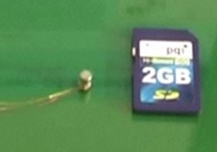
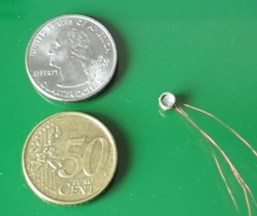
The potential application of these micro-robots is mini/micro lasers, in particular for industrial processes. As shown by experimental studies, the minimum dimensions of the micro robot can be reduced to a few millimeters (Fig. 1).
Fig. 13-DOF piezoelectric cylindrical actuators: a) 4 × 3 × 4 mm; b) 8 × 6 × 8 mm (D × d × h)
a)
b)
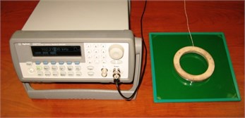
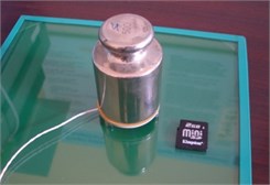
Piezoelectric ring-shaped micro-robotic schemes feature – ability to realize larger masses positioning systems (Fig. 2). In control of motion direction (without return communication systems) weight increase up to 500 g almost did not change motion parameters.
Fig. 2Cases of increased load capacity: a) piezoelectric ring 140 × 120 × 8 mm (D × d × h), frequency – 80 kHz, voltage – 80 V; maximum weight of positioning object – 2 kg; b) piezoelectric ring 40 × 10 × 2 mm (D × d × h), frequency – 80 kHz, voltage – 50 V; maximum weight of positioning object – 500 g
a)
b)
Different trajectory planning methods are used for autonomous robots. Generally, polynomial of any degree [9], splines [10, 11] and clothoids curves [12, 13] interpolation between points. These methods are not used for planning the trajectory of designed micro-robot because, in our case, only one electrode segment is active for straight line motion and all electrode segments are active for rotary motion. Their motion direction depends on active contact point (there are three contact points). Thus their motion trajectory is a broken line. Also, they have high resolution motion and wide range of speed control.
Motion path-planning algorithms for these 3-DOF micro-robots under various contact-excitation schemes were created: switching contacts, control points and tangents methods.
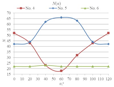
Results of research of switching contacts algorithm demonstrated that quantity of switching contacts is inversely proportional to deviation from given trajectory and angle between orientation angle of a micro-robot (angle between the first contact of micro-robot and x axis). Dependence is observed to be nonlinear [14, 15]. In high-speed formation of trajectories it is important to minimize the number of switching contacts. Though, the exact dependency between quantity of switching contacts and orientation angle of micro-robot is not set in the previous research. Consequently one of the research tasks was to specify this dependence N(α), when motion trajectory is planned with switching contacts method.
Analysis of displacement length of micro-robot demonstrated that after the reduction of the deviation from the given trajectory (ε), length of displacements starts to decrease rapidly as well [15]. However, this study did not examine the minimum limit of the deviation value at which displacement length is approaching to the motion resolution of a micro-robot (Pmin). There is the smallest deviation (εmin) at which micro-robot can still move. But if ε < εmin, robot stops. Knowing the minimum deviation, it is possible to generate the precise motion trajectory. Calculations of the smallest deviations for each path-planning method are described and analyzed in this paper too.
2. Overview of path-planning methods
Micro-robot motion trajectory can be formed, when given motion trajectory is described by parametric functions by formula:
where – parameter of parametric function, – nodes of given trajectory, – number of node.
According to the requirements of the task, the axis of symmetry of micro-robot must deviate as little as possible from the given trajectory . Therefore, must be defined maximum allowable deviation from function . Coordinates located distance from given trajectory are called coordinates of the boundary.
If one electrode segment of micro-robot is active at a time, then motion trajectory is broken line. Switching contacts algorithm described in [14] were developed for this kind of motion (Fig. 3).
Fig. 3Example of motion trajectory formation with switching contacts method
If all three electrode sectors of micro-robot are excited at a time with phase difference 120°, running wave is generated leading to rotary movement. In this case, micro-robot will rotate around its central axis. Rotation can be clockwise and counter-clockwise. Control points (Fig. 4(a)) and tangents path (Fig. 4(b)) formation algorithms were developed using these two excitation schemes.
Fig. 4Examples of trajectory formation: a) control points method; b) tangents method
a)
b)
Control points method principle is to divide given trajectory into equal length segments, and to make rotation check in points joining these segments evaluating motion resolution. These points are called control points. The method is suitable for the motion in continuous curves. This method was developed to form a high-precision trajectory [16].
Method of tangents is designated to shape the trajectory that is optimal with respect to speed, but still maintains the accuracy of motion. First, it is checked, if there is possibility to move from current node to another without intersecting boundary coordinates. If boundary coordinates are intersected, then it is searched for the tangent point at boundary coordinates and the point of motion coordinates is calculated [17].
3. Motion trajectory generation parameters
During research of switching contacts quantity, it was demonstrated that orientation angle of micro-robot affects this parameter. If right orientation angle of micro-robot is selected, then high-speed trajectories could be formed. This angle is called optimal orientation angle and for any kind of given trajectories it could be calculated by weighted average formula:
where – quantity of given trajectory segments between nodes, – length of segment between nodes, – angle between segment and axis, – segment number.
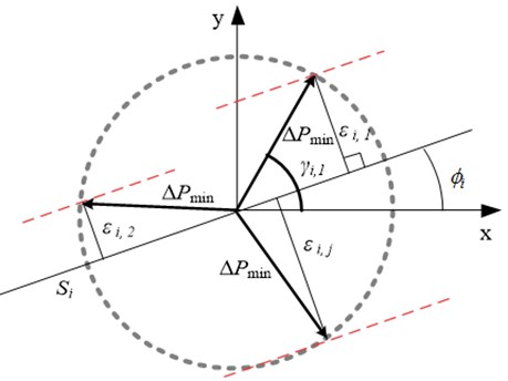
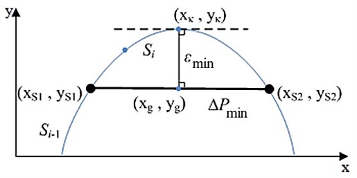
The smallest deflection from given trajectory (Fig. 5) could be calculated by formula, when trajectory formation method is switching contacts:
where , where – number of electrode segment, – motion resolution, – angle between electrode segment and x axis, – micro-robot orientation angle, – angle between two nodes segment and axis, – number of segments between nodes.
Fig. 5Scheme of setting of minimum deviation from given trajectory
When control points or tangents methods are used for trajectory generation, permissible generated trajectory deflection from the given trajectory (Fig. 6) could be calculated by formula:
where – coordinate at given trajectory, where curvature of curve is maximum, coordinate is calculated by solving system of equations:
where , – coordinates of planned trajectory, – parameter of parametric function, where curvature of curve is maximum.
Fig. 6Scheme for determining maximum deflection
4. Analysis of planned motion trajectories
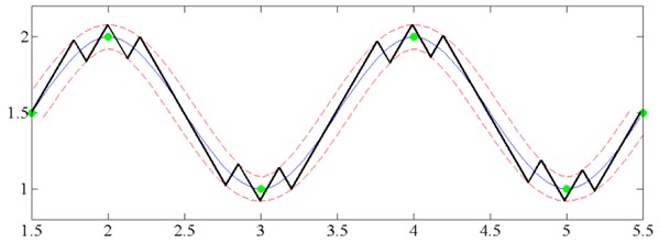
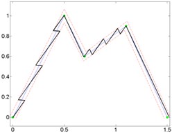
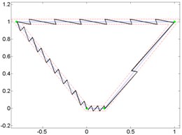
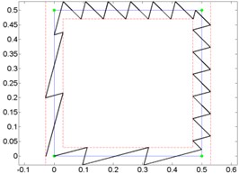
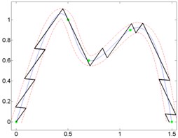
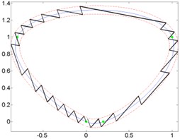
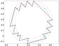
To determine, whether the trajectory type affect optimal orientation angle, broken lines trajectories (Fig. 7) and curves (Fig. 8) between the same nodes were formed and planned motion trajectories using switching contacts algorithm. For testing optimal orientation angle calculation formula (2) three kinds of trajectories were selected: open trajectory (Fig. 7, 8a), closed trajectory with different segments length (Fig. 7, 8b) and closed trajectory with the same segments length (Fig. 7, 8c).
Results of optimal angle calculations by using formula (2) is shown in Table 1, where – quantity of switching contacts at calculated angle.
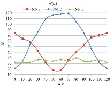
All the calculation results were compared with the experimentally established dependences of orientation angle of micro-robot. Results of experiments are provided in Fig. 9.
Fig. 7Given broken line and generated micro-robot motion trajectories with switching contacts method: a) No. 1; b) No. 2; c) No. 3
a)
b)
c)
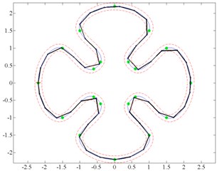
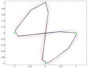
Fig. 8Curves and generated micro-robot motion trajectories with switching contacts method: a) No. 4; b) No. 5; c) No. 6
a)
b)
c)
Results of analysis indicate that it does not matter, which kind of trajectory is given. Minimal and maximal quantity of switching was at the same orientation angle, when motion resolution is constant.
Permissible deviation of the generated trajectory from the planned one (Fig. 10, 11), which depends on the piezorobot motion resolution and on the type of trajectory, was calculated and experimentally defined during the investigation.
Table 1Results of optimal orientation angle calculation
Trajectory No. | , o | |
1 | 16 | |
4 | 18 | |
2 | 39 | |
5 | 42 | |
3 | 35 | |
6 | 24 |
Fig. 9Experimentally established dependencies of orientation angle of micro-robot, when given trajectories are: a) broken lines; b) curves
a)
b)
Fig. 10The smallest deviation dependence on the motion resolution, when using switching contacts algorithm
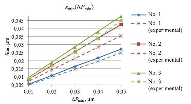
Results of experiment revealed that the smallest deflection calculation methodology is right for each path-planning method.
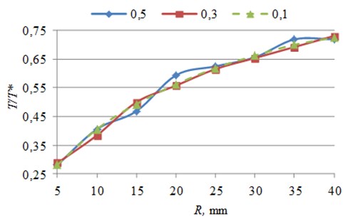
Motion trajectory formation with control points method was analyzed according to the minimum angular displacement. Three points were selected. Trajectory, which segments are close to straight line, was planned. It was demonstrated that quantities of switching contacts depend on the inner radius R of a micro-robot. Generated trajectory switching contacts quantity T and control point’s quantity T* ratio was calculated, when minimum displacement is 0.5, 0.3 and 0.1 µm (Fig. 12).
Results of experiment showed, that changing motion resolution leaves quantity T and control point’s quantity T* ratio almost constant.
Fig. 11The smallest deviation dependence on the motion resolution, when using control point’s algorithm and tangents algorithm
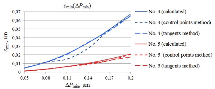
Fig. 12Generated trajectory switching contacts quantity and control point’s quantity ratio dependence on inner radius of piezorobot
5. Conclusions
In order to increase the motion speed the optimal angle of a micro-robot must be calculated, when motion trajectory is generated using switching contacts method. Advantage of this method is its simplicity in executing control of a micro-robot.
Methodology for calculation of minimum deflection from the planned trajectory was created for each trajectory generation method. Evaluation of this parameter allows predicting critical stops of the micro-robot. Taking into account the geometrical dimensions of the robot, and the minimum deviation, it is possible to achieve high-precision trajectory generation.
References
-
Richard M., Clavel M. Concept of modular flexure-based mechanisms for ultra-high precision robot design. Mechanical Sciences, Special Issue on Future Directions in Compliant Mechanisms, Vol. 2, 2011, p. 99-107.
-
Chi Hsiang Pan, Sz Sheng Tzou, Ruei Yang Shiu A novel wireless and mobile piezoelectric micro robot. Proceedings of the 2010 IEEE International Conference on Mechatronics and Automation, August 4-7, Xi'an, China, 2010, p. 1158-1163.
-
Varma V. K., Dixon W. E. Design of a piezoelectric meso-scale mobile robot: a compilant amplification approach. Proc. of the 2002 IEEE Int. Conf. on Robotics & Automation, Washington, 2002, p. 1137-1142.
-
Shaoze Yan, Fuxing Zhang, Zhen Qin, Shizhu Wen A 3-DOFs mobile robot driven by a piezoelectric actuator. Smart Mater. Struct., Vol. 15, Issue 1, 2006.
-
Martel S. Fundamental principles and issues of high-speed piezoactuated three legged motion for miniature robots designed for nanometer-scale operations. International Journal of Robotics Research, Vol. 24, Issue 7, 2005, p. 575-588.
-
Simu U., Johansson S. Analysis of quasi-static and dynamic motion mechanisms for piezoelectric miniature robots. Sensors and Actuators A: Physical, Vol. 132, Issue 2, 2006, p. 632-642.
-
Ragulskis K., Bansevičius R., Barauskas R., Kulvietis G. Vibromotors for Precision Microrobots. Hemisphere Publishing Corp., USA, 1988, 310 p.
-
Bansevičius R. Latest trends in the development of piezoelectric multi-degree-of-freedom actuators/sensors. Responsive Systems for Active Vibration Control (NATO Science Series II: Mathematics, Physics and Chemistry), 2002, p. 207-238.
-
Cuevas E., Zaldívar D., Rojas R. Walking Trajectory Control of a Biped Robot, 2004.
-
Tang Z., Sun Z., Zhou C., Hu L. Reference trajectory generation for 3-dimensional walking of a humanoid robot. Tsinghua Science and Technology, Vol. 12, Issue 5, 2007, p. 577-584.
-
Ata A. A., Johar H. Trajectory planning of a constrained flexible manipulator. Kordic V., Cutting Edge Robotics, I-Tech, 2005.
-
Shanmugavel M. Path Planning of Multiple Autonomous Vehicles. Cranfield University, 2007.
-
Delingette H., Hebert M., Ikeuchi K. Trajectory generation with curvature constraint based on energy minimization. Journal Intelligent Robots and Systems '91, Intelligence for Mechanical Systems, Proceedings IROS '91, 1991.
-
Bansevičius R., Drukteinienė A., Kulvietis G., Mažeika D. Switching leg method for trajectory planning of mobile piezorobot. Journal of Vibroengineering, Vol. 12, Issue 1, 2010, p. 26-33.
-
Bansevičius R., Drukteinienė A., Kulvietis G. Path-planning algorithms analysis of hemispheric mobile piezorobot. Research Communications of the 17th International Conference on Information and Software Technologies, 2011.
-
Bansevičius R., Drukteinienė A., Kulvietis G. Trajectory planning method of rotating mobile piezorobot. Journal of Vibroengineering, Vol. 11, Issue 4, 2009, p. 690-696.
-
Drukteinienė A. Trajectories Formation for Mobile Multidimensional Piezorobots with Nanometer Resolution. Doctoral Dissertation, Vilnius Gediminas Technical University, Technika, 2011.
About this article

This work has been supported by Research Council of Lithuania (Project No. MIP-075/2012) and the Lithuanian Agency for Science, Innovation and Technology (Project No. 31V14/12).
