Abstract
Varieties of structural damage identification methods have been proposed in the past years. Most of the methods adopt modal information including modal frequencies and mode shapes. These methods provide excellent references for researchers and engineers in this field. However, there is still an unsolved critical problem regarding the number of modes that should be used in the identification. To circumvent this problem, a two-step method for determination of mode order is proposed. Modal effective mass analysis is used to estimate the range of mode orders in the first step. Stabilization diagram analysis is then employed in the second step to decide the reasonable mode order. In the numerical simulation, the proposed method is used to determine the mode order in the damage localization of a truss structure. Results demonstrate that all of the damaged elements are correctly identified when adopting reasonable mode order determined by the proposed method.
1. Introduction
Structures begin to deteriorate once they are built and used. Maintaining safe and reliable structure for daily use is a topic that has received considerable attention in recent years. Usual inspection techniques require the portion of the structure being inspected to be readily accessible and are therefore not appropriate due to interference with operational conditions. By definition, non-destructive techniques are the means by which structures may be inspected without disruption or impairment of serviceability. Some techniques are based on visual observations and some are based on the properties of the material. Other techniques are based on the interpretation of the structural condition by observing the change in the global behavior of the structure. The use of vibration test data to determine structural characteristics falls into this last category and are the subject of this paper.
In the past decades, varieties of vibration-based damage identification methods have been proposed to identify the occurrence, the location and the qualification of damage [1]. Most of the methods adopt experimental modal information including modal frequencies and mode shapes. Ojalvo et al. [2] proposed a method to locate the model errors by their relevant degrees of freedom using modal force residues. Messina et al. [3] proposed to use a multiple damage location assurance criterion, which is formulated on the same basis as the modal assurance criterion, to locate the damaged elements. Shi et al. [4, 5] proposed a method to localize the damaged element by comparing the modal strain energy of element before and after the damage. The modal strain energy change ratio (MSECR) of each element is defined to be a damage indicator. Recently, methods [6, 7] have been proposed to use the information fusion technique to integrate the damage identification results from different indicators. Also some applications of vibration-based damage identification in practice have been presented [8-10]. These studies provide excellent references for researchers and engineers in this field. However, of all the damage identification methods based on modal information, critical problem remains unsolved that how many modes should be used in the identification.
This paper presents the study on mode order determination in damage identification of a truss structure using accumulative damage localization method. The paper is organized as follows: in Section 2, the accumulative damage localization method to be used in the numerical simulation is briefly described. In Section 3, mode order determination method based on modal effective mass and stabilization diagram is proposed. Numerical simulation is given in Section 4.
2. Accumulative damage localization method
Dempster-Shafer (DS) evidence theory is developed to fuse data from different information sources [8]. Damage identification using evidence theory has been proposed to fuse indicators from different damage identification methods [6]. Then, the evidence theory is further applied in accumulative damage localization method to fuse damage identification results from different modes. The method will be used in this study and it could be briefly described as follows [7]:
Suppose there are n elements in the structure. These elements are treated as subsets in the DS evidence theory. Damaged elements are preliminarily localized using certain method from S orders of structural modes. Damage indicators from these modes are:
where is the damage indicator for th element from th mode.
These indicators should be preprocessed to assign the basic probability for each element before fusing. The basic probability is calculated as follows:
where represents the processed indicator, as well as the basic probability for th element from th mode. Then, Fused Damage Indicator (FDI) could be computed according to the combination rule:
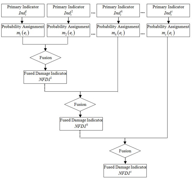
is a measure of conflict between the different sources. Then, FDI are normalized with respect to the maximum value. And, the normalized results are defined as Normalized Fused Damage Indicator (NFDI). The accumulative fusing procedure could be illustrated as the flowchart shown in Fig. 1. is the normalized fused damage indicator in th step. In each step, Eq. (3) and (4) are used to fuse and the th group of processed primary indicator.
In this study, damage indicator is (Modal Strain Energy Change Ratio) defined as follows [4, 5]:
where and denote the element number and mode order respectively. And and are the undamaged and damaged defined as follows:
is th undamaged element stiffness matrix. and are th mode shapes of the undamaged and damaged element respectively. The undamaged stiffness matrix is used in the damaged state as an approximation. Damage is assumed to cause a local stiffness reduction affecting the mode shapes in a localized region. will change a little in the undamaged elements, but will change much greater in the damaged elements.
If several modes are adopted in the damage identification, Shi [4, 5] proposed to use, which is the average of for all the modes, as the damaged indicator. However, it is proved that should be accumulatively fused instead of simply averaged to get better identification result [7].
Fig. 1Flowchart of accumulative localization fusion
3. Determination of mode orders based on modal effective mass and stabilization diagram
3.1. Modal effective mass
Consider a discrete dynamic system governed by the following equation:
where and are the system stiffness and mass matrices, and are the acceleration vector and displacement vector respectively, is the forcing function.
Let be the eigenvector matrix. The system’s generalized mass matrix is given by:
Let be the influence vector which represents the displacements of the masses resulting from static application of a unit ground displacement. Define a coefficient vector as:
The modal participation factor matrix for th mode is:
The modal effective mass for th mode is:
The modal effective mass could be used to judge the significance of a vibration mode and be employed to estimate the number of modes included in structural damage identification.
3.2. Determination of mode orders using modal effective mass and stabilization diagram
Suppose there are modes adopted in the damage identification, the sum of modal effective mass of these modes is:
The ratio r between and the total structural mass should be less than 1 and more than a certain number, e.g., 0.95:
where is the total structural mass.
Therefore, the number of modes should be more than the number of modes which makes equal to 0.95 and less than the number of modes which makes close to 1:
is the number of modes which makes equal to 0.95 and is the number of modes which makes close to 1.
To determine the mode orders included in the damage identification, several identifications should be performed using mode orders from to , these results are then plot as stabilization diagram with the mode order as the -axis and the element No. as the -axis. The decision could finally be made considering results from both the modal effective mass analysis and stabilization diagram analysis.
4. Numerical simulation
4.1. GARTEUR truss structure
The proposed method is applied in the damage localization of a GARTEUR truss structure shown in Fig. 2. The GARTEUR structure has two points fixed to the base. The FE model of the GARTEUR structure consists of 36 2-D beam elements. Each beam segment is a superposition of an axial bar element and a bending beam element. Each node of the beam element has three DOFs (two translations and one rotation) and hence, the total number of DOFs in the FE model is 90. Following material properties are used during FE modeling: Young’s modulus is assumed to be 0.75×10¹¹ N/m2 and density 2800 kg/m3. For the bar element, the cross-sectional areas is 0.004 m2. For the bending beam elements, the second moment of area is assumed to be the same for all the elements and is assumed to be 0.0756 m4.
Fig. 2The GARTEUR structure
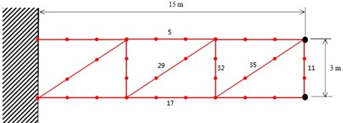
In order to generate the simulated experimental data, stiffness modeling errors are introduced in the elements of the analytical model by changing the second moment of area (I) of some of elements as shown in Table 1 and Fig. 2.
Table 1Stiffness modeling error location
Element No. | 5 | 11 | 17 | 29 | 32 | 35 |
error (%) | -10 | -10 | -10 | -10 | -10 | -10 |
4.2. Modal effective mass analysis and stabilization diagram analysis
Modal effective masses of the first 24 modes are listed in Table 2. According to equations (13) to equation (15), the number of mode order should be 2 to 4.
The identification results with different numbers of mode orders are plotted as stabilization diagram in Fig. 3. It could be observed that when the mode order is 3 to 6, the identification results are the same. However, according to the result of modal effective mass analysis, 5th and 6th mode are not necessary to be used due to their minor contribution to the modal effective mass. Therefore, mode order should be 4 in the damage identification to get the maximum modal effective mass and the least computation cost.
4.2.1. Damage identification result
Fig. 4 provides the damage identification result when mode order is 4. Comparing the result with Table 1, it is obvious that all of the six simulated damaged elements are correctly identified.
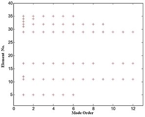
Fig. 3. Stabilization diagram of damage identification results
Fig. 4Damage identification result when s= 4
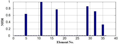
Table 2Modal effective mass
Mode No. | Modal effective mass | ||
Translation DOF 1 | Translation DOF 2 | Rotation DOF | |
1 | 7.74E-02 | 3.81E+02 | 5.08E+04 |
2 | 5.07E+02 | 4.33E-02 | 1.29E+03 |
3 | 5.21E+01 | 1.58E+01 | 2.75E+00 |
4 | 1.04E+01 | 1.02E+02 | 1.69E+03 |
5 | 1.51E+01 | 1.11E+00 | 1.57E+01 |
6 | 3.25E-02 | 5.09E-01 | 6.82E+00 |
7 | 4.51E-03 | 1.62E+01 | 8.99E+01 |
8 | 1.13E-04 | 2.85E+00 | 8.06E+00 |
9 | 1.27E-04 | 8.35E-01 | 7.14E-01 |
10 | 6.80E-01 | 4.51E-01 | 1.33E+01 |
11 | 6.48E-02 | 8.19E-04 | 3.44E+01 |
12 | 1.77E-02 | 6.07E+00 | 1.12E+01 |
13 | 6.03E+00 | 3.89E-01 | 4.78E+00 |
14 | 1.26E+00 | 2.53E+00 | 3.54E+00 |
15 | 3.36E+00 | 1.34E+01 | 1.20E+02 |
16 | 6.93E-01 | 5.37E+00 | 1.35E+01 |
17 | 7.78E-02 | 1.35E+00 | 3.82E+00 |
18 | 9.12E-02 | 5.78E-02 | 7.99E-01 |
19 | 3.72E-03 | 1.28E-01 | 6.28E-01 |
20 | 3.80E-01 | 3.85E-02 | 2.18E-02 |
21 | 1.44E+00 | 2.47E+00 | 3.75E+01 |
22 | 1.14E+00 | 2.70E+00 | 7.85E+00 |
23 | 2.10E-03 | 2.82E-01 | 6.21E-01 |
24 | 9.88E-01 | 2.42E+01 | 5.84E+01 |
5. Conclusions
This paper presents the study on mode order determination in damage identification using modal information. A two-step mode order determination method is proposed using modal effective mass analysis and stabilization diagram analysis. Damage identification of a GARTEUR truss structure is studied in the numerical simulation. Results indicate that all of the damaged elements are correctly identified when adopting mode order determined by the proposed method.
References
-
A. Alvandi, C. Cremona Assessment of vibration-based damage identification techniques. Journal of Sound and Vibration, Vol. 292, Issue 1-2, 2006, p. 179-202.
-
I. U. Ojalvo, D. Pilon Diagnostics for geometrically locating structural math model error from modal test data. Proceedings of the 29th AIAA SDM Conference, 1988.
-
A. Messina, E. J. Williams, T. Contursi Structural damage detection by a sensitivity and statistical-based method. Journal of Sound and Vibration, Vol. 216, Issue 5, 1998, p. 791-808.
-
Zhiyu Shi, S. S. Law, Lingmi Zhang Structural damage localization from modal strain energy change. Journal of Sound and Vibration, Vol. 218, Issue 5, 1998, p. 825-844.
-
Zhiyu Shi, S. S. Law, Lingmi Zhang Structural damage detection from modal strain energy change. Journal of Engineering Mechanics, Vol. 126, Issue 12, 2000, p. 1216-1223.
-
H. Y. Guo Structural damage detection using information fusion technique. Mechanical Systems and Signal Processing, Vol. 20, Issue 5, 2006, p. 1173-1188.
-
Qingguo Fei, Aiqun Li, Xiaodong Lu, Xiaolin Han Accumulative structural damage localization method and numerical simulation. International Journal of Terraspace Science and Engineering, Vol. 1, Issue 2, 2009, p. 87-97.
-
O. Huth, G. Feltrin, J. Maeck Damage identification using modal data: experiences on a prestresed concrete bridge. Journal of Structural Engineering, Vol. 131, Issue 12, 2005, p. 1898-1910.
-
Hong Guan, Vistasp M. Karbhari Improved damage detection method based on element modal strain damage index using sparse measurement. Journal of Sound and Vibration, Vol. 309, Issue 3-5, 2008, p. 465-494.
-
Manoj Kumar, R. A. Shenoi, S. J. Cox Experimental validation of modal strain energies based damage identification method for a composite sandwich beam. Composite Science and Technology, Vol. 69, Issue 10, 2009, p. 1635-1643.
-
G. Shafer A Mathematical Theory of Evidence. Princeton University Press, NJ, 1976.
About this article

The authors of the paper would like to express appreciation of the support from National Natural Science Foundation of China (10902024), Ministry of Education Program for New Century Excellent Talents in University (NCET-11-0086), Jiangsu Natural Science Foundation (BK2010397), and Foundation for Distinguished Young Teacher of Southeast University.
