Abstract
Since World War II, more vehicles have been lost to land mines than all other threats combined. Anti-vehicular (AV) mines are capable of disabling a heavy vehicle, or completely destroying a lighter vehicle. The most common form of AV mine is the blast mine, which uses a large amount of explosive to directly damage the target. Nowadays, V-shape hulls are widely used in armored demining vehicles to reduce the effects of mine blast. This paper presents the comparative results of dynamic analysis of the response of V-shape plate subjected to mine blast load using finite element analysis package ABAQUS. Various layers of materials like metals, lightweight foams and Balsa wood are used inside the V-shape plate to analyze their effects on the deformation of the plate and applied stresses and strains. The results indicate that application of aluminum and aluminum-foam leads to considerable reduction in deformation of the plate and consequently results in more energy dissipation and enhances crew survivability.
1. Introduction
According to the Landmine Monitor Report 2011 [1], Iran has been significantly contaminated with mines, primarily as a result of the 1980–1988 conflict with Iraq, affecting particularly the western region of country. In 2010, the number of casualties among humanitarian clearance operators was double that recorded for 2009. There were 131 deminer 10 casualties (36 deminers killed; 95 injured) recorded in 15 states/areas 11 in 2010, compared to 67 deminer casualties in 2009. The large increase can mainly be attributed to the availability of casualty data from Iran, where there were 47 demining casualties recorded in 2010 and for which there was no data on demining casualties in 2009. Shaped charge grenades and Improvised Explosive Devices (IEDs) represent a considerable threat; even to well-protected vehicles [2]. The use of landmines and IEDs highlights the need for better mine resistant vehicles, especially for peace-keeping forces and the demining effort. Accordingly, the investigation on the use of plated structures as a means to deflect the resultant blast pressure wave from an explosion becomes more significant. Protection against mine explosion is a key and unsolved problem related to the safety of vehicle and occupants. How to design the protective structure to minimize the damage from outburst and explosion is always a burning problem. The purpose of special kind of vehicle design is to increase the vehicle and crew survivability by deflecting an upward blast from a landmine (or IED) away from the vehicle, while also presenting a sloped armour face. The three important principles incorporated into the design of vehicles and equipment to render protection against the blast effect of mines include absorption of energy, deflection of blast effect away from the hull, and distance from detonation point [3-4]. The design of the vehicle plays a vital role in the blast propagation. The flat hull gives more face area to the blast and so gives more space to propagate the blast. The shape of the bottom hull should be kept in such a way as to cause minimum blast propagation and minimum damage to the occupants [5].
Quite a few studies have been done in the past to analyze the response of vehicle floor plates subjected to blast loading. Nurick and Lockley [6] carried out experiments to evaluate the effect of the included angle in a V-shape plate for blast resistance. Different masses of explosives were used to load V-shape plates of different included angles. They found that decreasing the included angle resulted in lower impulse measurements, inferring that greater portions of the blast wave were deflected. Genson [7] explored the effect of geometry on floor plates subjected to buried blast loading. He performed experiments for different depths of burial in soil, stand-off distance and plate geometries on the transferred impulse. Analysis of high-speed digital camera footage of the blast was used to determine the impulse applied to the structure. A reduction of up to 45 % in impulse was recorded with a change in the geometry of the target. Benedetti [8] carried out experiments with similar variables to Genson [7] with a view to investigate methods for mitigating the blast effects on the floorboard. The use of foam to either fill the gap between the floorboard and the hull or to isolate the floorboard from the hull was investigated. He found that the use of foam did not have positive mitigation effects. Anderson et al. [9] recently performed experiments on welded V-shape plates with various included angles subjected to buried He charge and simulated landmine blast effects. It was observed that less momentum was transferred to the plate with the smaller included angle. Gurumurthy [10] developed simplified two-dimensional and three-dimensional computational models to investigate the blast effects on vehicular structures, which were not validated with any experiments. The effect of the vehicle hull shape on net impulse loading was analyzed and optimized over varying blast intensities. It was found that V-shape hulls provided the best performance in reducing the peak head-on impulse. Further analysis on the V-shape hull suggested that head-on impulses were nearly constant and minimum for a range of stand-off distances. Failie [11] conducted a 2-D and 3-D numerical study of mine blast loading on a circular plate using AUTODYN and also compared results with experimental measurements by calculating momentum transferred to a horizontal pendulum from a mine blast. Yuen et al. [12] experimentally and numerically investigated the response of V-shaped plate to the detonation of a disc of explosive placed in the central position of the plate using ABAQUS. They showed that while the measured impulse does not significantly change, an increase in mid-point deflection is observed with a decrease in stand-off distance for a constant mass of explosive. They also showed that smaller inclusive angles deflect more blast energy resulting in lower mid-point plate deflection.
From these studies, it can be observed that the effect of reinforcement of V-shape has not been given due importance in these analyses. In the present study, the effects of incorporation of various materials inside the body of the V-shape plate on the response of it are investigated using ABAQUS package. The objective of this research is to increase the energy deflection and absorption capabilities along with blast damage reduction.
2. V-shape hull
The V-shape hull is superior to a flat-bottom hull in resisting load transfer from an explosive blast (Fig. 1). Under a flat bottomed hull the blast wave will reflect and coalesce with the resultant pressures many-fold higher. Conversely, as shown in Fig. 2, the V-shape hull would allow for the blast wave and the detonation products to be directed away from the passenger [13-14]. The effectiveness of the V-shape hull to direct the detonation products away from the passengers was related to the angle of the hull; the more acute the angle, the better the energy dissipation. However, a more acute hull reduces the carrying capacity of the vehicle as well as potentially making the vehicle more unstable and more likely to overturn [15-16].
3. Geometric scaling
Geometric scaling is used to determine the parameters such as plate dimensions, load diameter and stand-off distance, based on the dimensions of the 3/4 ton vehicle hull and a 2.5 kg TNT weighted anti-tank mine. The width of the vehicle is scaled to the width of the V-shape plate specimen (300 mm) resulted in a ratio of 6.66:1. This geometric scale ratio is then applied to the ground clearance and load diameter of the charge. The vehicle ground clearance of 400 mm scales to an initial test stand-off distance of 60 mm. The stand-off distance is later reduced to 30 mm because the 60 mm stand-off distance produced negligible deflections for the charge mass used. The plates made from Domex 700 steel, are 2 mm thick and folded along the center line of the plate to provide the 120° included angles and a constant projected area of 300×300 mm. The Hopkinson-Cranz scaling is also used to scale 2.5 kg TNT detonated under the belly of the vehicle [17].
Fig. 1A cross-section view of the V-shape hull of the crocodile vehicle [16]
![A cross-section view of the V-shape hull of the crocodile vehicle [16]](https://static-01.extrica.com/articles/14462/14462-img1.jpg)
Fig. 2Schematic illustration showing the effectiveness of the V-shape hull to deflect blast wave [12]
![Schematic illustration showing the effectiveness of the V-shape hull to deflect blast wave [12]](https://static-01.extrica.com/articles/14462/14462-img2.jpg)
Fig. 3The model of V-shape plate in ABAQUS
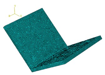
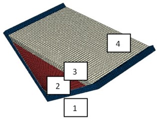
Fig. 4The mesh of V-shape plate with four layers of different materials
4. Finite element modeling
4.1. Model geometry
The ABAQUS software package is used to build and analyze the solid model and finite element mesh of the 120° V-shape plate. The V-shape plate shown in Fig. 3 is modeled taking advantage of symmetry, using 54716 linear tetrahedral elements of type C3D4. For the V-shape plate with different layers of materials 53332 linear tetrahedral elements of type C3D4 along with 31616 linear hexahedral elements of type C3D8R are used to model the plates (Fig. 4). The mesh is biased towards the center of the plate where the explosive is detonated and most deformation occurs. All degrees of freedom are fully constrained at the flat section of the plate to simulate the clamped boundary conditions.
4.2. Material properties of V-shape plate
The Johnson and Cook material model is used as shown in Eq. (1) [18]. The model describes the material flow stress as a function of strain, strain rate, and temperature. The model assumes the strength of the material is isotropic and independent of mean stress:
where is the yield stress at non zero strain rate, is the equivalent plastic strain, is the normalized equivalent plastic strain rate, is the material temperature (K) and is the melting temperature of the material. The constants are material dependent parameters and may be determined from an empirical fit of flow stress data. Table 1 lists the material dependent parameters used in the model [12]. For the plate with enforcement shown in Fig. 3, different materials are used as listed in Table 2. Balsa wood, honeycomb and aluminum-foam are well-known engineering structures which have been widely used in defense industry. Tables 3 and 4 show their material properties [17].
Table 1Material properties of the V-shape plate [11]
Specific heat (J/kgK) | (K) | (s-1) | (MPa) | (MPa) | |||
477 | 1 | 1793 | 1 | 0.014 | 0.987 | 1423 | 818 |
Table 2The studied cases
4 | 3 | 2 | 1 | |
Aluminum | Honycomb | Aluminum | steel | 1 |
Aluminum | Honycomb | Steel | steel | 2 |
Aluminum | Honycomb | Aluminum – foam | steel | 3 |
Aluminum | Balsa wood | Aluminum | steel | 4 |
Aluminum | Balsa wood | Steel | steel | 5 |
Aluminum | Balsa wood | Aluminum – foam | steel | 6 |
Aluminum | Aluminum – foam | Aluminum | steel | 7 |
Aluminum | Aluminum – foam | Steel | steel | 8 |
Aluminum | Aluminum – foam | Aluminum – foam | steel | 9 |
Table 3Isotropic properties of Balsa wood and Honeycomb [17]
(kg/m3) | (GPa) | (GPa) | (GPa) | (GPa) | (GPa) | (GPa) | Material | |||
600 | 0.01 | 0.01 | 0.36 | 0.2 | 0.2 | 0.059 | 1.355 | 0.054 | 0.054 | Balsa wood |
80 | 0.1 | 0.1 | 0.33 | 0.26 | 0.26 | 0.02 | 1.4 | 0.083 | 0.083 | Honeycomb |
Table 4Elastic properties of aluminum – foam [17]
(kg/m3) | (GPa) | (GPa) | Material | |
600 | 0 | 2.25 | 4.5 | Aluminum foam |
4.3. Properties of air
The air and post-burning gas product media are assumed to behave as an ideal gas. Hence, the default equations of state are used:
where are the specific heat at constant volume and pressure and the density of the gas respectively, whilst is the gas temperature. The air model is depicted in Table 5.
Table 5Air properties
(kJ/kgK) | (kJ/kgK) | (K) | (kg/m3) |
0.718 | 1.005 | 288.15 | 1.225 |
4.4. Modeling the blast
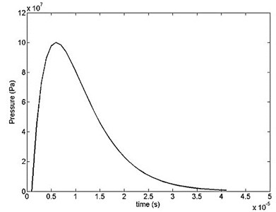
The incident pressure pulse is represented by the following function:
where is measured in µsec and in Pa (N/m2). Numerical values of the parameters in Eq. (5) are taken as: 5.436 MPa, 1, 1 µsec, 0.2 µsec-1 [17]. The shape of the pulse is illustrated in Fig. 5. The maximum pressure magnitude according to Eq. (6) is 100 MPa at 5 µsec.
Fig. 5Pressure-time variation for the blast pulse
5. Results and discussion
In this section, we compare the time variation of transverse displacement, von Mises stress, and principle stress and strain for the 120° V-shape plate with and without layered materials. These results will allow us to evaluate the blast mitigation ability of each case in comparison with the others. The objective is to minimize the transverse displacement and attenuate it through the thickness as much as possible. Fig. 6 presents a comparison of results for transverse displacement and illustrates how it varies through the thickness of each case. It is evident from Fig. 6 that case “7” shows the best performance whilst the worst one is case “3”. The backup layer (aluminum foam) makes its effect by reducing flexural deformation. In the “no core” case the displacement grows and reaches the maximum value of 2.5 mm at 30 µsec while it is 0.5 mm at the same time for the case “7”.
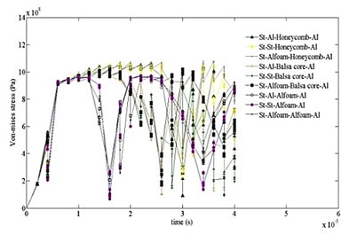
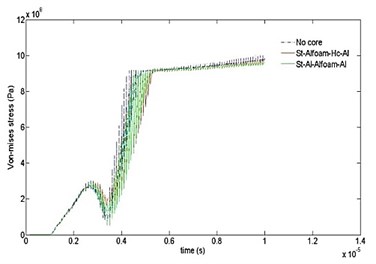
The results of comparison for von Mises stress variation with time is depicted in Fig. 7 for different cases. It can be observed that the highest values of stress start developing near the end of 4 µsec. Possibly this manifests the start of catastrophic failure of the V-shape plate. It is found that utilization of layers would undoubtedly survive the blast event. It is also seen that the effect of stress attenuation is considerably stronger in case “7”.
Fig. 6Time variations of displacement computed for ten cases
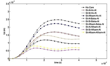
Fig. 7Time variation of von Mises stress computed for ten cases at different time intervals
a)
b)
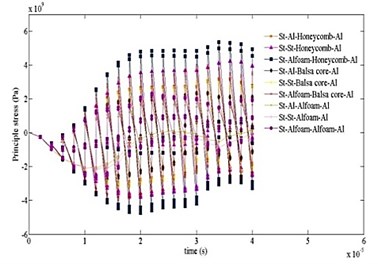
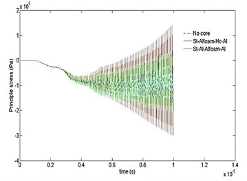
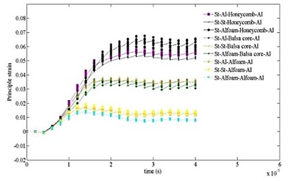
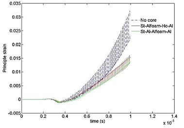
Figs. 8 and 9 show the comparative results of principle stress and strain with time for different cases. As can be seen, the highest values of stress and strain start developing near the end of 4 µsec as similar to Fig. 7. The peak values are significantly higher for “no core” case. It is also detected that the effect of stress and strain attenuation is significantly stronger in case “7”.
Fig. 8Time variation of principal stress computed for ten cases at different time intervals
a)
b)
Fig. 9Time variation of principal strain computed for ten cases at different time intervals
a)
b)
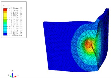
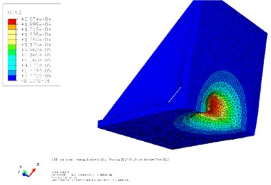
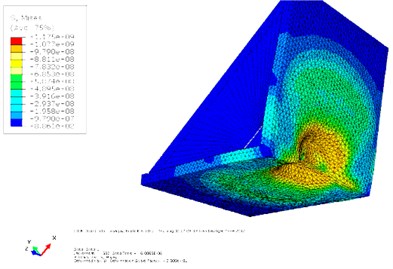
Figs. 10 and 11 show the contours of displacement and von Mises stress for the 120° V-shape plate of case “7” respectively. As can be observed, displacement is much lower in the case of using layers of materials which consequently leads to less damage to the vehicle and crew. Also, the von Mises stress values are much lower for the case “7” when compared to the case “no core”.
Fig. 10Contour of displacement for cases “7” and “no core”
a)
b)
Fig. 11Contour of Von Mises stress for cases “7” and “no core”
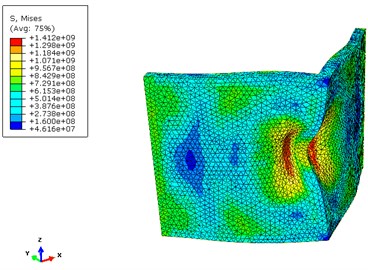
a)
b)
6. Conclusions
In this paper, finite element analysis of V-shape plates was conducted using ABAQUS. A comparative study was performed to enhance the resistance and energy absorption capabilities of V-shape plates. Various layers of materials such as metals, lightweight foams and Balsa wood were considered to identify the most efficient case. The results indicate that using honeycomb and Balsa wood had trivial effect on the blast mitigation of the V-shape plate, while usage of aluminum and aluminum foam yielded the desired results. Finally, it was concluded that the layers of materials should be used along with the V-shape hull to increase blast energy absorption and reduce injuries for the crew.
References
-
Mines Action Canada. Landmine Monitor Report 2011, Annual Report, Canada, 2011, p. 1-70.
-
Balos S., Grabulov V., Sidjanin L. Future armoured troop carrying vehicles. Defence Science Journal, Vol. 60, Issue 5, 2010, p. 483-490.
-
A study of mechanical application in demining. The Geneva International Centre for Humanitarian Demining (GICHD), Ch. 5, 2004, p. 121-148.
-
Ramasamy A., Hill A. M., Hepper A. E., et al. Blast mines: physics, injury mechanisms and vehicle protection. Journal of the Royal Army Medical Corps, Vol. 155, Issue 4, 2009, p. 258-264.
-
Kania E. Developmental tendency of landmine protection in vehicle. Modelling and Optimization of Physical Systems, Vol. 8, 2009, p. 67-72.
-
Nurick G. N., Lockley J. P. Experimental investigation to evaluate the effect of the included angle of a folded “V” shape plate for blast resistance. 1st International Conference on Integrity, Reliability and Failure, Porto, Portugal, 1999.
-
Genson K. Vehicle Shaping for Mine Blast Damage Reduction. M. Sc. Thesis, University of Maryland, College Park, 2006.
-
Benedetti R. Mitigation of Explosive Blast Effects on Vehicle Floorboard. M. Sc. Thesis, Department of Mechanical Engineering, University of Maryland, College Park, MD 20742, 2008, p. 1-127.
-
Anderson C. E., Behner T., Weiss C. E. Mine blast loading experiments. International Journal of Impact Engineering, Vol. 38, Issues 8-9, 2011, p. 697-706.
-
Gurumurthy G. Blast Mitigation Strategies for Vehicles using Shape Optimization Methods. M. Sc. Thesis, Massachusetts Institute of Technology, USA, 2008, p. 1-72.
-
Fairlie G., Bergeron D. Numerical simulation of mine blast loading on structures. 17th Military Aspects of Blast Symposium, 2002.
-
Yuen-Kim S. Ch., Langdon G. S., Nurick G. N., et al. Response of V-shape plates to localised blast load: experiments and numerical simulation. International Journal of Impact Engineering, Vol. 46, 2012, p. 97-109.
-
Baker W., Cox P., Westine P., Kulesz J., Strehlow R. Loading from Blast Waves. Explosion Hazards and Evaluation, Elsevier, 1983.
-
Slater J., Ritzel D., Thibault P. Development of computational methods and conduct of experimental tests for blast loading analysis. 3rd International Conference on Structures under Shock and Impact, Computational Mechanics Publications, Madrid, Spain, 1994.
-
Stansfield I. A paper on mine protection of military vehicles. Mine Warfare Committee, Rhodesian Army, Salisbury, Rhodesia, 1982.
-
Ramasamy A., Hill A. M., et al. Evaluating the effect of vehicle modification in reducing injuries from landmine blasts. An analysis of 2212 incidents and its application for humanitarian purposes. Accident Analysis and Prevention, Vol. 43, 2011, p. 1878-1886.
-
Uddin N. Blast Protection of Civil Infrastructures and Vehicles using Composites. Woodhead Publishing Limited, 2010.
-
Johnson G. R., Cook W. H. A constitutive model and data for metals subjected to large strain, high strain rates and high temperatures. Proceedings of the 7th Symposium on Ballistics, Hague, Netherlands, 1983, p. 541-548.
-
Makwana D. R., Laxminarayan K. Numerical simulation of an armoured vehicle to anti–vehicle mine blast to optimize the structural rigidity. Simulation Driven Innovation, 2011, p. 1-7.
About this article

