Abstract
In this work the analytical expression is derived on the basis of the variational method for the evaluation of angular stiffness characteristics of the spherical multilayered elastomeric package joint-hinge subjected to loading with hinge moment and hydrostatic pressure on the lateral surfaces. Joint-package consists of alternating metallic and thin elastomeric layers. Metallic plates-layers are assumed to be rigid. It is demonstrated that the hydrostatic pressure can both mitigate and "harden" the hinge angular stiffness characteristics depending on which side surface of the elastomeric layer it is applied. Obtained relationships allow solving problems of optimal design, operation and control program selection for compensating joints of this type.
1. Introduction
Rubber and rubberlike materials (elastomers) are widely used in many sectors of industry [2, 4, 7]. Physical properties of elastomers, as polymeric materials, are qualitatively different from traditional construction materials because of their ability to maintain large elasticity deformations and small volume compressibility under deformation [3, 6]. Reinforced elastomeric structures (laminated elastomeric) consist of a large number of alternating thin layers of rubber and reinforcing layers of other, much more rigid than rubber, material. The connection of elastomer with reinforcing layer is usually done by means of vulcanization or gluing. Multilayer elastomeric structures have a special place: their axial compression stiffness is by several orders greater than the shear stiffness [6, 7, 10]. These structures are used in machine building, shipbuilding, civil engineering, aviation and aerospace due to its unique mechanical properties. Multilayer elastomeric structures successfully replace traditional technical systems, such as bearing, joints, compensating devices, shock-absorbers because of its important advantages: improving of machine dynamics, vibration and noise reduction, low shear and compression stiffness ratio. In practice, the packages of thin layers rubber-metal elements of different shapes are used: flat, cylindrical, conical, and others (Fig. 1). Number of layers may be different (at least three). In many applications of multilayer elastomeric structures their stiffness characteristics – the relationship between external forces imposed on the package and its displacement under load – are of great practical consequence.
Fig. 1Examples of multilayer elastomeric structures
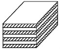
a) Rectangular
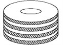
b) Ring
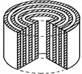
c) Cylindrical
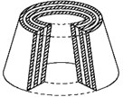
d) Conical
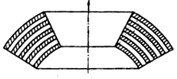
e) Spherical
This paper considers a stiffening behavior of spherical multilayer package joint-hinge with perfectly rigid metallic reinforcing layers under influence of hinge moment and hydrostatic pressure exerted on the free side of the package. Strength and stability of elements are regarded as ensured. Flexible laminated spherical hinges are used in rocket vehicle to provide the control of direction of thrust vector by means of movable nozzle. Of all the mechanical deflection types, the movable nozzles are the most efficient to thrust vector control system [9]. Example of an elastomeric spherical hinge application in rocket technology is given in Fig. 2.
Reinforced elastomers have been in use for more than 50 years. There are a large number of publications concerning this structure. The theory of the elastomeric layer is developed [7]; methodology of determination of stress and deformations are proposed; compression, shear and tilting stiffness for round, square and infinite-strip form are determined theoretically [1, 2, 11]. For thin spherical elements there is no theoretical basis and method of stiffness calculation in the case of side follower load taking into account orientation of side surface changing [8, 10].
2. Problem definition, analytical model and method of analytical solution
A flexible hinge made up of alternate spherical segments of elastomeric and rigid metal shims is considered. The behavior of elastomeric layers is only taken into account, assuming that the metallic layers geometry makes them perfectly rigid at this scheme of loading. The joint-hinge is loaded with hinge moment (in plane) and with simultaneous action of hydrostatic pressure and on the free lateral surfaces of elastomeric layers, respectively, on the internal surface () and outside one (). The purpose of this work is to obtain an analytical dependence for the angular stiffness characteristics of package-joint taking into consideration the influence of the pressure and on this characteristic. Loading scheme and the geometric parameters are shown in Fig. 3 in section of spherical coordinates , , .
Fig. 2Example of elastomeric hinge application
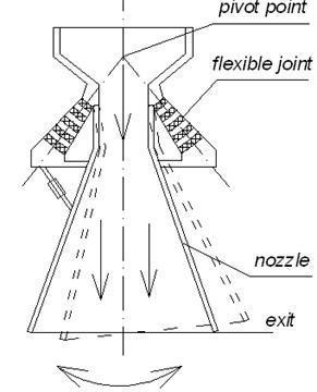
Fig. 3Object geometry and loading scheme at θ=0
Shear stiffness characteristics of joint-hinge are determined by means of Ritz's variation method using the linear theory of elasticity for an elastomeric material [6, 7]. At first, stiffness characteristic for one elastomeric layer is determined, i.e. joint with only one elastomeric layer is considered, then the package-joint response is studied.
2.1. Calculation of the stiffness characteristics of a single layer
The solution is carried out in two stages. Initially only hinge moment is imposed; loading and deformation scheme (in section ) is illustrated in Fig. 4. In the considered case the radial displacement and strains and are equal to zero. Geometrical boundary conditions for the displacement and (in the meridional and circumferential directions respectively) may be written as: if , and , if , and .
Functions, satisfying these conditions and to the expected character of deformation are:
Sought dependence “moment – rotation angle” is defined by means of the Ritz method from the total potential energy functional minimum condition [6]:
Obtained angular stiffness characteristic is:
where: .
Now the influence of pressure and , acting respectively on the free sides of the elastomeric layer at and isdetermined. First, the effect of the pressure is only taken into account with simultaneous action of hinge moment . The lateral surface of the elastomeric layer in an arbitrary section is considered (Fig. 5).
Fig. 4Loading and deformation scheme at θ=0
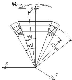
Fig. 5Deformation scheme in an arbitrary section
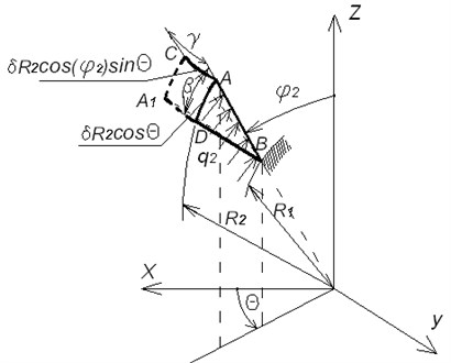
For thin elastomeric layers, even at small joint-hinge rotation angles reconfiguring of the elastomeric layers sides becomes significant. Since the pressure is follower load, which is always normal to the side surface of the elastomeric layer, significant change of its projections takes place relatively to the undeformed state of the elastomeric layer side. This leads to changing of the joint-hinge loading and must be taken into account in its analytical model. It is assumed that in view of the hinge geometry, its radial and flexural stiffness is significantly greater than the shear stiffness, i.e. radial and bending deformations, which can be induced by corresponding projections of pressure on the deformed surface, may be neglected. The elastomeric layer generator under the joint-hinge moment moves meridionally (on - direction) at the angle and in the circumferential direction at an angle and takes the position . Pressure remains normal to the deformed side of the elastomeric layer. Relative to the original surface vector of pressure can be decomposed into radial, circumferential and meridional direction components:
From Fig. 5: where
Hinge shear takes place in plane. To determine the effect of pressure on the angular stiffness of swivel joint, it is necessary to calculate the moment in plane as the results of pressure , acting on the lateral surface of the deformed elastomeric layer at :
As soon as
The integral (3) is not taken by elementary functions. Let us denote:
For the sufficiently thin elastomeric layers . Expanding the integrand in (3) into series relatively to and leaving the first three members, after integration we obtain:
From the equations (3) and (4):
Total angular hinge stiffness under the simultaneous action of hinge moment and pressure is defined from the condition of movable metallic layer equilibrium at in the plane of the hinge bending : From this expression the value of hinge moment , which provides a desired angle of hinge rotation at presence of the pressure , is defined:
If the pressure on the side surface of an elastomeric layer is imposed, considering the scheme discussed above for (at ) and taking into consideration the opposite signs of the corresponding direction cosine to the surface , we obtain the equation for the moment , ensuring predetermined hinge rotation angle :
Consequently, the imposed pressure leads to increase of control hinge moment for a given rotation angle providing, i.e. to “mitigation” of angle stiffness; the imposed pressure at leads to decrease of control joint-hinge moment for a desired rotation angle providing, i.e. “toughen” the angular stiffness. Finally, under the simultaneous action of the pressure and on both sides of the elastomeric layer the control joint-hinge moment is equal to:
2.2. Calculation of stiffness characteristics of the package joint-hinge
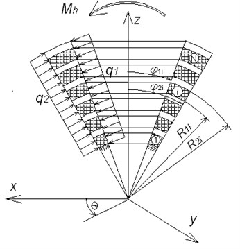
For estimation of the stiffness characteristics of the packaged–joint consisting of N elastomeric layers, all of the above calculations are repeated. Deriving of the corresponding equations for each elastomeric layer one should keep in mind, that in a multilayer joint the moments caused by pressure and are transferred (and accumulated) from layer to layer – from mobile top layer of the packaged hinge to fixed lower layer. The introduced denotements for arbitrary th layer are:
Then from expressions (7) and (8) for total packaged-joint we get a system of equations:
System (9) has equations and desired angular values , , ,…, , and allows to find: angles of rotation separately for each layer and total angle of packaged joint-hinge for a given , and ; hinge moment , which provides the desired behavior of package – hinge for the given rotating angle and pressure and value; pressure value and , providing the desired behavior mode when hinge moment and rotation angle of total hinge package are given.
Introducing the concept of the “middle” layer, from the system (9) for the sufficiently thin elastomeric layers the approximate, but sufficiently accurate analytical expression may be derived for the calculation of the angular packaged-joint stiffness for different combinations of values of , , , . For this purpose let us assume that all the elastomeric layers work as one “middle” layer, separated in the midsection of pack, the geometry of which is denoted as: , , , , , , , (where – the number of elastomeric layers in packaged joint). In this case, from the system (9) for the total angle of rotation of the packaged joint we have:
From the equations (8) - (10) the connection of control hinge moment with angle of rotation of all package hinge and pressure and is derived:
Here we consider small angles of joint rotation , which provide hinge deformation (angles ), for which the linear relationships between the angular deformation and shear stresses in the material of the elastomeric layers are still valid. For shear and torsion it is valid for deformation up to 40-50 %. This condition imposes a limit on the number of layers of elastomeric and at a given angle and a given elastomeric layer geometry.
Let us consider separately the metallic and elastomeric layers. For small angles of rotation on the surface of the metal layer , and , we calculate the moment about axis :
where the intensity of surface force on the metal layer for surface as the results of pressure is equal:
Then the equation (12) may be rewritten:
As it follows from (13), the presence of pressure does not influence joint shear provided that the metal layer is completely rigid (not deformable). It should be noted that for large angles of rotation , which lead to an essentially nonlinear angular deformities in the elastomeric layer packet hinge, this influence is not zero. This is due to the fact that surface loads , , on the metal layer at do not change since this metallic layer is not deformed, but arms vary: , .
3. Numerical examples and experiment results
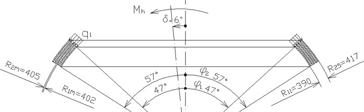
The example of theoretical calculation and results of experiment are given below for the multilayer joint-hinge with geometry: 390 mm, 417 mm, 3 mm, 3 mm, 5, 47°, 57°, 6° and shear modulus of the elastomeric layers 460 kPa (Fig. 6).
Fig. 6Testing packaged joint-hinge geometry
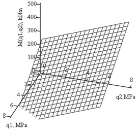
Theoretical calculations were performed in accordance with analytical expression (11), where the moment dependence on pressures and is linear due to small rotation angle and linear dependence between stress and strain. In Fig. 7 plots of joint-hinge moments dependence on hydrostatic side pressure and are shown for the simultaneous action of hinge moment and the pressure or (separetely (Fig. 7(a)) and together (Fig. 7(b)). In Fig. 8 plots of joint-hinge moments dependence on rotation angle and the hydrostatic side pressure and separately are presented.
Fig. 7Plots of joint - hinge moment Mh(kNm) dependence on the side pressures q1and q2 (MPa) for δ= 6°
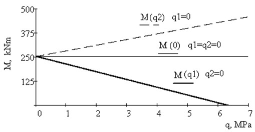
a),
b)
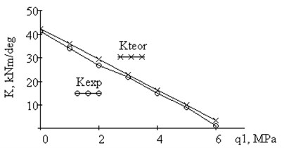
Experimental investigation of the stiffness characteristics of this joint were performed at the Moscow Institute of Thermal Technology. Testing was fulfilled under static rotation of joint with fixation of angle (Fig. 9). Because of the complexity of the experiment, only the pressure was applied to the inner surface side and integral characteristics “moment-rotation” were measured. In Fig. 10 plots of experimental and theoretical joint stiffness characteristics (kNm/deg) dependence on the hydrostatic side pressure are shown. Due to the fact that shear modulus of rubber sample and joint elastomeric layer are different, results of experiment and calculations somewhat differ. In multilayer joint of elastomeric layer may reach 490 kPa.
Dependence between and is linear to implement the requirements of constant deflection angle . Nonlinear dependence appears under simultaneous increasing of and .
The calculations indicate and experimental data confirm that for sufficiently thin elastomeric layers pressure and acting on the free sides of elastomeric layers essentially affects the angular stiffness characteristics of the hinge - package that must be taken into account both during design and operation of such class of joint-hinges for the considered type of loading.
Fig. 8Plots of joint - hinge moment Mh (kNm) dependence on the side pressures q1, q2(MPa) and rotation angle δ (rad)
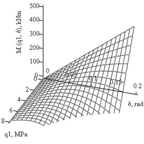
a)
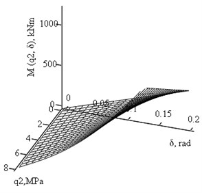
b)
Fig. 9Scheme of experimental setup
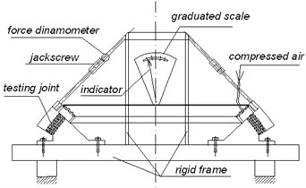
Fig. 10Plot of experimental and theoretical dependence of hinge rigidity on the side pressure q1
4. Conclusions
Analytical expression is derived on the basis of the variational method for estimation of angular stiffness characteristics of the spherical multilayer elastomeric package-joint during its loading with hinge moment and hydrostatic pressure on the lateral surfaces. The theoretical calculations are verified experimentally, which indicate that at the shear of spherical packaged- joint with rather thin elastomeric layers under the hinge moment the presence of hydrostatic pressure and , acting on the free sides of the elastomeric layers, influences the angular stiffness characteristics of the packaged hinge. The derived analytical expressions for the angular stiffness characteristics allow to take into account the effect of the above noted in the design and operation of this type of joints for the considered loading case. In the future research work it is planned to include the case of geometric nonlinearity.
References
-
Amin A. F. M. S., Lion A., Sekita S., Okui Y. Nonlinear dependence of viscosity in modeling the rate-dependent response of natural and high damping rubbers in compression and shear: experimental identification and numerical verification. International Journal of Plasticity, Elsevier, Vol. 22, 2006, p. 1610 1657, www.elsevier.com/locate/ijplas
-
Bauman J. T. Fatigue, Stress and Strain of Rubber Components: Guide for Design Engineers. Munich, Carl Hanser Verlag, 2008.
-
Frolov N. N., Moldovanov S. J., Lozovoy S. B. Mechanics of Thin Rubber Elements. Kuban State Technological University, Krasnodar, Publishing House “Jug”, 2011.
-
Gent A. N. Engineering with Rubber: How to Design Rubber Components. 2-nd Ed., Munich, Carl Hanser Verlag, 2001.
-
Kelly J. M., Konstantinidas D. A. Mechanics of Rubber Bearings for Seismic and Vibration Isolation. John Wiley & Sons, UK, 2011.
-
Lavendel E. E. Design Methods of Workpieces from Highly Elastic Materials. Riga, Zinatne, 1990.
-
Malkov V. M. Mechanics of Multilayered Elastomeric Structures. St-Petersburg, St.-Petersburg University Press, 1998.
-
Mtenga P. V. Elastomeric Bearing Pads under Combined Loading. Final Report, Contract No: BC352_16, 2007, www.dot.state.fl.u..._STR/FDOT_BC352_16_rpt.pdf
-
Pisacane V. L. Fundamentals of Space System. 2-nd Edition, Oxford University Press, 2005.
-
Semenenko V. P. Some tasks of performance of rubber joints. State Space Agency of Ukraine, Scientific and Technical Collection Space Technology, Missile Armament, Issue 1, 2012, p. 149 161.
-
Tsai H.-C. Flexure analysis of circular elastic layers bonded between rigid plates. International Journal of Solids and Structures, No. 40, 2003, p. 2975 2987.
About this article

This work has been supported by the ERDF’s Grant, within the project “SATTEH”, No. 2010/0189/2DP/2.1.1.2.0/10/APIA/VIAA/019, being implemented in Engineering Research Institute “Ventspils International Radio Astronomy Centre” of Ventspils University College (VIRAC).
