Abstract
IVUS (Intravascular Ultrasound) is a useful medical device to observe the thrombus in blood vessels, and such a micro motor less than 1.0 mm in outer diameter is desired to apply IVUS in narrow brain vessels. In our previous works, ultrasonic motor consisting of a wire coil type stator, a waveguide, a cylindrical rotor, an ultrasonic vibrator has been developed. This motor is rather easy to miniaturize because of its simple structure. However, this motor behavior is unstable rotate. To improve these problems, a foil type stator has been applied in stead of a wire coiled stator. An ultrasonic motor with 0.05 mm thick foil type stator was manufactured and tested their performances. It was able to verify that this ultrasonic motor with a foil type stator has the right quality. So, simplified IVUS system using ultrasonic motor with a foil type stator was manufactured and tested their fundamental performances. In order to expand development of new application, ultrasonic motor with a shortened waveguide and ultrasonic motor integrated driving unit with a stator was developed.
1. Introduction
Micro ultrasonic motor that uses a coiled waveguide and its driving performance is reported. The invented ultrasonic motor [1]has a simple structure and is easy to be miniaturized compared to existing ones. This ultrasonic motor consists of vibrator, rotor and waveguide. In the waveguide, there are two parts of the arm and the coil. The arm is thin wire, and one end of arm is a shape of the helical coil. The arm plays the role to propagate the ultrasonic vibration. The coil plays the role of stator. The rotor is supported with coil. Because of this structure, this ultrasonic motor is no need for a spring for preloading and any piezo-electric element at driving point. Therefore it is more suitable for micro ultrasonic motor. So, for a practical use of this motor, we are trying to apply it to a catheter for medical treatment. For the first trial, we apply it to the catheter used for a blood vessel thrombus. This motor is installed at the top of catheter and gives turbulence to the flow for stirring the thrombus dissolution medicine, it is thought more effective for thrombus treatment.
2. Driving principle and composition of motor
Driving principle of the motor is described. A feature in driving principle of this motor is to propagate the ultrasonic wave to coiled Stator. Moreover, the composition of the motor that dimension is 0.8 mm in diameter and 4 mm in length is described.
3. Driving principle
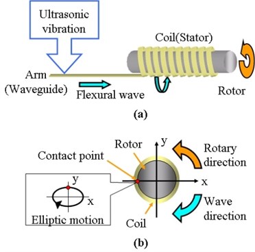
Driving principles are shown in Fig. 1. The motor is consisted by a coiled (stator) with arm and a rotor and a vibrator. The one end of arm is connected to an ultrasonic vibrator and supplied with ultrasonic vibration, and the other end is kept free as shown in Fig. 1a. Applied ultrasonic vibration induce flexural wave in an arm, and it becomes a traveling wave, and propagates in arm. Then traveling wave propagates to a coil, coil’s surface performs elliptic motion, and rotor performs rotational and transverse movement by frictional force which is generated by contacts between the rotor and the wave which propagates in coil as shown in Fig. 1b. At this time, frictional force works opposite direction of advance direction of traveling wave.
In Fig. 1a and Fig. 1b, rotor is arranged inside of coil, but motor can drive when coil is arranged inside of pipe type rotor.
Fig. 1Driving principle
4. Composition of motor
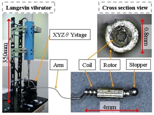
Figure 2 shows the composition of motor. The Langevin type vibrator is used for the wave transducer. The one end of arm is fixed on the stage set up under the vibrator, and pressed against the tip of vibrator. The flexural wave propagates in arm, and reaches to coil. The rotor which arranged outside is driven. To prevent the rotor from flying out from coil, a steel ball is bonded to the top of the coil. The dimension of the motor is 0.8 mm in diameter and 4.0 mm in length. The photograph in the upper right of Figure 2 is a cross section view of the rotor and the coil which steel ball is not bonded.
Fig. 2Composition of motor
5. Driving performance
It reports about the rotational speed when the preload that gives rotor is changed. Moreover, the torque calculated from the rotational angular speed is reported.
6. Change in rotational speed by preload
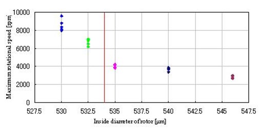
Preload that gives rotor is greatly related to driving performance. This motor’s preload is decided by the outside diameter of coil and inside diameter of rotor. Therefore, the rotational speed measurement was done by using the coil that outside diameter is 544 μm and the rotor that inside diameter is shown in Table 1 and outside diameter is 0.8mm. The rotational speed was measured by the digital tachometer (SANWA Co. Ltd., SE-100). Figure 3 shows the measurement result. The line in the figure shows the outside diameter of the coil. The rotational speed was faster when preload is given, and tended to rise by high preload.
Table 1Inside diameter of rotor
Rotor No. | 1 | 2 | 3 | 4 | 5 |
Inside diameter [μm] | 530 | 532.5 | 535 | 540 | 546 |
Fig. 3Rotational speed measurement of rotor with various inside diameters
7. Detailed measurement of rotational speed
The rotational speed of the motor was measured more in detail to calculate driving performance. Measurement system is shown in Fig. 4. The measurement method is described. The laser of the laser displacement sensor is irradiated to the teeth of the gear that is installed to the rotor. When the motor rotates, the displacement data of teeth of the gear is collected by the oscilloscope. The rotational speed is calculated from the time taken between the teeth and teeth. The torque is calculated from rotational angular acceleration at the rise time of the rotation speed. The measurement result of the rotation speed and the torque is shown in Figure 5. The used rotor is No. 1 in Table 1. From the N-T curve in the figure, start torque was about 0.2 μN m. This torque value is very small, so it should be made the most suitable preload.
8. Application to catheter medical treatment
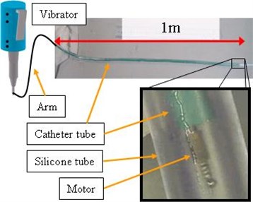
The application to the thrombus catheter treatment in the blood vessel is thought as a practical use idea of the motor. The thrombus in the blood vessel is treated by pouring the thrombus dissolution medicine from the catheter. The improvement of the therapeutic gain is expected by stirring the dissolution medicine by the motor. Figure 6 is the appearances of the examination for practical use. The catheter that attached the motor was inserted into the silicon tube of 3 mm in the diameter which the inside was filled with pseudo blood. As a result, the stir action by motor drive was confirmed. It will be thought that the examination in an environment that is nearer the human body is necessary in the future.
Fig. 4Measurement system

Fig. 5Detailed measurement of rotational speed
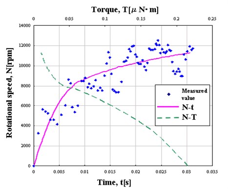
Fig. 6Driving test in pseudo blood
9. Conclusions
Driving performance of the motor and the application to the catheter treatment were examined. The driving performance improvement of the motor and the practical use examination in an environment near the human body is needed in the future.
References
-
Moriya T., Furukawa Y., Akano Y., Nakajima A. Experimental Study on a Miniature Ultrasonic Motor Using a Coiled Stator. IECEI Technical Report, No. US2005-29, July, 2005, (in Japanese).
About this article

