Abstract
This paper deals with the torsional waves propagating in a pipe contacting with viscous liquid. The expression describing the movement of viscous liquid near the pipe is presented. Both the pipe is filled with and immersed in the liquid are considered and both the isotropic and transversely isotropic pipes are investigated. Numerical calculations were carried out to investigate the influence of viscosity of liquid on the dispersion and attenuation curves. The first torsional wave mode is investigated individually by varying the viscosity and the density of the liquid. It is concluded that the viscosity of the liquid has little influence on the dispersion curves, while its main effect is the attenuation. When the frequency and the thickness of the pipe are not large, the attenuation ratio between the two cases of pipe immersed in liquid and pipe filled with liquid is approximately a constant, which is determined by the ratio of inner radius and the thickness.
1. Introduction
Corrosion in piping structure is a major problem in industry. Guided ultrasonic waves can be excited at one location on the pipe and propagate a long distance along the pipe. The wave are reflected from the corroded site and received by the sensors. However, since many pipes are buried in liquid, or may carry a liquid. There is a need to consider the wave propagation characteristics of pipes contacting with liquid.
A large body of work has contributed to our current understanding of cylindrical wave propagation. The dispersion curves for a hollow isotropic cylinder were treated by Gazis in 1959 [1]. Later Kumar (1971, 1972) [2, 3] examined the effect of liquid on wave propagation in cylinders. Leaky cylindrical systems have been much more difficult to model than their free counterparts. Much of the difficulty arises from the need to calculate complex Bessel functions. Safaai-Jazi et al. (1986) [4] derived the cutoff conditions for all modes in a fiber with infinitely thick cladding. Simmons et al. (1992) [5] investigated the axsymmetric modes in infinite clad rods. Viens et al. (1994) [6] solved the torsional wave in an infinite clad rod. Entire range of dispersion curve solutions was examined in these studies.
Nagy (1996) [7] hypothesized the viscous liquid as an isotropic solid by extending the analytical treatment of longitudinal wave propagation along the fiber immersed in a viscous liquid. Lafleur and Shields (1995) [8] studied the axisymmetric propagation of low frequency modes in a liquid-filled tube. Elvira-Segura (2000) [9] analyzed the case of a cylinder filled with a viscous liquid. Aristegui et al. (2001) [10] investigated the wave propagation characteristics of pipes with liquid loading on both the inside and outside of the pipe. Bllandras et al. (2006) [11] modeled damping effects of guided elastic waves at the interface between viscous liquids and a semi-infinite solid or plate.
In these researches, the longitudinal wave in cylinder was dealt with. The torsional mode of guided wave in cylinder was not investigated as much as the longitudinal mode. As expected, the longitudinal wave is sensitive to circumferential damage in the tube, but not sensitive to the damage in the axial direction; while in theory the torsional wave can detect these two types of damage. The propagation characteristic of torsional wave in various structures has been attracted much attention. Viens et al. (1994) [6] have studied the propagation characteristic of torsional mode in a rod with an infinite cladding theoretically. Demma et al. (2003) [12] have investigated the sensitivity of wave of mode in pipe to circumferential damage. Kwun et al. (2004) [13] have investigated the attenuation of torsional guided wave in coal-tar-enamel-coated buried pipes experimentally. It is found that the attenuation increases as the frequency increases. Ragulskis et al. (2006) [14] developed a numerical procedure for the analysis of non-Newtonian fluid flow in a longitudinally vibrating tube. A special modification of the harmonic balance procedure is proposed for this non-linear problem.
This paper describes an investigation of the torsional wave in pipe filled with or immersed in viscous liquid. A theory is presented to describe the motion in the viscous liquid near the pipe. The dispersion and attenuation curves are obtained and analyzed. The attenuation of the first torsional wave mode in different density and viscosity of the liquid, and in different thickness of the pipe is discussed.
2. Theory
A monochromatic acoustic wave propagating in an elastic tube, filled with viscous liquid, or in a tube immersed in viscous liquid, is considered. The wave equation for the solid and the liquid are studied separately, and then the equations describing the propagation through the two media are given by applying the boundary conditions. Only the harmonic torsional wave is considered.
2.1. Motion in the pipe
Following the theoretical analysis by Gazis (1959) [1] and Pavlakoivc (1998) [15], in an isotropic, elastic pipe, the motion and shear stress of torsional wave in cylinder are:
where and are constants, is the shear modulus, is the wavenumber in the direction, is circular frequency. and is a pair of linearly independent Bessel functions. . If there is attenuation in the wave, the wavenumber will be complex and the arguments of Bessel function q will be complex. Complex Bessel functions will need to be used for the calculation. However the same substitutions and as the real can still be used for internal layers to stabilize the solutions (Pavlakoivc 1998) [15].
2.2. Motion in the liquid
The torsional wave in the pipe has motion only in direction. Nonviscous liquid will not affect the propagation of torsional wave. As the pipe contacts with viscous liquid, the liquid will be drived by the force of viscosity. The movement of the viscous liquid caused by the torsional motion of the pipe is discussed below.
The liquid is supposed to be compressible, Newtonian and the body force is neglected, its initial velocity is zero. The propagation of a monochromatic acoustic wave in the liquid can be described as (Elvira-Segura 2000) [9]:
where and are the dynamic compressional and shear coefficients of viscosity, whose unit is Pa∙s. The relation between dynamic viscosity coefficient and the kinematic viscosity coefficient is . is the velocity vector in liquid, is the density of liquid. is the Hamilton operator. is the wavenumber in free liquid, .
Use Helmholtz decomposition, the velocity can be expressed as a sum of two components: a compressional scalar potential , and an equivoluminal vector potential :
Substituting this relation in Eq. (3), a set of two equations is obtained:
In the theory of boundary layer, the viscosity force is large compared to the mass force in the boundary layer near the solid wall, while in other region the effect of viscosity is small. It is supposed that in the thin layer of liquid near the wall of pipe the movement of liquid is following the motion of wall, they have the same form of movement:
In torsional wave, the displacement is free of and the circumferential order 0, the compressional scalar potential . Because only the torsional wave is investigated here, the fluid can be considered as incompressible.
From Eq. (5b), this equation can be:
where .
Substituting the components of vector potential to Eq. (6) it gives these equations:
Substituting Eq. (7c) to Eq. (7a), it transforms to:
The solution of this equation is:
where and are constants, .
From Eq. (7a) we can get:
and from Eq. (7b):
The velocity component in direction is (for coinsicenes the constants and are written as and ):
The stress component is:
Suppose the flow near the pipe is laminar, from the theory of fluid dynamics the flow can be separated to boundary layer and out flow region (Cebeci and Cousteix 2005) [16]. In the boundary layer the viscosity force is large and in the out flow region the effect of viscosity is small. The flow out of the boundary layer should be the initial flow in the liquid. So Eq. (12) and (13) are valid in the boundary layer.
The dimension of thickness of the boundary layer satisfies:
where is the characteristic length, which can be chosen as the amplitude of vibration, is the characteristic velocity, which is the mean velocity of vibration, .
, and the period satisfy that .
The dimension of thickness of the boundary layer is:
For a liquid of the property in Table 1, when the frequency is 1 kHz, 7.07×10⁻⁴ m and when the frequency is 300 kHz, 4.08×10⁻⁵ m. We can see that . Out of the boundary layer the influence of the viscosity would be small, while the propagation of shear wave mainly depends on the viscosity. The thickness boundary layer is too small compared to the radius of the pipe 0.1 m. It can illustrate that the influence of wave will decay quickly in direction.
3. Boundary conditions and dispersion equation
3.1. Pipe filled with viscous liquid
In this section, a pipe filled with viscous liquid is considered. As Fig. 1, the inner radius of pipe is , the outer radius of the pipe is and the thickness of the pipe is . The liquid is presented by . The velocity and stress in the inner wall of pipe should be continuous. The outer wall of the pipe is free.
The boundary conditions are:
The energy of the shear wave in liquid would dissipate as propagating. It is discussed before that the most part of energy of the wave in liquid is confined in a thin layer near the pipe, which means that the energy lost in liquid will be fast and there is no wave can reach the wall of pipe. The displacement and stress of this wave should be expressed by Hankel function processing. When the pipe is filled with liquid, the wave is propagating toward the core. means the primal Bessel function. means second kinds of Bessel functions:
Substituting Eq. (1), (2), (17) and (18) into the boundary conditions:
The determinate of this matrix should vanish, the simplified dispersion equation is:
Fig. 1An infinite long pipe filled with viscous liquid
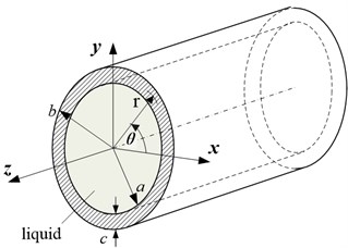
Fig. 2An infinite long pipe immersed in viscous liquid
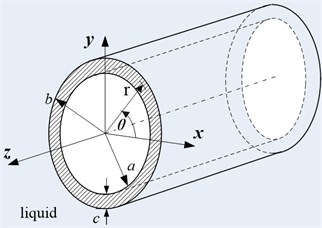
3.2. Pipe immersed in viscous liquid
In this case, the pipe is immersed in the liquid. The parameters of pipe and liquid are the same as the last section. The boundary conditions are:
Note that the energy of wave should decay quickly, there are only outgoing waves. The velocity and shear pressure in liquid are:
As Eq. (20), the dispersion equation is obtained by substituting the displacement and stress into boundary conditions:
4. Modes of torsional wave in pipe
Solving the dispersion equation in different frequency, the dispersion and attenuation curves can be plotted. Because of the viscous liquid the attenuation would always exists, the wavenumber is always complex. When solving the equations a Muller’s method algorithm of tracing the roots is employed. In dissipative media, the group velocity is not equal to the energy velocity, and the velocity of wave should be expressed by energy velocity (Bernard et al. 2001) [17]. The phase velocity, group velocity, energy velocity and attenuation are defined as following:
where is the average power in a period, is the total energy in a period, is the kinetic energy in a period, is the potential energy in a period, means th layer of the waveguide.
where is the napierian base, , is frequency, is the thickness of pipe.
4.1. Pipe filled with viscous liquid
The pipe carries viscous liquid in it, and is free on the surface outside. The material of the pipe is aluminum. The material properties are shown in Table 1. The inner radius of pipe 0.1 m, the outer radius of pipe 0.11 m, thickness is 0.01 m.
Table 1The material properties of the pipe and liquid
Shear modulus (Gpa) | Shear bulk wave velocity (m/s) | Dynamic viscosity coefficient (Pa∙s) | Density (kg/m3) | |
Pipe | 26.3 | 3122 | - | 2700 |
Liquid | - | - | 1 | 1000 |
Table 2Viscosity coefficient and density of some liquid
Liquid | Dynamic viscosity coefficient (Pa∙s) | Density (kg/m3) | Kinematic viscosity coefficient (m2/s) |
Chloroform | 5.6×10⁻⁴ | 1484 | 3.8×10⁻⁷ |
Water | 1.0×10⁻³ | 1000 | 1.0×10⁻⁶ |
Ethanol | 1.2×10⁻³ | 790 | 1.5×10⁻⁶ |
Florence oil | 0.1 | 909 | 1.1×10⁻⁴ |
Glycerin | 0.4 | 1261 | 3.2×10⁻⁴ |
Castor oil | 1.0 | 955 | 1.0×10⁻³ |
is the kinematic viscosity of the liquid.
The dispersion and attenuation curves of first six modes of torsional wave are shown below. In this case a large viscosity of 1 Pa∙s is chosen.
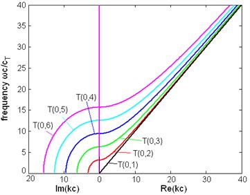
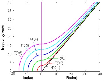
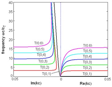
Fig. 3The dispersion relation between frequency and wavenumber of first six modes of torsional wave in a pipe filled with liquid (η= 1 Pa∙s) and a free pipe: a) the dispersion relation of a pipe filled with liquid, b) the dispersion relation of a free pipe
a)
b)
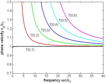
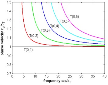
Fig. 4The normalized phase velocity of first six modes of torsional wave in a pipe filled with liquid (η= 1 Pa∙s) and a free pipe: a) the phase velocity of a pipe filled with liquid, b) the phase velocity of a free pipe
a)
b)
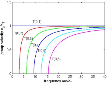
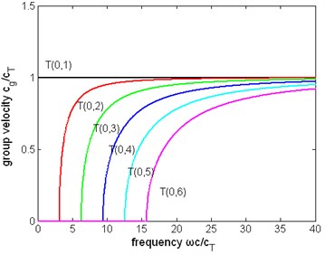
Fig. 5The normalized group velocity of first six modes of torsional wave in a pipe filled with liquid (η= 1 Pa∙s) and a free pipe: a) the group velocity of a pipe filled with liquid, b) the group velocity of a free pipe
a)
b)
Fig. 6The normalized energy velocity of first six modes of torsional wave in a pipe filled with liquid (η= 1 Pa∙s) and a free pipe: a) the energy velocity of a pipe filled with liquid, b) the energy velocity of a free pipe
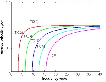
a)
b)
Fig. 7The normalized attenuation of first six modes of torsional wave in a pipe filled with liquid (η= 1 Pa∙s) and a free pipe: a), b) the attenuation of a pipe filled with liquid, c) the attenuation of a free pipe
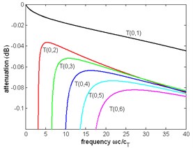
a)
b)
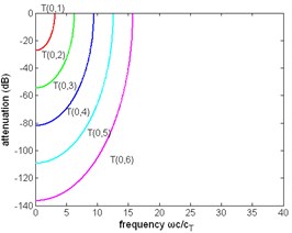
c)
4.2. Pipe immersed in viscous liquid
In this case, the material properties of all medium and the size of the pipe are the same with the case in last section, but the pipe is immersed in liquid. Also, the dispersion and attenuation curves of first six modes of torsional wave are presented.
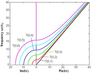
Fig. 8The dispersion relation between frequency and wavenumber of first six modes of torsional wave in a pipe immersed in liquid (η= 1 Pa∙s)
a)
b)
Fig. 9The normalized phase velocity of first six modes of torsional wave in a pipe immersed in liquid (η= 1 Pa∙s)
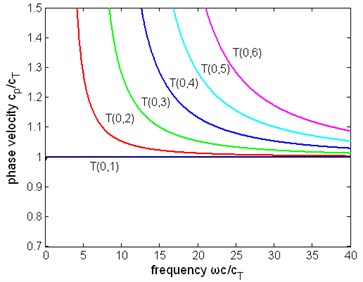
Fig. 10The normalized group velocity of first six modes of torsional wave in a pipe immersed in liquid (η= 1 Pa∙s)
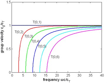
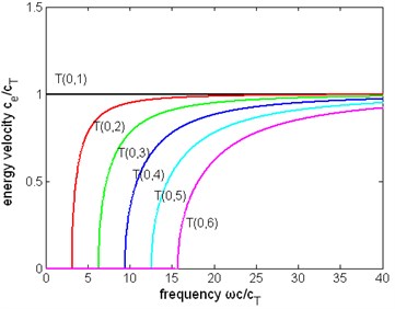
Fig. 11The normalized energy velocity of first six modes of torsional wave in a pipe immersed in liquid (η= 1 Pa∙s)
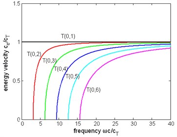
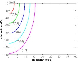
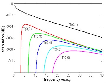
Fig. 12The normalized attenuation of first six modes of torsional wave in a pipe immersed in liquid (η= 1 Pa∙s)
4.3. The discussion of the results
The dispersion relation. When the pipe contacts with viscous liquid, the liquid is driven by the movement of pipe, and the energy is leaking into the liquid. So, there will be attenuation in the wave, the wavenumber is complex. From Fig. 3(a) and (c) we can see that the dispersion relation of the modes are close to that of a free pipe, but it can be seen in Fig. 3(b) that the wavenumbers are different when they are not large. The wavenumber of pipe with liquid is always complex, although its imaginary part in high frequency is small. From the right side of Fig. 3(b) the real part of the wavenumber approaches 0 when the frequency decreases to 0, not end in a non-zero frequency like the wavenumber of a free pipe. The same conclusions are obtained from Fig. 8.
Cutoff frequencies. From Fig. 3(c) the torsional modes in a free pipe have a cutoff frequency at which the wavenumber turns from real to imaginary, which means this mode stops propagating. Exactly speaking, this concept of cutoff does not exist in a pipe with liquid, for the wavenumber does not experience this change. However in a special frequency the real part of the wavenumber would decrease rapidly to a small value and in the same time the imaginary part increase abruptly. Although the real part of the wavenumber is not exactly 0, the wave is almost not propagating and the group, energy velocities are very close to zero. Another difference between the pipe with liquid and free pipe is there is not an exact frequency which can be called cutoff frequency, because from Fig. 3(a), (b) we can see that both the real part and the imaginary part of the wavenumber change continuously and there is not a special point where a sudden change of wavenumber happens.
Other dispersion curves. From Figs. 4, 5, 6 the velocity dispersion curves are similar to those of a free pipe, except that the curves of the first torsional wave mode is a little dispersive with frequency, while the first torsional wave mode in free pipe is not dispersive. It is one of the effects of viscous liquid. The group and energy velocity show not any significant difference. Fig. 7, 12 shows that first six modes of torsional wave all have attenuation which increases with frequency. Except the first torsional mode, the attenuation of a lower mode increases more quickly than higher modes. From Fig. 9, 10, 11, we can find that these velocity curves here have not any difference with the case of pipe filled with viscous liquid.
Difference between two cases of pipe. The phase, group and energy velocity of the two cases above do not show any difference, but the attenuation of these two cases is different. Comparing Fig. 7 with Fig. 12, it is found that the curves in these two figures have the same trend, and the ratio of magnitude of the attenuation of the first torsional wave mode in two cases is about 3/4, but the attenuation of higher modes of these two cases is almost the same. The curves of wavenumber of Fig. 8(b) are similar to Fig. 3(b), except for the imaginary part of wave.
4.4. The displacement distribution of the torsional wave
Fig. 13 is the normalized displacement along the radius of the pipe filled with viscous liquid, the frequency is 300 kHz. Only the first four modes are given. Fig. 14 is the same curves for a pipe immersed in liquid. As shown in these figures, the mode has displacement in all the thickness of the pipe, and the displacement of higher modes has some zero points.
Fig. 13The displacement distribution (normalized displacement: uθr/uθmax-uθmin) of the torsional wave of a pipe filled with liquid, f= 300 kHz, η= 1 Pa∙s
In these points there is not any displacement and if there is damage this mode of wave can not detect it, or has a reduced possibility to find it. From last two sections, the first torsional wave mode does not have a cutoff frequency, and it has a lowest dispersion. Its group and energy velocity are higher than other modes, which means the signal of this mode can be easily separated from other modes. These are all advantages of the first torsional wave mode in damage detection. The propagation of the first torsional wave mode should be investigated.
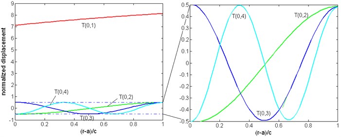
Fig. 14The displacement distribution (normalized displacement: uθr/uθmax-uθmin) of the torsional wave of a pipe immersed in liquid, f= 300 kHz, η= 1 Pa∙s
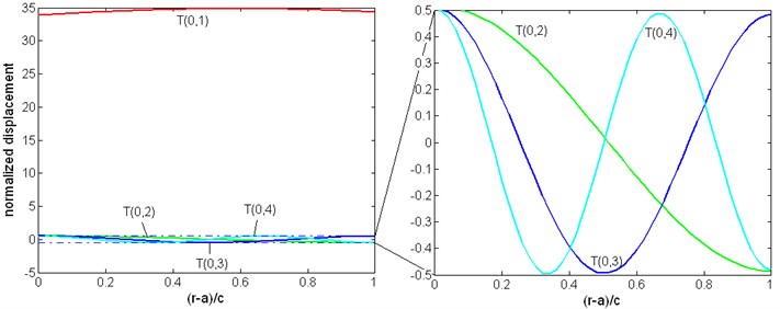
In free pipe, the displacement of the first torsional wave mode should be in direct proportion with radius: . But in Fig. 13, 14 the displacement in the side contacting with liquid is reduced. The wave structures of other modes have not any obvious change.
5. The influence of several parameters to the first torsional wave mode
5.1. The influence of viscosity to the first torsional wave mode
In order to investigate the effect of viscosity to the first torsional wave mode, the dispersion curves and attenuation curves in different dynamic viscosity coefficient are compared. Because the dispersion curves of phase, group and energy velocity change too small to measure, only the curves of phase velocity are given to illustrate this phenomenon.
Fig. 15The normalized phase velocity of the first torsional wave mode with liquid of different viscosity
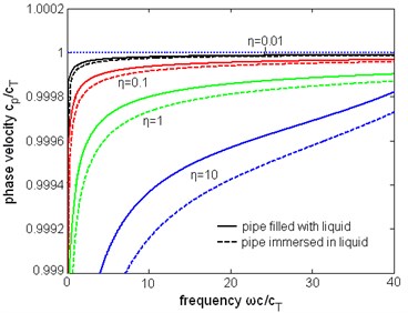
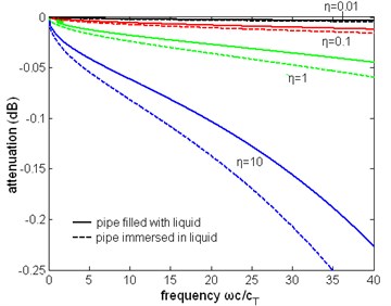
Fig. 16The normalized attenuation of the first torsional wave mode with liquid of different viscosity
Torsional wave has only displacement in direction, when the liquid is viscous the shear wave will leak into the liquid. The dispersion and attenuation of torsional wave are caused by this shear stress, which is determined by the viscosity of liquid. From Eq. (12), (13) it is concluded that the amplitude of velocity and stress should be in direct ratio with the frequency.
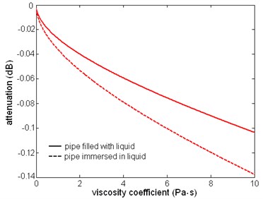
As shown in Fig. 15, the phase velocity of the first torsional wave mode changes with viscosity and frequency, but the change is small: as the dynamic viscosity coefficient increases from 0.01 to 10 Pa∙s, the difference is several m/s, which is hard to measure in practice. The main effect of viscous liquid is the attenuation of wave. From Fig. 16 it is obvious that the attenuation is increasing monotonically with viscosity and frequency. When the frequency and viscosity is not too high the curves are close to parabolic curves. When the pipe is immersed in the pipe the attenuation is larger than that when pipe is filled with the liquid. As in Fig. 17, these two curves are close to parabolic curves, the attenuation is in direct ratio with the square root of viscosity approximately. In the same frequency and viscosity the ratio of the attenuation of two cases is about 3/4.
Fig. 17The relation between attenuation and dynamic viscosity coefficient of the first torsional wave mode, f= 1 MHz
5.2. The influence of liquid density to the first torsional wave mode
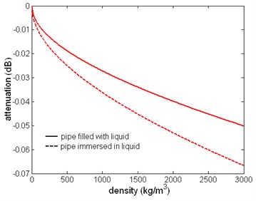
Fix the dynamic viscosity coefficient to 1 Pa∙s, the dispersion and attenuation curves in different liquid density are presented. From Fig. 18 the variation of liquid density has a small influence on the phase velocity. But the manner that density variation affects the dispersion curve is different. As the density increases, the shape of dispersion curve changes few. From Fig. 19, the change of attenuation caused by variation of density is quite flat. Fig. 20 is the relation between attenuation and the density. The curves are also parabolic approximately. It can be found that the ratio of these two values of attenuation remains a constant of about 3/4.
Fig. 18The normalized phase velocity of the first torsional wave mode with different liquid density, the unit of density is kg/m3
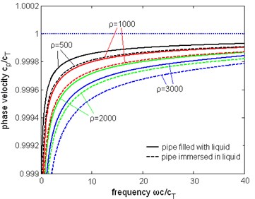
Fig. 19The normalized attenuation of the first torsional wave mode with different liquid density, the unit of density is kg/m3
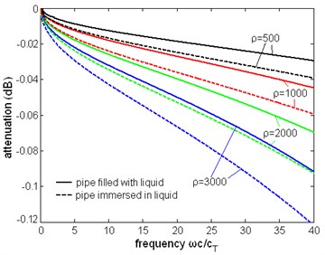
Fig. 20The relation between attenuation of the first torsional wave mode and liquid density, f= 1 MHz
5.3. The attenuation of the first torsional wave mode between pipe is immersed in liquid and pipe is filled with liquid
In the sections before it is found that the ratio of attenuation of two cases (when the pipe is filled with the liquid and when the pipe is immersed in the liquid) is a constant which is independent of viscosity and density. In the frequency 1 MHz, this ratio is about 3/4.
Fig. 21The attenuation ratio of two cases: pipe is immersed in liquid, pipe is filled with liquid. The inner radius of the pipe a= 0.1 m, the thickness is c, and η= 1 Pa∙s
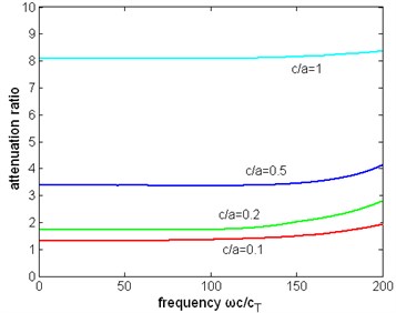
Fig. 22The attenuation ratio of two cases: pipe is immersed in liquid, pipe is filled with liquid. The proportion of inner radius and thickness c/a= 0.1, the thickness is c, and η= 1 Pa∙s
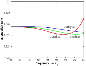
Fig. 21 shows that when the frequency and thickness of pipe is not large (about 100), the ratio of attenuation is approximately a constant which is depending on the thickness of the pipe. In the frequency range 0-2 MHz, the ratio of attenuation with the thickness 0.01 m changes about 1/1000. When the frequency and the thickness is large enough this ratio begins to rise.
Actually the ratio of attenuation of two cases is not determined by the thickness of the pipe, but by the proportion of radius and thickness. In different radius, the same proportion of radius and thickness can also leads to the same ratio of attenuation. But this conclusion is affected by the thickness of pipe and frequency. As Fig. 22, when the normalized frequency reaches 40, the ratio will vary obviously with the frequency and thickness.
6. Conclusion
This paper deals with the propagation properties of torsional wave in a pipe contacting with viscous liquid. By modeling the viscous fluids by the linear Navier-Stokes equation, the expression describing the movement of viscous liquid near the pipe is presented. The dispersion and attenuation curves are obtained and analyzed. The influence of several factors to the first torsional wave mode in investigated. It is concluded that the viscous liquid affects the dispersion property little, but causes much attenuation. The variation of viscosity and density have rather influence on the attenuation of the first torsional wave mode. When the frequency and viscosity is not large the attenuation is in direct ratio with the square root of viscosity and density approximately. When the frequency and pipe thickness is small, the attenuation ratio between the pipe is immersed in and filled with the liquid is a constant, which depends on the ratio of inner ratio and thickness of the pipe.
References
-
Gazis D. C. Three-dimensional investigation of the propagation of waves in hollow circular cylinders. Analytical foundation. Journal of Acoustical Society of America, Vol. 3, Issue 5, 1959, p. 568-573.
-
Kumar R. Flexural vibrations of liquid-filled circular cylindrical shells. Acoustica, Vol. 24, 1971, p. 137-146.
-
Kumar R. Dispersion of axially symmetric waves in empty and liquid-filled cylindrical shells. Acoustica, Vol. 27, Issue 6, 1972, p. 317-329.
-
Safaai-Jaz A., Jen I. C.-K., Farnell G. Cutoff conditions in an acoustic fiber with infinitely thick cladding. IEEE Transactions on Ultrasonics, Ferroelectrics and Frequency Control, UFFC-33, Vol. 1, 1986, p. 69-73.
-
Simmons J., Drescher-Krasicka E., Wadily H. Leaky axisymmetric modes in infinite clad rods. Journal of Acoustical Society of America, Vol. 92, Issue 2, 1992, p. 1061-1090.
-
Viens M., Tshukahara Y., Jen C., Cheeke I. Leaky torsional modes in infinite clad rods. Journal of Acoustical Society of America, Vol. 95, Issue 2, 1994, p. 701-707.
-
Nagy P. B., Nayfeh A. H. Viscosity-induced attenuation of longitudinal guided waves in liquid-loaded rods. Journal of Acoustical Society of America, Vol. 100, Issue 3, 1996, p. 1501-1508.
-
Lafleur L. D., Shields F. D. Low frequency propagation modes in a liquid-filled elastic tube wave-guide. Journal of Acoustical Society of America, Vol. 97, 1995, p. 1435-1445.
-
Elvira-Segura L. Acoustic wave dispersion in a cylindrical elastic tube filled with a viscous liquid. Ultrasonics, Vol. 37, 2000, p. 537-547.
-
Aristegui C., Lowe M. J. S., Cawley P. Guided waves in liquid-filled pipes surrounded by different liquids. Ultrasonics, Vol. 39, 2001, p. 367-375.
-
Ballandras S., Reinhardt A., Khelif A., Wilm M., Laude V., Daniau W., Blondeau-Patissier V. Theoretical analysis of damping effects of guided elastic waves at solid/liquid interfaces. Journal of Applied Physics, Vol. 99, 2006, p. 054907.
-
Demma A., Cawley P., Lowe M. J. S. The reflection of the fundamental torsional mode from cracks and notches in pipes. Journal of Acoustical Society of America, Vol. 114, Issue 2, 2003, p. 611-625.
-
Kwun H., Kima S. Y., Choib M. S. Torsional guided wave attenuation in coal-tar-enamel-coated, buried piping. NDT&E International, Vol. 37, 2004, p. 663-665.
-
Ragulskis M., Fedaravicius A., Ragulskis K. Harmonic balance method for FEM analysis of fluid flow in a vibrating pipe. Communications in Numerical Methods in Engineering, Vol. 22, Issue 5, 2006, p. 347-356.
-
Pavlakoivc B. N. Leaky Guided Ultrasonic Waves in NDT. Ph. D. Thesis, Imperial College, University of London, UK, 1998.
-
Cebeci T., Cousteix J. Modeling and Computation of Boundary-Layer Flows. Horizons Publishing Inc., Long Beach, 2005.
-
Bernard A., Lowe M. J. S., Deschamps M. Guided waves energy velocity in absorbing and non-absorbing plates. Journal of Acoustical Society of America, Vol. 110, Issue 1, 2001, p. 186-196.
About this article

