Abstract
The hydraulic damper has a great sense for impact machine to extend life and improve the environmental performance. The objective of this paper is to provide a systematic investigation to design or evaluation of a hydraulic damper used in the impact machine. A novel hydraulic damper using guiding sleeve to enlarge buffer chamber area is designed and manufactured by ingenious tactics. The performance of a prototype hydraulic damper is acquired by the test. A nonlinear thermal-hydraulic model for the hydraulic damper is presented by analyzing the internal fluid dynamic phenomenon and heat transfer with respect to the prototype. Comparisons between test data and simulation result confirm the validity of the thermal-hydraulic model. In the meantime, evaluation of the importance of some key factors using the model for designing is discussed. It shows the influence of orifice diameter, inner diameter of buffer chamber and setting pressure of the relief valve to hydraulic damper characteristics with large flow, which gives a theoretical basis to design and optimize hydraulic damper with large flow for impact machine.
1. Introduction
The impact cylinder with large flow is used commonly in fields of rock drilling, pile driving and forging. In working process of impact cylinders, the piston often strikes the cylinder cover with high speed, which produces a great impact force [1-3]. In order to avoid the piston strike the cylinder cover causing the damage to cylinder and equipment, a hydraulic damper is often set on the end of the stroke, so that the piston can stop moving smoothly without rebound.
At home and abroad, the study on hydraulic damper is mainly focus on vehicle damper. Tan [4] analyzed shortcomings of measuring experiment for hydraulic damper, and presented a new experiment scheme making damping characteristics for hydraulic damper measured accurately and simply; Wang [5] established fluid formula for changeable damping characteristics of two commercial railway semi-active hydraulic dampers, and presented damping changeability design; Duym [6-7] investigated the problem of heat transfer for hydraulic damper, and proposed modelling method using heat transfer; Samantaray [8] established a thermal-hydraulic model for a preloaded liquid spring damper shock absorber using bond graph; Jiao [9] developed a mathematical model for the hydraulic damper, and analyzed the effects of structure parameters to shock waves. However, the object of these studies is hydraulic dampers using in vehicle. Little research of a hydraulic damper with large flow to impact machine is done.
The piston in the impact machine is a high weight component with high speed. In order to decrease pressure impact in high speed, the hydraulic damper with large flow used in the impact machine often adopts throttle buffer in cylinder combining with the control of the relief valve outside the cylinder. In order to acquire the characteristics of the hydraulic damper with large flow applied widely in impact machine, the dynamic mathematic model of the hydraulic damper is established using fluid dynamics and thermodynamics theory [10] and also the simulation model using Simulink. Then, the influence of orifice diameter, inner diameter of buffer chamber and setting pressure of the relief valve to hydraulic damper characteristics with large flow is analyzed, which gives a theoretical basis to design and optimize hydraulic damper with large flow for impact machine.
2. Description of the novel hydraulic damper with large flow
Hydraulic damper with large flow sets on the end of stroke. It is composed by the guide sleeve, spring, oil joint, stopper, floating piston, check valve, relief valve and so on, which is shown in Fig. 1(a). In order to make damper device produce certain damping force, the buffer chamber area should be ensured in a specified range. The guid sleeve makes buffer chamber area break through the structure limits. One end of the spring is fixed on an annular slot in the guide sleeve, and the other end of the stopper. Two check valves are designed on a floating piston. In the initial status, the floating piston contacts with cylinder jacket under a compression force of the spring. Buffer chamber connects chamber of rod in the cylinder through two check valves and the relief valve. Pressure oil can flow into the buffer chamber through the check valves [11-12].
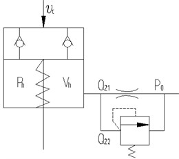
High pressure oil in the buffer chamber can flow into chamber of rod in the cylinder through the relief valve or the oil joint. The mechanic model of the hydraulic damper is shown in Fig. 1(b). The hydraulic damper absorbs impact energy to avoid the breakage of the cylinder when the piston of impact cylinder strikes on floating piston. The floating piston compress the buffer chamber, and the increased pressure in buffer chamber flow into tank, which makes the impact energy absorbed by orifice in the oil joint. If the pressure in the buffer chamber achieves the set pressure of the relief valve, the relief valve is opened to protect the buffer chamber.
Fig. 1Structure and mechanical model of hydraulic damper
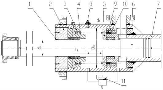
1 – dust seal, 2 – cylinder cover, 3 – guide sleeve, 4 – spring,
b) Mechanical model
3. Experimental results of the working characteristics of the hydraulic damper
3.1. Experimental set-up
The hydraulic damper is set on the end of the impact cylinder of ZCY hydraulic pile hammer, and Fig. 2 shows the experimental set-up. The impact cylinder is a single-piston-rod. The upper chamber is filled with nitrogen and the lower chamber is connecting to a hydraulic control system. In the initial condition, the volume of the chamber is , 0.06 m3, the nitrogen pressure in the chamber is , 1.7 MPa. In the test, impact velocity is measured indirectly through pressure measurement of nitrogen chamber [13]. The pressure and temperature in the hydraulic damper are acquired through the temperature and pressure integrated sensor.
Fig. 2Experimental set-up for dynamic testing
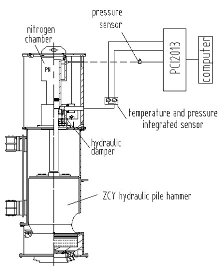
Fig. 3Test results of performances for hydraulic damper
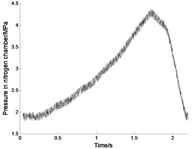
a) Pressure in nitrogen chamber
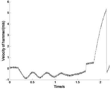
b) Impact velocity of hammer
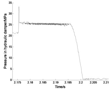
c) Pressure in hydraulic damper
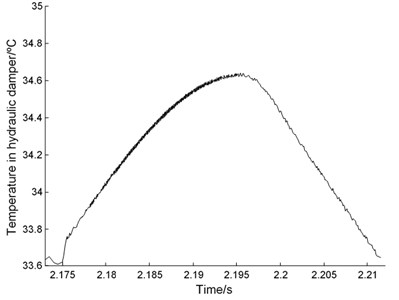
d) Temperature in hydraulic damper
3.2. Performance of the hydraulic damper
In the dynamic test, the pressure of hydraulic system is set to 21 MPa, which can ensure the working of the hammer. The measurement is started by making hydraulic pile hammer working without pile, which causes the hydraulic damper to absorb the impact energy. Fig. 3 illustrates the performance of the hydraulic damper. The max terminate velocity of the impact cylinder is almost to 5.73 m/s. The impact cylinder stroke on the hydraulic damper at 2.176 s, and the max pressure in the hydraulic damper reached to 33.7 MPa. The pressure in the hydraulic damper began to decline at about 2.196 s in the end of the cushion process. In this process, the highest temperature of oil in the damper reached to 34.65 ºC increased nearly 1 ºC. Therefore, the hydraulic damper to complete the process of energy absorption takes about 20 ms, far less than the working cycle of a pile hammer, which can meet the requirements of pile hammer to buffer mechanism. The change of temperature in the damper is very big, which would decline the performance of the damper. In analysis of performance for the hydraulic damper, it is necessary to consider the influence of temperature based on thermodynamics. In Fig. 3, all graphs are contaminated with noise. The source of noise may be the sensors and the measurement system, or the structure itself. In the static tests, the system pressure is set to 5 MPa which can not make the hammer move upward, the signals of pressure and temperature collected are held on constant values. However, there is a vibration of the structure in the working process of impact, which makes the connecting leads vibrate. The vibration of the leads results in the variation of the junction resistance of terminal, which make the noise which appeared in the collection. Hence, the noise is mainly caused by the structural vibration.
4. Thermal-hydraulic modelling of the hydraulic damper with large flow
4.1. Mathematics model of the hydraulic damper with large flow
(1) Thermal-hydraulic model for buffer chamber
The mass of liquid in the chamber is given by:
where is the mass of liquid in the chamber, kg; is the fluid density, kg/m3; and is the volume of the chamber, m3.
Considering the effect of temperature, the differential of buffer chamber pressure is given as Eq. (2):
where is the buffer chamber pressure, Pa; is the temperature of the buffer chamber, K.
Using the definition of the isothermal bulk modulus and cubical expansion coefficient, we can get:
Combining Eq. (2) gives:
where is the rate of pressure in the buffer chamber, Pa/s; is the rate of liquid density in the buffer chamber, kg/(m3s); is the rate of temperature in the buffer chamber, K/s.
Using the flow continuity equation, we can get:
where is the rate of liquid mass in buffer chamber, kg/s; is the rate of liquid mass flowing into buffer chamber, kg/s; is the rate of liquid mass flowing out of buffer chamber, kg/s.
Combing Eq. (4), the rate of pressure in the buffer chamber is given as follows:
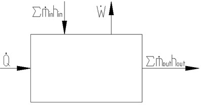
The liquid model in buffer chamber is shown in Fig. 4. The kinetic and potential energy for one-dimensional flow of fluid is very little, which can be ignored. Therefore, the corresponding ordinary differential equation for fluid energy in buffer chamber is:
where is the heat flowing into liquid in buffer chamber from outside, J; is the liquid energy in buffer chamber, J; is the work except for the work required to push mass into and out of the buffer chamber, J; is the enthalpy on inlet of buffer chamber, J/kg; is the enthalpy on outlet of buffer chamber, J/kg; the dot over a symbol is used to indicate time rate of change.
Fig. 4Liquid model in buffer chamber
The liquid energy in buffer chamber is calculated by:
where is the mass of liquid in buffer chamber, kg; is the special internal energy, J/kg.
The enthalpy is defined as:
where is liquid enthalpy, J/kg; is the liquid pressure, Pa; is the liquid density, kg/m3.
Since the liquids in cushion do not change phase, the specific enthalpy can be expressed as a function of temperature and pressure , that is . So the time derivative of can be expressed as:
The first term in Eq. (10) is recognized as the specific heat at constant pressure :
Combining Eq. (2), Eq. (3) and Eq. (10), gives:
Combining Eq. (7) gives:
where is the rate of volume in the buffer chamber, m3/s; is the rate of liquid mass in the buffer chamber, kg/s.
Combining Eq. (5) and Eq. (7) gives:
where , is shaft work, and is boundary work, and the dot over a symbol is used to indicate time rate of change.
Therefore, we can get:
Since the enthalpy on inlet and outlet of the buffer chamber is the same [14-16], the Eq. (15) can be simplified as follows:
(2) Model of relief valve and throttle hole
According to flow continuity equation, the flux through the relief valve is calculated by:
where is the flow coefficient of the relief valve; is the flow area of the relief valve, m2; is the liquid density, kg/m3; is the pressure in the buffer chamber, Pa; is the return oil pressure, Pa.
The waste energy through the relief valve can be calculated as follows by the energy equation:
where is waste power through relief valve, W; is the pressure in the buffer chamber, Pa; is the return oil pressure, Pa; is the flux through the relief valve, m3/s.
The flux flowing through throttle hole with thin-wall is calculated by:
where is the flow coefficient of throttle hole; is diameter of throttle hole, m; is the liquid density, kg/m3; is the pressure in the buffer chamber, Pa; is the return oil pressure, Pa.
According to energy equation, the waste energy through throttle hole is given by:
where is waste power through throttle hole, W; is the pressure in the buffer chamber, Pa; is the return oil pressure, Pa; is the flux through throttle hole, m3/s.
(3) Model of floating piston movement
The mass of hammer is so greater than the floating piston that the mass of floating piston can be ignored. The movement equation of floating piston according to Newton’s second law is given by:
where is mass of pile hammer, kg; is the displacement of floating piston, m; is the pressure in buffer chamber, Pa; is the inner diameter of buffer chamber, m; is the diameter of piston rod, m; is the stiffness of spring in buffer chamber, N/m; is the initial compressor in buffer chamber, m.
(4) Thermal-hydraulic model of the damper
The initial liquid volume is expressed as:
where is the initial volume of buffer chamber, m3; is the inner diameter of the buffer chamber, m; is the diameter of the piston rod, m; is the length of buffer chamber, m.
Combining Eq. (21), the liquid volume of buffer chamber at any time is given by:
where is the initial volume of buffer chamber, m3; is the inner diameter of buffer chamber, m; is the diameter of the piston rod, m; is the displacement of floating piston, m.
The floating piston moving downward makes the liquid in buffer chamber flow out. The flux flowing out in theory is given by:
where is the inner diameter of buffer chamber, m; is the diameter of the piston rod, m; is the displacement of floating piston, m.
The flux flowing out in practice is given by:
where is the flux flowing out of the buffer chamber, m3/s; is the flux flowing out of buffer chamber through relief valve, m3/s; is the flux flowing out of buffer chamber through throttle hole, m3/s.
For analyzing simple, the four variables of , , and are defined as follows:
where is isothermal bulk modulus, Pa; is cubic expansion coefficient, K-1; is the liquid volume of buffer chamber at any time, m3; is the flux flowing out of buffer chamber in theory, m3/s; is the flux flowing out of buffer chamber in practice, m3/s; is the liquid density, kg/m3; is waste power through throttle hole, W; is waste power through relief valve, W; is specific heat at constant pressure, J/(kg∙K); is the temperature at any time, K.
Combining Eq. (26) with Eq. (16), gives:
The mathematic models of hydraulic damper with large flow are described by Eq. (17) to Eq. (27).
4.2. Simulation model of hydraulic damp with large flow
The thermal-hydraulic model of hydraulic flow with large flow is complexity. The subsystem package is used to decrease the complexity. According to Eq. (26) the variables , , and are packaged. The simulation model of a hydraulic damper using these sub models is established as Fig. 5 shown. In Fig. 5, block and are the packaged sub models of the pressure and temperature changing for buffer chamber, respectively, which are established according to Eq. (27). Block is the packaged sub model of the throttle hole, which is created according to Eq. (19) and Eq. (20). Block is the packaged sub model of the relief valve, which is established according to Eq. (17) and Eq. (18). Block piston movement is the packaged sub model of floating piston movement created according to Eq. (21).
4.3. Comparison between the experimental results and simulation
The characteristics of the hydraulic damper with large flow are analyzed by solving the simulation model using ODE45 differential equation solver with the relative tolerance setting to 0.0001, which adopts a variable step Runge-Kutta method in four or five order. According to the test, the relative parameters of the simulation are shown as Table 1, and the simulation results of performance are shown in Fig. 6.
Fig. 5Simulation model of hydraulic damper with large flow
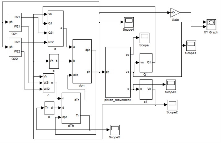
Table 1Computational parameters of the hydraulic damper
Parameter | Symbol | Value | Parameter | Symbol | Value |
Flow coefficient of relief valve | 0.82 | Flow coefficient of throttle hole | 0.8 | ||
Diameter of throttle hole / m | 5×10⁻³ | Density of oil / kg∙m-3 | 872 | ||
Initial pressure of buffer chamber / Pa | 1.3×10⁷ | Set pressure of relief valve / Pa | 2.5×10⁷ | ||
Flow area for relief valve / m2 | 7.2×10⁻³ | Inner diameter of buffer chamber / m | 0.36 | ||
Isothermal bulk modulus / Pa | 7×10⁸ | Cubical expansion coefficient / K-1 | 6.5×10⁻⁴ | ||
Special heat of oil / J∙Kg-1∙K-1 | 7949.6 | Initial temperature / ºC | 33 | ||
Initial compress of spring / m | 0.1 | Spring stiffness / N∙m-1 | 2×10⁴ | ||
Mass of pile hammer / kg | 7000 | Diameter of rod / m | 0.15 | ||
Impact velocity / ms-1 | 5.73 | Return oil pressure / Pa | 1×10⁶ |
Fig. 6Simulation results of the performance for hydraulic damper
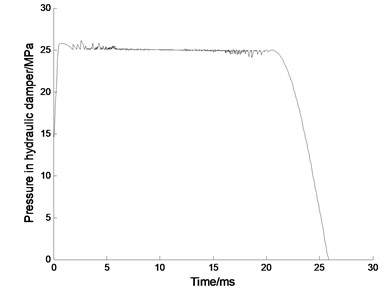
a) Pressure in hydraulic damper
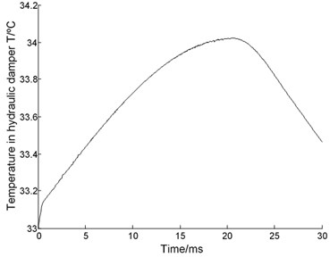
b) Temperature in hydraulic damper
The hydraulic damper takes about 20.6 ms to complete the process of energy absorption, which is 0.6 ms longer than the test results with the relative error of 3 %. In the process, the highest temperature in the hydraulic damper reached to 34.04°C, which is 1.04°C higher than the initial temperature. There is a difference in the initial time of energy absorption that is caused by the moving time for the cylinder to strike the damper. The numerical simulation can simulate the actual performance of the hydraulic damper in approximate by contrasting the experimental results and the numerical simulation, which verified the correctness of the thermal-hydraulic model.
5. Evaluation of some key factors by using the thermal-hydraulic model
5.1. Throttle hole diameter
Changing the value of throttle hole diameter , the curves of velocity, displacement, acceleration of floating piston and pressure for buffer chamber are acquired as Fig. 7(a)-(d) shown, respectively. With the throttle hole diameter increasing, the required time of floating piston velocity reduced to 0 is basically the same, approximately 20.6-20.7 ms, and the working stroke is basically the same too, about 124.2 mm; the mutation time of floating piston acceleration moves up, and the floating piston velocity increased at this time. Therefore change of the throttle hole diameter has little effects on working time and stroke; the time for buffer chamber pressure increased to the setting pressure of relief valve increase with the increase of the throttle hole diameter, and also the damping effect of throttle hole. In other words, the working scope with soft characteristic increased with the throttle hole diameter increasing.
Fig. 7Effect of throttle hole diameter dh1
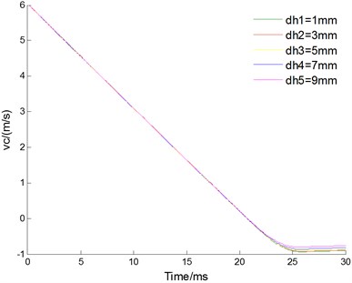
a) Velocity of floating piston
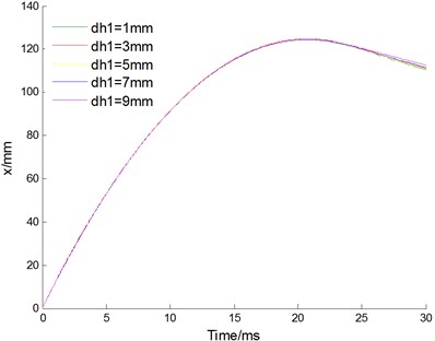
b) Displacement of floating piston
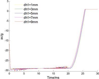
c) Acceleration of floating piston
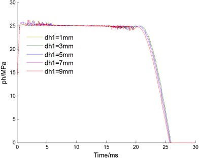
d) Pressure for buffer chamber
5.2. Inner diameter of buffer chamber
Changing the value for the inner diameter of the buffer chamber , the curves of velocity, displacement, acceleration of floating piston and pressure for buffer chamber are acquired as Fig. 8(a-d) shown, respectively. With the inner diameter increasing, the working time of cushion reduces from 21.7 ms to 10.3 ms; the working stoke of cushion reduces from 130.69 mm to 55.81 mm; the maximum impact acceleration of the cushion increases from 28.6 to 86.4 times of gravity acceleration; the buffer chamber pressure of the cushion increases from 25.7 MPa to 48.7 MPa. Inner diameter has great effects to characteristic of the hydraulic damper. With the inner diameter increasing, the working time and stroke of cushion are reduced. However, the increased inner diameter makes buffer chamber pressure increased too, which may cause breakage of the seal for buffer chamber. Therefore, inner diameter should be chosen the maximum value under the permission pressure of buffer chamber.
Fig. 8Effect of inner diameter Dh
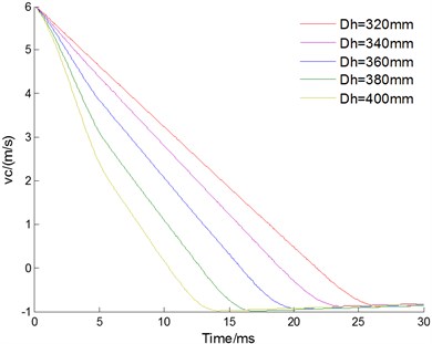
a) Velocity of floating piston
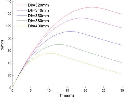
b) Displacement of floating piston
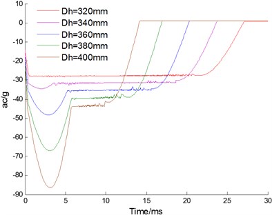
c) Acceleration of floating piston
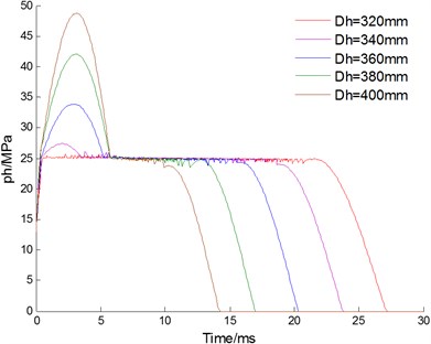
d) Pressure for buffer chamber
5.3. Setting pressure of the relief valve
Changing the setting pressure of the relief valve, the curves of velocity, displacement, acceleration of floating piston and pressure for buffer chamber are acquired as Fig. 9(a-d) shown, respectively. With the set pressure increasing, the working time of cushion reduces from 26.8 ms to 20.6 ms; the working stroke of cushion reduces from 140.2 mm to 124.2 mm; the maximum pressure fluctuation reduces from 17 MPa to 1.2 MPa. The maximum impact acceleration of the cushion reduces from 38.8 to 28.5 times of gravity acceleration when the set pressure increases from 16 MPa to 22 MPa, and increases to 30.4 times of gravity acceleration when the set pressure increases from 22 MPa to 25 MPa. Therefore, the setting pressure of the relief valve also has a great effect to characteristic of hydraulic damper. With the setting pressure increasing, the working time and stroke, and the pressure fluctuation reduces. The maximum impact acceleration reaches the minimum when the set pressure is 22 MPa.
Fig. 9Effect of setting pressure phset

a) Velocity of floating piston
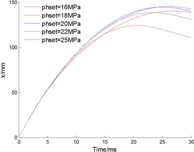
b) Displacement of floating piston
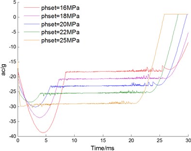
c) Acceleration of floating piston
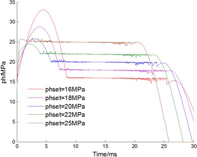
d) Pressure for buffer chamber
6. Conclusions
Basing on analyzing structure and working principle of a hydraulic damper with large flow, considering the effects of temper, a thermal-hydraulic model for the hydraulic damper has been proposed using thermodynamics and fluid dynamics theory. The effects of some parameters to characteristics of the hydraulic damper with large flow have been simulated, and the results are shown as follows:
(1) Change of the throttle hole diameter has little effects on working time and stroke. The time for buffer chamber pressure increased to the setting pressure of the relief valve can be extended by increasing the throttle hole diameter, and also the working scope with soft characteristic.
(2) The inner diameter has great effects to characteristic of the hydraulic damper. With the inner diameter increasing, the working time and stroke of cushion are reduced. However, the increased inner diameter makes buffer chamber pressure increased, which may cause breakage of the seal for buffer chamber.
(3) The setting pressure of the relief valve also has great effect to characteristic of hydraulic damper. With the set pressure increasing, the working time and stroke, as well as the pressure fluctuation reduce.
References
-
Kim D. H., Park J. W., Lee G. S., et al. Active impact control system design with a hydraulic damper. Journal of Sound Vibration, Vol. 250, Issue 3, 2002, p. 485-501.
-
Ping Y. Experimental and mathematical evaluation of dynamic behaviour of an oil-air coupling shock absorber. Mechanical Systems and Signal Processing, Vol. 17, Issue 6, 2003, p. 1367-1379.
-
Wang Y., Hua H. X. Shock Theory and Application of Modern Vehicle. Science Press, Beijing, 2005.
-
Tan R. H., Chen Y., Lu Y. X. Simple nonlinear model for shock absorbers. Chinese Journal of Mechanical Engineering, Vol. 12, Issue 3, 2002, p. 193-198.
-
Wang W. L., Xu G. X. Fluid formulae for damping changeability conceptual design of railway semi-active hydraulic dampers. International Journal of Non-Linear Mechanics, Vol. 44, Issue 7, 2009, p. 809-819.
-
Duym S., Stiens R., Reybrouck K. Evaluation of shock absorber models. Vehicle System Dynamics, Vol. 27, Issue 2, 1997, p. 109-127.
-
Duym S. Simulation tools, modelling and identification for an automotive shock absorber in the context of vehicle dynamics. Vehicle System Dynamics, Vol. 33, Issue 4, 2000, p. 261-285.
-
Samantaray A. K. Modelling and analysis of preloaded liquid spring damper shock absorbers. Simulation Modelling Practice and Theory, Vol. 17, Issue 1, 2009, p. 309-325.
-
Jiao S. J., Wang Y., Zhang L., et al. Shock wave characteristics of a hydraulic damper for shock machine. Mechanical Systems and Signal Processing, Vol. 24, Issue 5, 2010, p. 1570-1578.
-
Van W., Sonntag R. E. Fundamentals of Classical Thermodynamics. Wiley, New York, 1985.
-
Yang G. P. Research on design theory on the return oil chamber of a new hydraulic impactor. China Journal of Highway and Transport, Vol. 15, Issue 1, 2002, p. 113-116.
-
Zhang X. Study of fuzzy control on mechatronical hydraulic hammer. China Journal of Highway and Transport, Vol. 16, Issue 4, 2003, p. 111-115.
-
Guo Y., Hu J. P., Zhang L. Y. Finite-element analysis of multi-body contacts for pile driving using a hydraulic pile hammer. Proceedings of the Institution of Mechanical Engineers, Part C: Journal of Mechanical Engineering Science, Vol. 255, Issue 5, 2011, p. 1153-1161.
-
Li C. G., Jiao Z. X. Calculation method for thermal-hydraulic system simulation. Journal of Heat Transfer, Vol. 130, Issue 8, 2008, p. 84503-84508.
-
Jiao Z. X., Gao J. X., Hua Q., Wang S. P. The velocity synchronizing control on the electro-hydraulic load simulator. Chinese Journal of Aeronautics, Vol. 17, Issue 1, 2004, p. 39-46.
-
Jiang P. X., Fan M. H., Si M. H., et al. Thermal-hydraulic performance of small scale mico-channel and porous media heat exchanges. International Journal of Heat and Mass Transfer, Vol. 44, Issue 5, 2001, p. 1039-1051.
About this article

The authors thank the reviewers for their valuable comments and the Science and Technology Department of Hunan Province for the financial support of this work under Grant No. 2008JT1014.
