Abstract
In order to satisfy the adjusting of recoil system of the gun to different firing conditions, a magneto-rheological fluid (MRF) damper with double annular channel is proposed, which can satisfy the maximum recoil displacement and reduce the force acting on the gun carriage. The double annular channels MRF damper has less zero field damping force and has a larger range of resistance regulation. The dynamic model of MRF damper considering inertia effect is established, and the mechanical properties of MRF damper are tested. The experimental results shown that the calculated values are in good agreement with the experimental values. According to the gun recoil dynamic model of MRF damper, a sliding mode tracking controller based on constant velocity reaching law is designed, and the recoil process of the gun is simulated. The results shown that the MRF damper damping force under the sliding mode control algorithm has a plateau effect, which can be used in the recoil motion control of the gun.
1. Introduction
As one of the key components of artillery, the main function of the recoil brake is to reduce the acting force on the carriage while firing, and plays an important role in improving the firing accuracy and mobility of the artillery. The traditional recoil brake is a passive damping control device. The structural parameters are designed according to the usual angle and propellant charges. So, the damping characteristics cannot be changed during a firing process.
Magneto-rheological fluid (MRF) damper, as an intelligent damping control device, have become one of the most important research directions in the fields of shock absorption due to its advantages of real-time controllability of damping force, large force output range, short response time and low energy consumption. MRF dampers have been widely used in the research of seat suspension, structural damping, bridge cables and aircraft landing gear [1-4]. The research focus of domestic and foreign experts on this fields mainly concentrated in low speed, low frequency research. With the development of Magneto-rheological (MR) technology, some authors began to apply MRF dampers to recoil application of weapon system. Hao et al. [5] applied the MRF damper developed by Lord Company to the recoil device of the large caliber machine gun of Apache helicopter, combined with the digital control system, can effectively reduce the recoil resistance of the machine gun during firing. Ahmadian et al. [6] applied MRF damper in the recoil test of single shot of large caliber rifle, and found that MRF damper can effectively adjust recoil stroke. Zhang Lijie et al. [7, 8] tested the dynamic characteristics of MRF damper under shock load, and identified the parameters of the model. These studies have found that MRF dampers can effectively regulate recoil motion of weapons.
Based on the analysis of the working principle of the traditional recoil brake and the recoil motion characteristics of gun, a MRF damper with single cylinder and double annular channels is designed, which has a larger resistance adjustment range compared with the single annular channel MRF damper. The recoil motion of fun is approximate to the shock motion of high speed and heavy load. Inertia effect should be considered when establishing dynamic model. The mechanical characteristics of the MRF damper at constant speed and variable speed are tested, and the correctness of the dynamic model is verified. Considering the short recoil time and complex signal of MRF damper, a sliding mode control algorithm with strong robustness is designed.
2. Working principle of the MRF damper
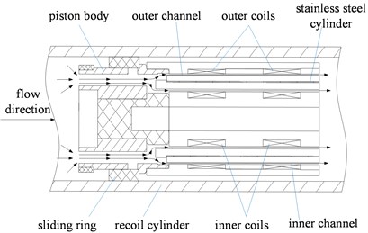
The MRF damper is designed with parallel double MRF channels and double piston rods, including piston assembly, excitation coil assembly, piston rods, recoil cylinder and sealing elements. The excitation coil assembly has an inner and outer annular damping channels, and the flow channels between the excitation coil assembly and the piston assembly connect the left and right chambers. The diameter of the piston rods at both ends are the same, so that the inner volume of the MRF damper is not changed when the piston rods move relative to recoil cylinder. It is stipulated that the piston rods moves to the left side relative to recoil cylinder as the recoil direction, and the rightward movement is in the count-recoil direction.
As shown in Fig. 1, two series coils are used to excite the inner and outer annular channels to increase the length of the damping channels. The winding direction of the two series coils is opposite, so that the magnetic field of the middle part of the two coils is superimposed. Magnetic routes produced by inner and outer coils are separated by stainless steel cylinder to prevent mutual interference of magnetic fields produced by inner and outer coils. There are radial and axial flow holes on the piston body, and the radial flow holes are connected with the inner and outer annular channels. The sliding ring is sleeved on the piston body. the left and right sliding of the sliding ring can control the switch of the radial flow holes, and the piston body and the sliding ring constitute the valve mechanism. The magnetic field intensity in the annular damping channels regions corresponding to the inner and outer coils (outer and inner) are almost zero. These regions are called the inactivation region, while the other regions are called the activation regions. The direction of the magnetic field in the activation regions is perpendicular to the direction of the flow of MRF.
Fig. 1Partial section view of the MRF damper
2.1. Dynamic modeling of the MRF damper
The recoil motion of gun can be simplified to high-speed shock motion, so the Herschel-Bulkley constitutive model is adopted. The Herschel-Bulkley model can describe the shear thinning phenomenon of magnetorheological fluids at high-speed in the activation regions. During the recoil motion of MRF damper, the damping force consists of the hydraulic damping force inside the damper and the friction force between the piston rod and the sealing elements. The hydraulic damping force inside the damper is approximately the product of the pressure difference between the two ends of the piston valve and the net sectional area inside the damper. The pressure difference is the sum of the pressure drop produced by the MRF flowing through the activation regions, the inactivation regions and the piston body.
Considering the inertia effect of MRF in annular damping channels during shock motion, the inner channel is taken as an example to analyze. Pressure drop produced by internal channel activation regions can be express as:
where is inner sectional area of cylinder, is sectional area of piston rod, is velocity ratio of the inner channel to the outer channel, is fluid behavior index, and is inner and outer radius of the inner channel, , is gap width of the inner damping channel, is thickness of the plug flow regions, is dimensionless plug flow thickness, is viscosity coefficient, is length of activation regions of inner damping passage, is velocity of piston rod, is density of MRF, is mean velocity of internal damping channel.
Nonlinear equation of as Eq. (2):
where is shear yield stress of the inner channel MRF. The value range of dimensionless plug flow thickness a is (0, 1), and the value of can be obtained by iterative root searching.
Pressure drop produced by the inactivation region in inner channel can be express as:
where is total length of inner channel.
Total pressure drop in inner channel is:
Similarly, the pressure drop of outer channel can be obtained for . The pressure drop at both ends of the channel can be simplified as the mean value of the pressure drop inner and outer channels:
The pressure drop produced by MRF through the piston body can be obtained by the Bernoulli equation, As shown in Eq. (6):
where is the channel area of piston body.
So, the total pressure drop inside the MRF damper is:
It is very difficult to accurately calculate the friction force of MRF damper during recoil. In order to simplify the calculation, friction is used as a constant of 400 N. The total damping force of MRF damper during recoil motion is:
2.2. Comparison between theoretical and experimental values of the MRF damper
In order to evaluate the mechanical properties of MRF damper and verify the correctness of the dynamic model, the mechanical properties of MRF damper were tested. Test bench test system includes material testing machine, industrial computer, MRF damper, DC regulated power supply, current controller, notebook computer. The displacement waveforms of the material testing machine are triangle wave (frequency 0.333 Hz, amplitude 35 mm) and sine wave (frequency 0.5 Hz, amplitude 20 mm), and the coil is connected with constant current. The mechanical properties of MRF damper under constant speed and variable speed were measured by changing the coil current value.
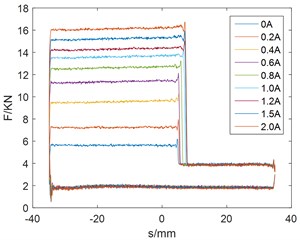
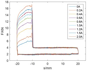
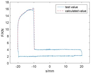
As shown in Fig. 2 and Fig. 3. When the damper is pressed down, the damping force suddenly increases and has a larger adjustment range after the valve closes. The valve is opened and the damping force is small during the pull-up process, which is beneficial to the rapid count-recoil of gun. The damping force increases with the increase of current, which has a larger resistance adjustment range. As shown in Fig. 2, the damper has stable output and reliable performance.
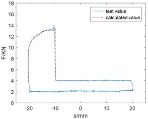
Using MATLAB to compile the dynamic model program, the excitation coils current of 0.8 A, 1.5 A test parameters under sinusoidal motion are brought into the program calculation, and the calculated values are compared with the experimental values as shown in Fig. 3. Generally speaking, the calculated values are in good agreement with the test values.
Fig. 2Damping force and displacement curve: a) trigonometric wave, b) sine wave
a)
b)
Fig. 3Comparison between the calculated value and the test value
a)
b)
2.3. The MRF damper recoil process modeling
Count-recoil resistance of artillery in recoil process is:
Dynamic equation of MRF damper with recoil of artillery can be express as:
where is displacement of piston rods, is velocity of piston rods, and is bore resultant force.
3. Simulation of sliding mode control
Sliding mode control is used to motion control of the system. The motion of sliding mode control system has two stages: approaching motion and sliding mode motion. In the approaching motion stage, the trajectory of the system in the state space is located outside the switching surface or crossing the switching surface finite times; in the sliding mode motion stage, the system “slides” near the switching surface and along the switching surface. According to the principle of sliding mode, the condition that sliding mode can be reached is only to ensure that the controlled object reaches the switching surface in a limited time from the point of motion in any initial state. The reaching law can be used to improve the dynamic quality of the approaching motion.
3.1. Controller design
Combined with the above dynamic modeling of MRF damper, the controller of sliding mode control method is designed. Set:
The recoil motion equation a of MRF damper can be rewritten as:
The control target is expressed as:
When the tracking error is defined as and the ideal pressure response of the MRF damper is defined as 16 MPa, the error and its reciprocal are expressed as:
In this paper, the sliding mode method based on constant speed reaching law is chosen, and the factor is introduced on the basis of constant speed reaching law. Get the reaching law is:
Selecting switch function , there are:
Simultaneous Eq. (15)-(17), get the control law is:
For , there is 0, meet Lyapunov stability.
3.2. Result analysis
In order to verify the validity of the controller, a Simulink simulation model is built for numerical simulation. Initial state of system: 0, 0. Select control parameters for: 0.1, 1800, 0.8.
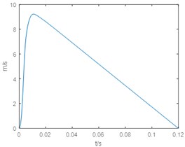
As can be seen from Fig. 4, 5, the system can achieve the control target in about 0.02 s and has a fast response speed. The internal pressure of the MRF damper is close to 16 MPa, and the control precision is high. Damping force has a plateau effect. The speed of piston rod is steady, the pressure response of the damper chamber is not trembled, and the control algorithm is robust.
Fig. 4Internal pressure response of MRF damper
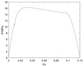
Fig. 5Velocity time curve
4. Conclusions
The dynamic model can describe the mechanical characteristics of MRF damper in variable speed motion. The sliding mode control algorithm can be used for the recoil control of MRF damper in the recoil process of gun.
References
-
Hiemenz G. J., Hu W., Wereley N. M. Semi-active magnetorheological helicopter crew seat suspension for vibration isolation. Journal of Aircraft, Vol. 45, Issue 3, 2008, p. 945-953.
-
Mei Z., Peng Y., Li J., et al. Experimental and analytical studies on stochastic seismic response control of structures with MRF dampers. Earthquake and Structures, Vol. 5, Issue 4, 2013, p. 395-416.
-
Sun Hongxin, Wang Xiuyong, Chen Zhengqing, et al. Wind-induced torsional vibration control effect of bridge with magnetorheological tuned liquid column damper. China Journal of Highway and Transport, Vol. 23, Issue 1, 2010, p. 58-65.
-
Mikułowski G. M. Adaptive Impact Absorbers Based on Magnetorheological Fluids. Smart Technology Centre, Institute of Fundamental Technological Research, Polish Academy of Sciences, Warsaw, Poland, 2008.
-
Hao K. Rotor Blade Lag Damping Using Embedded Chordwise Absorbers. The Pennsylvania State University, Pennsylvania, US, 2001.
-
Ahmadian M., Poynor J. C. An Evaluation of magneto rheological dampers for controlling gun recoil dynamics. Shock and Vibration, Vol. 8, Issues 3-4, 2001, p. 147-155.
-
Zhang Lijie, Wang Jiong, Qian Linfang Experimental analysis of the dynamic performance of magneto-rheological dampers under impact loads. Acta Armamentarii, Vol. 29, Issue 5, 2008, p. 532-536.
-
Zhang Lijie, Wang Jiong, Qian Linfang Dynamic performance analysis and model parameter identifications of MRF dampers under impact load. Chinese Journal of Mechanical Engineering, Vol. 45, Issue 1, 2009, p. 211-217.
About this article

