Abstract
Design of permanent magnet synchronous machines becomes more of an issue for all systems lately. There are many parameters that have influence for machine design. Each parameter should have optimized and their effects on the system should be determined. Any desired pre-design have been done for machine design except a few paper and it only showed by of Finite element analysis (FEA). In this article, analytical method is used in permanent magnet synchronous machine design and the effects of geometric on the performance of machine are presented. Magnetic equivalent circuit (MEC) model is used as numeric method. It is observed that the proposed MEC model is pertinent to Speed PC-BDC model and FEA. Besides proposed MEC model provides to calculate performances of the machines which have the desirable slot/pole combinations correctly. Proposed model is applied on the recently increased fractional slot direct drive synchronous generators.
1. Introduction
Permanent magnet synchronous machine is used in a large-scale area including automotive, industrial and energy sector. Permanent magnet synchronous machine drawback is torque ripple. This cause vibration and noise. Permanent magnet synchronous machines divide into two parts according as the situation of slot/pole combination is integer or fractional. In case of the slot/pole combination is fractional, the machine is called fractional slot permanent magnet synchronous machine. Over the last few years, as FSCW started gaining many attention, one of the key challenges was to understand the theory of operation of FSCW [1].
It is important to define properly the magnetic fields curves in the air gap permanent magnet synchronous machine to evaluate the performance of machine like analytically obtained moment and back-EMF. There are many parameters which affect the performance of machine.
Magnetic circuit models have been used to study a wide variety of machine types and configurations including switched reluctance, induction, surface PM variable reluctance, brushless dc (BLDC), and flux switching PM machines. The majority of the reported MECs are used for prediction of basic machine performance characteristics such as torque production and terminal voltage-current characteristics [2].
MEC or reluctance network analysis (RNA) and its application for electrical machines were introduced by Ostovic’. Improvements were made in MEC/RNA to estimate the performance of electromagnetic devices and electrical machines. Performance analysis using MEC is receiving more attention, especially during the early design optimization. Its key advantages are the higher accuracy than the analytical and lumped parameter models and lower computational time than FEA [3].
The design of those machines is related to the proper calculation of characteristics of preliminary designs. Both, magnets loadlines and the reluctances of the magnetic circuit, are the most important parameters to be calculated. With regard to magnet’s characteristics, these vary according to the operating point of the machine, and this must be taken into consideration to choose them.
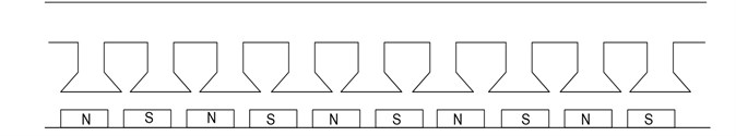
In this paper, a complete study about the reluctances of the machine is done in order to calculate the total flux flowing through the machine. The current machine is permanent magnet synchronous machine which have 10 poles and 9 slots.
2. Magnetic equivalent circuit design
The most important parameter of torque at permanent magnet synchronous machines is magnetic energy. There are several methods to calculate the magnetic energy. Most commonly used methods are finite elements method and MEC method.
In general, FEA can be used to calculate the characteristics of electrical machines. However, much time has to be devoted in order to prepare the FE mesh models before performing FEA. FEA also requires much computational time to perform the calculation. FEA is not very adequate for theoretical investigation of the analyzed results due to the complexity. Therefore, simple magnetic circuit analysis that can calculate the characteristics in a short amount of time is needed for efficient structural design of the machines. It will also give better theoretical insight into the analyzed results than FEA [4].
The basic idea of MEC method is the use of the analogy between magnetic and electric fields. With this method, the simulation problem reduces to analysis of a network consisting of admittances, current and/or voltage sources. In order to construct this network, the electromagnetic system and its surrounding space is partitioned into geometrically simple elements. Under the ideal assumption that the flux of the field in an element is constant and can only flow in two directions. The admittance depends on the geometry of the element and the material parameter. The permanent magnet and the coil are modelled with a current and/or a voltage source. Through logical connection of these elements, an equivalent magnetic network emerged. The topology of the network is determined by the direction of the flux lines in the system and the geometrical material succession of the field elements. Nonlinear admittances are well represented by their characteristic flux density versus field strength curves. The resulting nonlinear network analysis leads to a fast and for technical purposes sufficiently accurate simulation method [5].
The magnetic circuit approach has the advantages of simplicity and computational efficiency, so it is well suited for rapid performance evaluation at the initial design stage.
Magnetic circuits are more convenient to calculate the machine characteristics and can give better theoretical insight into the calculated results [6]. MEC method is calculated for both load and no-load conditions of machine thus armature effect is taken into account.
3. 10 pole 9 slot permanent magnet synchronous generator MEC analysis
Two dimensional cross-section of machine shows in Figure 1. The stator has windings concentrated around each stator pole. The number of winding turns of each phase is 216. The rare-earth magnet “Nd-Fe-B” is buried in the rotor iron. Residual magnetic flux density and coercive force of the permanent magnet are about 1.3 T and 1000 kA/m, respectively.
Fig. 1a) 2D cross-section of the permanent magnet synchronous machine, b) 3D cross-section of the permanent magnet synchronous machine
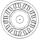
a)
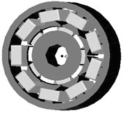
b)
For the simplified shape of the MEC method, first it is studied on the slotless structure.
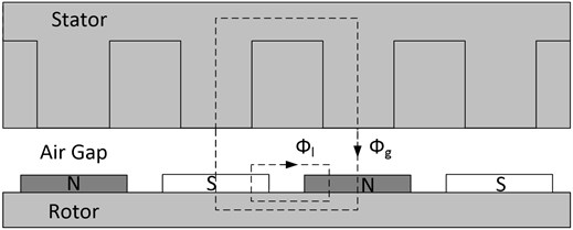
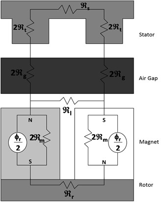
At Figure 2, a cross-section of the permanent magnet synchronous machine is shown. Flux of each magnet is from pole to pole. In this situation, irrelevant to how much threads the magnet includes, direction of flow is from to .
Fig. 2Cross-section of the permanent magnet synchronous machine
Basic MEC for slotless structure is shown at Figure 3.
Before Back-EMF calculation, air-gap flux density () is found by the solution of MEC at Figure 2. The solution of this circuit is used for the solution of the circuit at Figure 4d.
Fig. 3MEC for slotless structure [7]
![MEC for slotless structure [7]](https://static-01.extrica.com/articles/14515/14515-img4.jpg)
Fig. 4Simplified MEC [7]
![Simplified MEC [7]](https://static-01.extrica.com/articles/14515/14515-img5.jpg)
According to Fig. 4(d):
as it is stated at above:
the statement is obtained.
is the reluctance of the magnet, is the reluctance of air gap, is the reluctance of rotor, is the reluctance of stator, leakage reluctance and is the leakage factor and its value is less than one.
4. A. Magnetic equivalent circuit at no-load condition
At Figure 5, the cross-section of the permanent magnet synchronous machine with slotted structure is shown. Basic MEC for slotted structure are shown at Figure 6.
Fig. 5The cross-section of the slotted structural permanent magnet synchronous generator
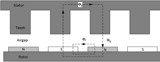
Fig. 6MEC for slotted structure
Before back-EMF calculation, air-gap flux density () is found by the solution of MEC at Figure 6. The solution of this circuit is used for the solution of the circuit at Figure 6:
B. Magnetic equivalent circuit at load condition
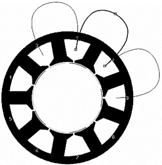
Fig. 7The winding structure of a 9 slot 10 pole machine
The following equation is used in order to obtain the number of MEC column at load condition :
Fig. 8MEC at load condition
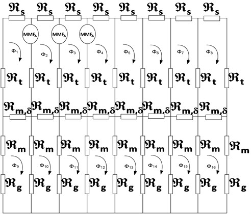
While the total flux is:
The effect of armature reaction on magnetic circuit can be calculated. At the same time, load condition equivalent circuit can be used to calculate inductance.
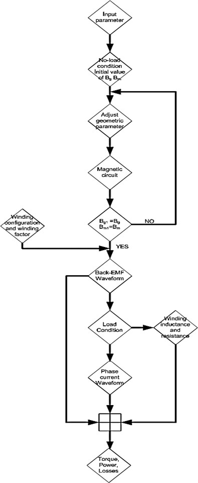
4.1. Permanent magnet synchronous generator flow chart
Fig. 9Flow chart
5. Permanent magnet synchronous generator back-EMF analysis
The analytical model of permanent magnet synchronous generator in Fig. 10 is a 9-slot 10-pole permanent magnet synchronous generator.
The analytical method assumes that the forward direction of flux derives from magnet pole to armature, that the generated voltage and induced current are chosen to produce flux in the same direction, that armature moves rightward relatively to magnet poles, that reference axis is the centre line of the slot between phase A and phase B windings, and that timing starts at the moment of reference axis passing by the position of zero electrical degrees [8].
Fig. 109 slot 10 pole configuration
Optimum magnetic flux density is shown at Figure 11.
Fig. 11Optimum magnetic flux density
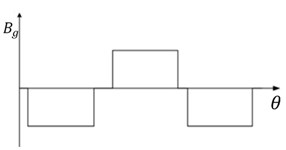
The function of magnetic flux density according to the rotor angle [6]:
The air flux density of the machine with 9 slots and 10 poles is shown at Figure 12. FEA analysis is shown at Figure 13. Mesh structure is shown at Figure 14.
As it is a show at Figure 12, the density of air gap flux changes according to the turning of rotor. Magnetic flux function:
is obtained from flux density.
Due to the Faraday’s law, the change of flow in respect of time gives back-EMF. According to this:
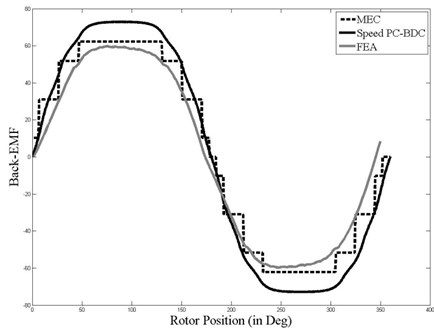
Back EMF wave form of a 9 slot 10 pole machine is shown at Fig. 15.
Fig. 12Air gap magnetic flux density
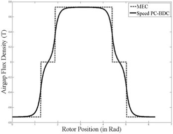
Fig. 13Magnetic flux density from FE
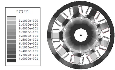
Fig. 14Mesh structure
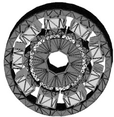
Fig. 15Back-EMF waveform
6. Permanent magnet synchronous generator torque analysis
Cogging torque and electromagnetic torque of a PM machine are calculated according to Maxwell’s stress tensor method as:
According to Arkkio’s method, it is better to compute the average value of the electromagnetic torque over the entire air-gap surface. So the torque can be calculated as:
where is air gap surface constituted by the layers between stator and rotor, is air gap length.
According to virtual work method, electromagnetic torque is equal to the derivative of the magnetic co-energy with respect to rotor angle at constant current [9]:
According to equation (17):
is obtained.
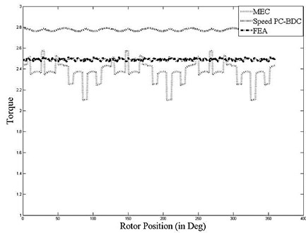
At Figure 16, the torque wave form which is obtained from equation (18) is shown.
Fig. 16Torque wave form
7. Conclusion
In this article, the electromagnetic design algorithm of slot/pole permanent magnet synchronous machine with 10 poles and 9 slots is proposed. Proposed design algorithm compared to Speed PC-BDC program and FEA. In the study, 3.16 GHz Intel Core 2 Quad 3.49 GM RAM computer was used and it was observed that total number of elements is 234745 and the total CPU time is 60 minutes for FEA, 1 second for MEC. There is a 10 % difference is seen between the torque and Back-EMF results. Proposed MEC model is suitable for the design and analysis of permanent magnet synchronous machines with any different number of slot/pole. Proposed PM model is a function of slot and pole number. In this way, the model makes it possible to perform an analysis quicker than FEA.
References
-
El-Refaie A. Fractional-slot concentrated-windings synchronous permanent magnet machines: opportunities and challenges. IEEE Transactions on Industrial Electronics, Vol. 57, No. 1, 2010.
-
Bianchi N., Bolognani S., Grezzani G. Design considerations for fractional-slot winding configurations of synchronous machines. IEEE Trans. Ind. Appl., Vol. 42, No. 4, 2006, p. 997-1006.
-
Tariq A. R. Iron and magnet losses and torque calculation of interior permanent magnet synchronous machines using magnetic equivalent circuit. IEEE Trans. on Magnetics, Vol. 46, No. 12, 2010, p. 4073-4080.
-
Hosoi T., Shima K., Fukami T. Magnetic circuit analysis of permanent-magnet-assisted salient-pole synchronous machines under steady states. IEEE International Electric Machines and Drives Confence, 2011, p. 457-462.
-
Widyan S. Design, Optimization, Construction and Test of Rare-Earth Permanent-Magnet Electrical Machines with New Topology for Wind Energy Applications. Ph. D. Dissertation, Technische Universität Berlin, Berlin, Germany, 2006.
-
Strous T. D. Design of a permanent magnet radial flux concentrated coil generator for a range extender application. M. Sc. Thesis Report, Delft University of Technology, Delft, Netherlands, 2010.
-
Hanselman D. C. Brushless Permanent Magnet Motor Design. McGraw Hill, Maine, 1994.
-
Wu J., Wang Y., Li X., Zhang J., Wu T. Effect of parameters on back-EMF in permanent magnet brushless DC motor with concentrated winding. IEEE Automation Congress, 28 Sept.-2 Oct. 2008, p. 1-4.
-
Vu Xuan H., Lahaye D., Ani S. O., Polinder H., Ferreira J. A. Effect of design parameters on electromagnetic torque of PM machines with concentrated windings using nonlinear dynamic FEA. International Electric Machines & Drives Conference, Niagara Falls, ON, 2011, p. 383-388.
About this article

