Abstract
This paper presents an efficient approach to simulate Lamb wave propagations in thin plate structures by using new time domain spectral plate elements. A novel approach is proposed to incorporate the coupling of piezoelectric transducers within the two-dimensional plate element. The diagonal mass matrix is obtained by using a simple method with less computational effort. Detailed formulations are given. The benchmark problem of a thin aluminum plate with two surface-mounted piezoelectric transducers was investigated in detail. Comparisons are made with results obtained by using ABAQUS to verify the developed spectral plate element. It is shown that the proposed element can efficiently simulate the propagation of Lamb wave generated by a piezoelectric actuator and picked up by a piezoelectric sensor.
1. Introduction
It is well known that detecting small damage in structures is an important and challenging task [1-2]. Recently, the use of Lamb wave based technology in structural health monitoring has made significant progress [3-5]. It is observed that the behavior of Lamb wave is very complicated. For example, the wave occurs in multiple modes which can convert into each other under special conditions during propagation [6]. These phenomena make the Lamb wave based monitoring technology more complicated in order to detect and locate the failures. Therefore, it is important to understand thoroughly the complex behavior of the Lamb wave interacting with different kinds of damage in structures to reduce the cost and time in the design process of such structural health monitoring systems. Besides the experimental investigations, numerical simulations will definitely play an important role in design of efficient Lamb wave based monitoring systems.
Although different higher order finite element (FE) schemes are available for simulations of Lamb waves [7], however, the time domain spectral element method is a more promising method for simulating wave propagation in complex structures [8-18]. The time domain spectral element method combines the accuracy of the global pseudospectral method with the flexibility of the local finite element method thus can accurately simulate the wave propagation in structures in terms of both phase and amplitude.
For real Lamb wave based structural health monitoring systems, the wave is usually generated by piezoelectric (PZT) actuators and picked up by PZT sensors. Therefore, the piezoelectric coupling effect should be considered in the numerical simulations. Currently most numerical simulations of Lamb wave propagations [8-18] have not considered the coupling effect to reduce the modeling effort. Only fewer papers [19, 20] have considered the piezoelectric coupling effect. In doing so there-dimensional (3-D) spectral elements [19] have been used to take into account the piezoelectric coupling effect, however, the computing time and memory may become impractical for real complex structures. To reduce the computational resource and simplify the problem, a new approach is proposed to incorporate the coupling effect within the spectral element framework [20]. Although the method reported in [20] seems feasible, it may still suffer some shortages. For example, the piezoelectric effect in the thickness direction is not considered, a non-diagonal mass matrix may be resulted since PZT elements are usually mounted only on one face of the host plate in practice. Therefore, it is still necessary to investigate other efficient ways.
For plate structures, it is desirable to use a two dimensional (2D) plate element to reduce the modeling effort as well as the computational resources. In this paper, a new time domain 2D spectral element is proposed to incorporate the coupling of piezoelectric transducers. Detailed formulations are presented. To validate the formulations, a benchmark problem presented in [19] is analyzed. Numerical results are compared with data obtained by ABAQUS with fine meshes. Conclusions are drawn based on the results reported herein.
2. Formulations of the new spectral plate element
2.1. Displacement and strain fields
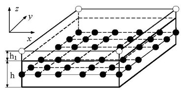
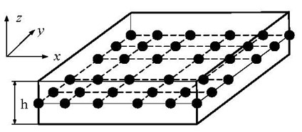
To model the 3-D behavior of the Lamb wave propagation in plates by using a 2-D spectral plate element, seven variables, , , , , , , , are introduced. , , are displacement components in the x, y, and z direction and superscripts , , denote the bottom, middle and top surfaces, respectively. The reason to choose these variables will be demonstrated in Section 3. The proposed method is also applicable if more variables are required. Fig. 1 shows a typical 6×6-node line (or simply node) 2-D spectral plate element with (Fig. 1a) and without (Fig. 1b) a PZT layer. It is seen that the modeling effort will be reduced since only 2-D elements are involved.
In the global -- coordinate system set in the middle plane of the host plate shown in Fig. 1, the 3-D displacement field of the plate can be written as:
where is the thickness of host plate. Each node, denoted by the filled points in Fig. 1, has seven degrees of freedom , i.e., , , , , , , . Each node in the PZT layer, denoted by the hollow circles shown in Fig. 1a, has only one degree of freedom , the electrical potential. Note that the electrical potential at the interface is assumed to be zero identically.
Fig. 1Sketches of spectral plate element: a) with a PZT layer, b) without a PZT layer
a)
b)
For small strains, the 3-D strain-displacement relations can be written by:
or simply:
where .
For an -node 2-D spectral element, the displacement field in the element can be assumed as:
where are shape functions, denote the nodal degrees of freedom, and and are the one-dimensional Lagrange interpolation functions defined by:
where the distribution of nodes, , , can be the Gauss–Lobatto–Legendre (GLL) points, or the Chebyshev points, or the approximate Lebesgue-optimal grid points, i.e., the expanded-Chebyshev grid points [21-22]. It is shown [18] that the critical time step to ensure stable time integration by using the central finite difference method is the largest if the expanded-Chebyshev grid points are used as the nodes of the spectral element.
Let , where is the thickness of the PZT layer. Since the electric potential on the lower surface of the PZT layer, connected with the host plate, is zero identically, thus the electric voltage in the PZT layer is given by:
where is the shape functions and defined by:
2.2. Constitutive relations
For the host plate, the 3-D stress-strain relation is given by:
where is the elasticity matrix of the material.
For the isotropic piezoelectric element, the adopted constitutive relations are given by:
where and are matrices of the piezoelectric constant and the dielectric constant measured at zero strain, and are vectors of the electric displacement and electric field, respectively.
2.3. Mass and stiffness matrices
Since the general equations can be found in many reference papers [15-20] and textbooks [23], therefore, the detailed formulations of the mass matrix and stiffness matrix for element with and without a PZT layer are omitted.
Due to , the diagonal mass matrix of the element can be obtained by row summation and integrated by using Gaussian quadrature as:
where , , and , are weights and abscissas of Gaussian quadrature, is the determinant of the Jacobian matrix, and for plates with and without a PZT layer are respectively given by:
and:
where and are the mass density of the host plate and PZT layer. It was found that the computational effort in obtaining the mass matrix is only about 25 % of that by the existing GLL quadrature rule [17].
The stiffness matrix of the element with a PZT layer can be partitioned by:
in which and are the volume of the host plate and PZT layer, and are strain matrix and electric field matrix, and are the stiffness matrix related to displacement and electric potential, and is the coupled stiffness matrix, respectively. The stiffness matrix can be obtained numerically by using Gaussian quadrature or GLL rule if GLL points are used as the nodes. Detailed derivations are ommitted and may be found in reference [24].
2.4. The time integration scheme
In terms of the spectral plate element with piezoelectric coupling, the well-known governing differential equations for the wave propagation in plate structures can be written by:
where is the structural mass matrix, is the generalized displacement vector and the over double dots denote the second-order derivative with respect to time , , and are vectors of electric potential, external applied force, and electric charge, respectively.
To simplify the solution procedures, the dynamic interface interaction between the PZT layer and the host structure is neglected. Thus, Eq. (14) is uncoupled. Due to the fact of that is a diagonal matrix, a crucial reduction of the complexity and the cost of the numerical time integration can be achieved by using the central finite difference method [25] to solve the first part of Eq. (14). The second part of Eq. (14) is merely used to compute the output voltage.
3. Results and discussion
To verify the proposed formulations, a benchmark problem presented in [19] is analyzed. A thin aluminum plate with two surface-mounted piezoelectric transducers shown in Fig. 2 is considered. The dimension of the plate and the two piezoelectric transducers are 508 mm×∞ mm×1.02 mm and 6.35 mm×∞ mm 0.25 mm. The poling direction is parallel to the z direction. One piezoelectric transducer on the left side is used as the actuator and the other as the sensor. A uniform voltage is input on the piezoelectric element’s upper surface. Since this problem can be regarded as a plane strain problem, thus the displacement in the y direction is set to zero identically. This simplifies the problem for investigation of the effect of spatial resolution in numerical methods without loss of generality [19].
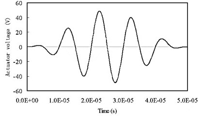
Fig. 3 shows the mesh used in the analysis. Fig. 3(a) is the model by using proposed 6×6 spectral plate element with seven degrees of freedom (DOFs) per node. GLL nodes are used. Fig. 3(b) is the mesh used in the analysis by ABAQUS. In the numerical simulations, the excitation signal is a five-peak tone-burst wave with a center frequency of 100 kHz and kept a peak voltage at 50 V, shown in Fig. 4. The material properties of the host plate are: elasticity modulus 70GPa, mass density 2700 kg/m3, and Poisson’s ratio 0.3. The material properties of the PZT element (Navy Type II), provided by APC company, are listed in Table 1.
Fig. 2Geometry of an aluminum plate
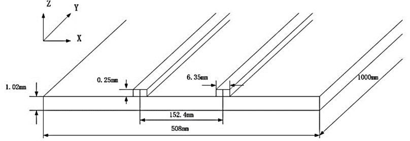
Fig. 3Meshes by (a) proposed spectral plate element and (b) finite plain strain element
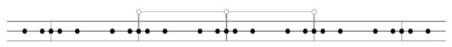
a)

b)
Table 1Material properties of the PZT element
147 GPa | 105 GPa | 93.7 GPa | 113 GPa | 23 GPa | 21.2 GPa |
–3.09 C/m2 | 16.0 C/m2 | 11.64 C/m2 | 1.0-8F/m | 8.04-9F/m | 7700 kg/m3 |
Fig. 4Excitation signal
The sensing signal obtained by the present element is shown in Fig. 5. The data obtained by ABAQUS with plane strain elements are also included in the figure for comparisons. It is seen that the solution obtained by using the proposed spectral element is quantitatively in accord with data obtained by the FEM (ABAQUS). The comparison verifies the formulation of the proposed element and the developed program. Although the solutions match quite well for the mode, however, a small discrepancy is seen in the slower mode. It is pointed out [19] that due to the numerical dispersion error, errors in phase/group velocities exist for both FEM and spectral element method (SPE). For FEM, the solution accuracy would be further improved if smaller size of element than the one shown in Fig. 3(b) is used. For the SEM, an exponential convergence rate is observed and results are more accurate [19]. Due to restriction of the displacement field adopted in the proposed element, however, numerical dispersion error may be larger than the existing 3-D spectral element [19] in the numerical simulation of Lamb wave propagations. Thus, the accuracy of the solution obtained by the proposed element is similar to the result obtained by the FEM. Further increase in the order of the displacement field along direction or refinement of the mesh will definitely reduce the numerical dispersion error, but the computational efficiency will also be decreased.
Fig. 5Comparisons of the output voltage with data by ABAQUS
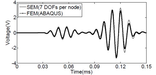
Fig. 6Comparisons of the output voltage with data by ABAQUS
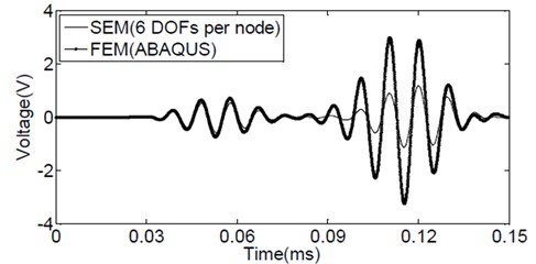
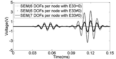
Fig. 7Comparisons of the output voltages obtained by different elements
To investigate the effect of different variation of displacement w along the thickness direction, is assumed a linear function of , the same as the other two displacement components and shown in Eq. (1). Therefore, a six-variable or six-degree of freedom per node spectral plate element can be established. The element is similar to the spectral plate element presented in [18]. Following a similar way, a 6×6-node with six DOFs per node spectral plate element considering the piezoelectric effect can be derived.
The same problem is then re-analyzed by using the 6×6-node with six DOFs per node spectral plate element. Again GLL nodes are used and the same mesh shown in Fig. 3a is adopted in the analysis. The sensing signal obtained by the spectral plate element is shown in Fig. 6. The data obtained by ABAQUS is also included in the figure for comparisons. It is seen that although the agreement is quite well for mode, the magnitude of mode is much smaller than the data obtained by ABAQUS. It suggests that higher order variation of displacement in the thickness direction is necessary. This is the main reason why Eq. (1) is used as the displacement field for the proposed spectral plate element.
Fig. 7 shows the comparisons of output signals obtained by the 6×6-node spectral plate elements with six DOFs or seven DOFs per node. It is seen that if the piezoelectric effect in the poling () direction is not considered, namely, 0, the magnitudes of both mode and mode will be reduced greatly. In other words, keeping the piezoelectric effect in the poling () direction is important to obtain correct amplitude of the sensing signals by PZT sensors.
4. Conclusions
In this paper, a new spectral plate element is proposed to take into account the coupling effect of piezoelectric actuators and sensors. A simple way to formulate the diagonal mass matrix is used to reduce the computational effort. Detailed formulations are given. A benchmark problem is studied. It is shown that without considering the coupling effect of piezoelectric actuators and sensors in the thickness direction may result much smaller amplitude of signals picked up by PZT sensors. The simulated results by the proposed element are well compared to data obtained by ABAQUS with fine meshes. In modeling Lamb wave propagation in plate structures, the proposed element has advantages over the three-dimensinal spectral element in terms of modeling effort, computational time and memory space.
It should be pointed out that the proposed method can also be used for variables higher than seven. In other words, the displacement fields , , along the thickness direction can be assumed even more complicated if additional variables are introduced to increase the accuracy. Besides, variables can be located at any position along the thickness direction, since nodes for a 2-D spectral plate element are actually nodal lines. In this way, the numbering effort will be greatly reduced in establishing a spectral element model for plate structures.
In the present paper, the dynamic interface interaction between the PZT actuator/sensor and the host structure as well as the dynamic behavior of the adhesive interface has not been considered. Further researches are necessary and underway to study these effects.
References
-
Boller C., Staszewski W., Tomlinson G. Health Monitoring of Aerospace Structures. John Wiley & Sons, 2004.
-
Giurgiutiu V. Structural Health Monitoring with Piezoelectric Wafer Active Sensors. Academic Press, Elsevier, 2008.
-
Kessler S. S., Spearing S. M., Soutis C. Damage detection in composite materials using Lamb wave methods. Smart Materials and Structures, Vol. 11, Issue 2, 2002, p. 269-278.
-
Ihn J. B., Chang F. K. Detection and monitoring of hidden fatigue crack growth using a built-in piezoelectric sensor/actuator network, 1: Diagnostics. Smart Materials and Structures, Vol. 13, Issue 3, 2004, p. 609-620.
-
Ihn J. B., Chang F. K. Detection and monitoring of hidden fatigue crack growth using a built-in piezoelectric sensor/actuator network, 2: Validation using riveted joints and repair patches. Smart Materials and Structures, Vol. 13, Issue 3, 2004, p. 621-630.
-
Willberg C., Koch S., Mook G., et al. Continuous mode conversion of Lamb waves in CFRP plates. Smart Materials and Structures, Vol. 21, Issue 7, 2012, p. 1-9.
-
Willberg C., Duczek S., Vivar Perez J. M., et al. Comparison of different higher order finite element schemes for the simulation of Lamb waves. Computer Methods in Applied Mechanics and Engineering, Vol. 241-244, 2012, p. 246-261.
-
Komatitsch D., Barnes C. H., Tromp J. Simulation of anisotropic wave propagation based upon a spectral element method. Geophysics, Vol. 4, 2000, p. 1251-1260.
-
Igawa H., Komatsu K., Yamaguchi I., et al. Wave propagation analysis of frame structures using the spectral element method. Journal of Sound and Vibration, Vol. 277, 2004, p. 1071-1081.
-
Palacz M., Krawczuk M., Ostachowicz W. The spectral finite element model for analysis of flexural-shear coupled wave propagation, Part 1: Laminated multilayer composite. Composite Structures, Vol. 68, 2005, p. 37-44.
-
Sun H., Zhou L. Analysis of damage characteristics for cracked composite structures using spectral element method. Journal of Vibroengineering, Vol. 14, Issue 1, 2012, p. 430-439.
-
Seriani G. 3-D large scale wave propagation modeling by spectral element method on Cray T3E multiprocessor. Computer Methods in Applied Mechanics and Engineering, Vol. 164, Issue 1-2, 1998, p. 235-247.
-
Kudela P., Krawczuk M., Ostachowicz W. Wave propagation modeling in 1D structures using spectral finite elements. Journal of Sound and Vibration, Vol. 300, 2007, p. 88-100.
-
Zak A., Krawczuk M., Ostachowicz W. Propagation of in-plane waves in an isotropic panel with a crack. Finite Elements in Analysis and Design, Vol. 42, 2006, p. 929-941.
-
Peng H. K., Meng G., Li F. C. Modeling of wave propagation in plate structures using three-dimensional spectral element method for damage detection. Journal of Sound and Vibration, Vol. 320, 2009, p. 942-954.
-
Kudela P., Zak A., Krawczuk M., et al. Modeling of wave propagation in composite plates using the time domain spectral element method. Journal of Sound and Vibration, Vol. 302, 2007, p. 728-745.
-
Xu C., Wang X. Efficient modeling and simulations of Lamb wave propagation in thin plates by using a new spectral plate element. Journal of Vibroengineering, Vol. 14, Issue 3, 2012, p. 1187-1199.
-
Wang X., Wang F., Xu C., et al. New spectral plate element for simulating Lamb wave propagations in plate structures. Journal of Nanjing University of Aeronautics & Astronautics, Vol. 44, Issue 5, 2012, p. 645-651.
-
Kim Y., Ha S., Chang F. K. Time-domain spectral element method for built-in piezoelectric-actuator-induced Lamb wave propagation analysis. AIAA Journal, Vol. 46, Issue 3, 2008, p. 591-600.
-
Schulte R. T., Fritzen C. P. Simulation of wave propagation in damped composite structures with piezoelectric coupling. Journal of Theoretical and Applied Mechanics, Vol. 49, Issue 3, 2011, p. 879-903.
-
Boyd J. P. A numerical comparison of seven grids for polynomial interpolation on the interval. Computers and Mathematics with Applications, Vol. 38, 1999, p. 35-50.
-
Brutman L. On the Lebesgue function for polynomial interpolation. SIAM Journal of Numerical Analysis, Vol. 15, 1978, p. 694-704.
-
Ikeda T. Fundamentals of Piezoelectricity, Oxford University Press, New York, 1990.
-
Feng Z. Numerical Simulation of Piezoelectric Actuator Generated Lamb Wave Propagation in Plates. Master Thesis, Nanjing University of Aeronautics & Astronautics, Nanjing, China, March, 2013.
-
Subbaraj K., Dokainish M. A. A survey of direct time-integration methods in computational structural dynamics – I. Explicit methods. Computers & Structures, Vol. 32, Issue 6, 1989, p. 1371-1386.
About this article

The work is partially supported by the National Natural Science Foundation of China (50830201) and by the Priority Academic Program Development of Jiangsu Higher Education Institutions.
