Abstract
The paper presents the results of numerical modeling of air-coupled ultrasonic Lamb waves excitation in an isotropic single layer thin plastic film. The method is applied in the case of non-destructive testing and evaluation (NDT & NDE) of plate structures. Usually air-coupled technique has a very serious drawback: global insertion losses for an entire system may be 120-160 dB typically, so optimum vibration excitation in tested material is needed. A new method of excitation by employing planar phased arrays with rectangular elements has been proposed. A numerical simulation has been performed in order to evaluate air-coupled Lamb wave excitation in an isotropic single layer thin plastic film. The method enables to excite asymmetric Lamb mode in the case, when the velocity of Lamb wave is smaller than ultrasound velocity in the air.
1. Introduction
Many ultrasonic NDT methods use couplants between the material under a test and ultrasonic transducers. However there are certain cases where this is not possible, because the tested material may be damaged or contaminated by a couplant. Known examples are paper, wooden, plastic, aerospace and composite materials.
It is quite common in NDT to use non-contactly without couplant generated Lamb waves (or guided waves) for testing of plate materials. Different techniques are applied, for example lasers [1, 2], EMATs (Electro-Magnetic Acoustic Transducers) [3], electrostatic excitation methods [2]. Air-coupled generation of Lamb waves in plate materials is becoming the most popular method in NDT [4-10]. Popularity of this method still grows up. There is a demand on improvements and numerical model of entire Lamb wave system is needed. Usually Finite Element Method (FEM) based models are practised to calculate Lamb wave propagation in plate structures and Impulse Response Method (IRM) based models are used to calculate acoustic pressure, radiated by air-coupled transducer [9, 10]. Those hybrid models are exact enough, but they still require a lot of computational time and storage for output data.
The objective of this paper was to investigate by means of numerical modeling excitation of fundamental Lamb wave mode in thin plastic films. Such films are flexible and unstable, so quality control can be implemented only by fitting air-coupled Lamb wave excitation and reception. For modeling a free software tool “The Lamb Matlab toolbox” (Beta version 0.1) has been applied [11, 12]. The modeling program has been checked and necessary corrections were made, which were needed for simulation of excitation signal generation, calculation of array geometry and visualization of output results. The improved simulation tool has been used to obtain Lamb wave normal displacements signals at selected points on a plate surface.
2. Numerical simulation methods
The acoustic pressure, generated by a rectangular piston in liquid or gas type medium, is calculated using the Impulse Response Method (IRM) [13-15].
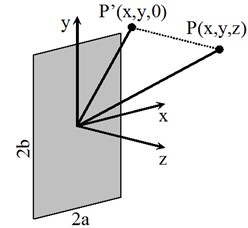
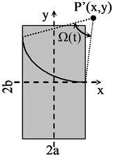
Let us consider a rectangular transducer long and () wide and located in plane (Fig. 1).
Fig. 1Geometry and coordinate system for calculation of the impulse response of a rectangular transducer
a)
b)
The impulse response function depends on time , spatial coordinates of the point , the sound velocity in a medium, the obliquity factor corresponding to the transducer boundary conditions and the angle , subtended at the point (Fig. 1(b)) by the arc, as in Eq. (1):
The obliquity factors are given in the time domain, as in Eq. (2):
When the transducer vibrates at the velocity in a liquid or gas type medium with the density , then the transient pressure at the point is calculated using convolution operation (). The distance dependent attenuation in air is estimated by calculating the attenuated impulse response function . Then the inverse Fourier transform is applied to the calculated impulse response function in the frequency domain , multiplied by the attenuation function , as shown in Eq. (3):
For the calculation of the air attenuation see references [11, 16].
If an infinite isotropic film is excited by an incident time harmonic signal, which exerts pressure over a finite radius circular region, then normal displacements in the film can be calculated using the Time Harmonic Solution (THS) method [11, 17]. Because of the THS method complexity we shall not analyze it in more detail. In short, the explained solution assumes that a Continuous Wave (CW) is used. For the transient signal the forward Fourier transform is applied and finite set of harmonic excitation frequencies is obtained. Normal displacements are computed by using a harmonic summation method.
In “The Lamb Matlab toolbox” software tool a finite excitation zone is divided into circular sub-regions of radius . The pressure signal is calculated at the centre point of a circular sub-region and taken equal in all sub-region area. The radius should be small, at least four times smaller than the minimum Lamb wavelength. Total normal displacement signal at the given point on a film is obtained by superposition of normal displacements, created by all circular sub-regions.
3. Numerical investigation using simplified 2D approach
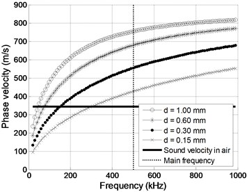
Numerical investigation has been performed simulating air-coupled Lamb wave mode excitation in a clear polyvinyl chloride (PVC) film. A square ultrasonic transducer and simplified 2D approach were used (Fig. 2). Four different PVC thicknesses have been chosen: 1, 0.6, 0.3 and 0.15 mm. The mode phase velocity dispersion curves were calculated using SAFE (Semi Analytical Finite Element) method (Fig. 3).
Fig. 2Schematic diagram of air-coupled Lamb wave excitation using transducer T
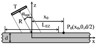
Fig. 3Phase velocity dispersion curves for A0 mode in clear PVC films of thickness d
The optimum incidence angle is calculated according to the Snell’s law, as in Eq. (4):
where is the sound velocity in air, 343 ms-1; is the Lamb wave phase velocity. From the Snell’s law follows that air-coupled excitation is not feasible when (Fig. 3), so the 500 kHz main frequency has been chosen. The calculated optimum incidence angles for different film thickness are given in Table 1.
Table 1A0 mode phase velocities and optimum incidence angles at 500 kHz main frequency
PVC thickness (mm) | mode phase velocity (ms-1) | Optimum incidence angle (°) |
1.00 | 754.6 | 27.1 |
0.60 | 678.4 | 30.4 |
0.30 | 554.2 | 38.3 |
0.15 | 426.6 | 53.6 |
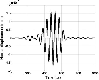
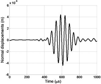
The square transducer used for excitation has dimensions 18×18 mm and is located at the distance 30 mm from the excitation zone centre on the film surface and deflected by the optimum incidence angle (Fig. 2). The length of x-line type excitation zone is set to 40 mm, the zone is filled with 201 circular sub-regions of the 0.1 mm radius. The rigid baffle obliquity factor 2 was estimated in the simulations. The transducer surface radiates a particle velocity signal of 5 cycles harmonic pulse with the sinus type envelope, 500 kHz main frequency, 1 ms-1 amplitude and 100 MHz sampling frequency. The pulse bandwidth has been limited to (303-950) kHz (Fig. 4). The normal displacements pulse of the Lamb wave mode is calculated at the point , situated on the plate’s surface at 21 mm distance from the excitation zone centre (Fig. 5 is for 1.00 mm and Fig. 6 is for 0.15 mm).
Fig. 4Transducer T velocity signal: main frequency 500 kHz, bandwidth (303-950) kHz
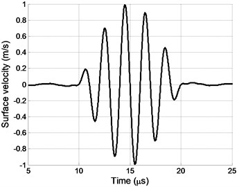
Fig. 5Normal displacements pulse at the point P0 using transducer T when d= 1.00 mm

Fig. 6Normal displacements pulse at the point P0 using transducer T when d= 0.15 mm
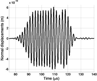
Fig. 7Normal displacements pulse duration dependency versus PVC film thickness d
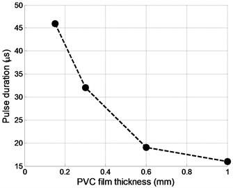
It was observed, that the pulse duration grows up when the PVC film thickness is decreased (Fig. 7).
If there is a demand on excitation of mode in the case , a new method is proposed. It is based on application of an air-coupled planar phased array with rectangular radiators, were the array pitch is equal to the Lamb wavelength in a PVC film: (Fig. 8).
Fig. 8Principle of air-coupled Lamb wave excitation using phased array with rectangular radiators and delayed excitation
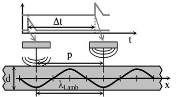
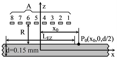
Fig. 9Schematic diagram of air-coupled Lamb wave excitation using phased array A and simplified 2D modelling approach
By exciting array elements by suitable delayed signals, summation of vibrations in the film is achieved. The delay time is given by:
The phased array pitch and the delay times are determined by the mode phase velocity and the wavelength (Fig. 10) at the selected frequency. The main frequency of 20 kHz has been chosen, where the wavelength of the mode is 4.7 mm. The phased array (Fig. 9) consists of 8 rectangular elements with dimensions of 2×15 mm and 2.7 mm space between elements. It is located at the distance 1 mm from the excitation zone centre on the film surface. The array element surface radiates a particle velocity signal of 5 cycles sinus pulse with the sinus type envelope (Fig. 11). Impulse of normal displacements at the point has been calculated for two cases. In the first case (Fig. 12) no delays for array elements have been used. In the second case (Fig. 13) delay time for each element has been increased by the step 50.2 µs, calculated according to Eq. (5).
Fig. 10A0 mode wavelength dependency versus frequency for PVC d= 0.15 mm
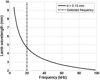
Fig. 11Array element velocity signal: the main frequency 20 kHz, the bandwidth (10-30) kHz
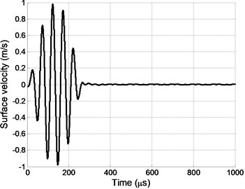
Fig. 12Impulse of normal displacements at the point P0; no delays for array A elements
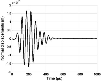
Fig. 13Impulse of normal displacements at the point P0; delays between array A elements were used
4. Numerical investigation using full 3D approach
Numerical investigation, using simplified 2D approach, is a quite fast method to obtain a normal displacements signal at one selected point on the film surface, generated by -line type excitation zone. In order to evaluate pressure and normal displacements signals distributions at selected rectangular zones on the film surface, a full 3D modeling has been performed for the same phased array (Fig. 14). Rectangular excitation and displacements calculation zones are located on a clear PVC film surface. The length of the excitation zone is set to 40 mm, the width is 20 mm, the zone is filled with 1236 circular sub-regions of the 0.4 mm radius. The length of the calculation zone is set to 30 mm, the width is 30 mm. The zone is divided into points using a square grid with 1 mm step.
Signals of pressure at the excitation zone and signals of the Lamb wave mode normal displacements at the calculation zone have been calculated for two cases. Then maximum positive peak values has been taken and plotted. In the first case (Figs. 15, 16) no delays for array elements have been used. In the second case (Figs. 17, 18) delay time for each array element has been increased by the step 50.2 µs, calculated according to Eq. (5).
Fig. 14Schematic diagram of air-coupled Lamb wave excitation using phased array A and 3D approach
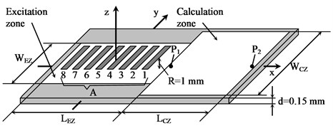
Fig. 15Distribution of pressure maximum positive peak value at excitation zone. No delays for array A elements
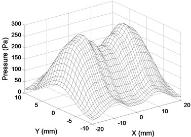
Fig. 16Distribution of normal displacements maximum positive peak value at calculation zone. No delays for array A elements
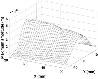
Fig. 17Distribution of pressure maximum positive peak value at excitation zone. Delays between array A elements were used
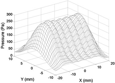
Fig. 18Distribution of normal displacements maximum positive peak value at calculation zone. Delays between array A elements were used
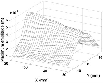
Distribution of the pressure maximum positive peak value at the excitation zone has 2 peaks when the array elements are excited simultaneously (Fig. 15), and 7 peaks when delays for elements are applied (Fig. 17). Distributions of the normal displacements maximum positive peak value at the calculation zone have almost the same shape in both cases; however delays give greater normal displacements values (Fig. 18), when compared to the simultaneous excitation (Fig. 16).
Two points have been selected at a calculation zone for comparison of normal displacements signals in the time domain. The points have been picked from the grid, generated by the program. The point (20.5, –0.5, /2) represents the location nearest to the array and -axis. The point (49.5, –0.5, /2) represents the location farthest to the array and nearest to -axis. Impulses of normal displacements signals when all elements are excited simultaneously are displayed in Figs. 19, 20 and when delays are applied in Figs. 21 and 22.
Fig. 19Impulse of normal displacements at the point P1; no delays for array A elements
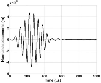
Fig. 20Impulse of normal displacements at the point P2; no delays for array A elements
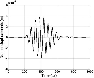
Fig. 21Impulse of normal displacements at the point P1. Delays between array A elements were used
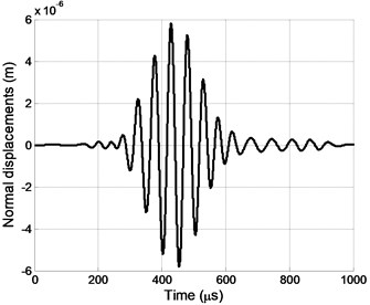
Fig. 22Impulse of normal displacements at the point P2. Delays between array A elements were used
In both cases the amplitude of normal displacements signals decreases, when the distance from the array increases. Using delays between the array elements affects the shape of the signal in the time domain – clear trails are visible at the beginning and at the end (Figs. 21, 22).
5. Conclusions
Air-coupled generation of Lamb wave mode in clear PVC plastic films has been investigated.
The excitation according to the Snell’s law is feasible for phase velocities . The simplified 2D simulation showed that decreasing of the film thickness increases the duration and the maximum amplitude of the mode impulse.
The excitation according to the Snell’s law is not feasible for phase velocities . A new method based on application of a planar phased array has been proposed for mode excitation.
The simplified 2D simulation showed that the new method eliminates the effect of significantly increased mode pulse duration, which has been observed in thin plastic films.
The full 3D simulation demonstrated distributions of pressure and normal displacements maximum positive peak values in rectangular zones. Analysis of the mode time domain signals revealed that delays between array elements have influence on the impulse amplitude and shape: the amplitude increases, but trails at the beginning and the end of the pulse emerge.
References
-
Kim D., Cho Y., Lee J. Assessment of wall-thinning in carbon steel pipe by using laser-generated guided wave. Nuclear engineering and technology, Vol. 42, Issue 5, 2010, p. 546-551.
-
Wu Y., de Labachelerie M., Bastien F. Investigations on excitation and detection methods for Lamb wave sensors. Sensors and Actuators A, Vol. 100, 2002, p. 214-222.
-
Ferrari R. M. G. The acoustoelastic effect: EMAT excitation and reception of lamb waves in pre-stressed metal sheets. Excerpt from the Proceedings of the COMSOL Conference, Milan, 2009.
-
Pettersson T., Anttila J. On the verification of the applicability of the orthotropic plate wave theory to paper. Ultrasonics, Vol. 39, 2002, p. 617-622.
-
Kažys R., Demčenko A., Žukauskas E., Mažeika L. Air-coupled ultrasonic investigation of multi-layered composite materials. Ultrasonics, Vol. 44, 2006, p. 819-822.
-
Kažys R., Demčenko A., Mažeika L., Šliteris R., Žukauskas E. Air-coupled ultrasonic non-destructive testing of aerospace components. Insight, Vol. 49, Issue 4, 2007.
-
Yañez Y., Garcia-Rodriguez M., Garcia-Hernandez M. J., Salazar J., Turo A., Chavez J. A. Lamb wave generation with an air-coupled piezoelectric concave array using square-wave burst excitation. NDT&E International, Vol. 41, 2008, p. 292-299.
-
Raisutis R., Kazys R., Zukauskas E., Mazeika L. Ultrasonic air-coupled testing of square-shape CFRP composite rods by means of guided waves. NDT&E International, Vol. 44, 2011, p. 645-654.
-
Dobie G., Spencer A., Burnham K., Gareth Pierce S., Worden K., Galbraith W., Hayward G. Simulation of ultrasonic lamb wave generation, propagation and detection for a reconfigurable air coupled scanner. Ultrasonics, Vol. 51, 2011, p. 258-269.
-
Masmoudi M., Castaings M. Three-dimensional hybrid model for predicting air-coupled generation of guided waves in composite material plates. Ultrasonics, Vol. 52, 2012, p. 81-92.
-
Prego-Borges J. L. Lamb: a simulation tool for air-coupled Lamb wave based ultrasonic NDE systems. Ph.D. dissertation, Dept. Elect. Eng., Spain, Polytechnic Univ. of Catalonia, Barcelona, 2010.
-
Prego-Borges J. L. The Lamb Matlab® toolbox. First release, beta version 0.1, 2010,
-
http://www.mathworks.com/matlabcentral/fileexchange/28367-the-lamb-toolbox.
-
Reibold R., Kažys R. Radiation of a rectangular strip-like focussing transducer. Part 1: harmonic excitation. Ultrasonics, Vol. 30, Issue 1, 1992, p. 49-55.
-
Reibold R., Kažys R. Radiation of a rectangular strip-like focussing transducer. Part 2: transient excitation. Ultrasonics, Vol. 30, Issue 1, 1992, p. 56-59.
-
San Emeterio J. L., Ullate L. G. Diffraction impulse response of rectangular transducers. J. Acoust. Soc. Am., Vol. 92, Issue 2, 1992, p. 651-662.
-
Benny G., Hayward G. Beam profile measurements and simulations for ultrasonic transducers operating in air. J. Acoust. Soc. Am., Vol. 107, Issue 4, 2000, p. 2089-2100.
-
Pavlakovic B. N., Rose J. L. The influence of finite-size sources in acousto-ultrasonics. NASA Contractor Report 195374, 1994.
About this article

