Abstract
Design and investigation of active piezoelectric block, having a precise V-shaped groove for checking the roundness or concentricity of precise shafts is presented. Piezoelectric -block realizes the rotation and translational motion of the precise shaft and is characterized by zero base errors of motion generation system. Numerical modeling based on finite element method is performed to find resonant frequencies and modal shapes of the piezoelectric actuator. The trajectories of the contacting points for shaft – piezoelectric actuator is defined. Results of numerical and experimental studies are presented.
1. Introduction
Piezoelectric motors are used in designing positioning systems for various applications ranging from advanced manufacturing to IC industry, material science, biotechnology, etc. [1-4]. This research covers development of piezodrive devoted to novel high precision angular positioning system containing conventional glass-chromium or potential low-cost polymeric-based scales [5, 6].
Active supports and bearings are based on the concept of active kinematic pairs, which covers whole range of multi-degree-of-freedom kinematic pairs, with one or both links made from active (e.g. piezoelectric) material. Active kinematic pairs enable to:
• Control the number of degrees-of-freedom of the kinematic pairs by means of friction force control in the contact zone or generation static or quasi-static deformations of the element of the pair;
• Generate forces and moments in the contact zones;
• Effect additional functions – self-diagnostics, multi-functionality, adaptivity, self-assembly;
• Implement two levels of degree-of-freedom. The first level comprises large deflections or displacements, produced by transformation of resonance oscillations of pair’s links into continuous motion. The second level deals with small displacements (in nanometre range), implemented by means of direct piezoelectric effect and specific sectioning of electrodes.
Important feature of active support is that it has zero processing datum surface errors, and can be widely used in precise measuring and manufacturing systems. Some examples of Active supports and bearings are given in [7-9].
2. Design and operating principle of piezoelectric V-block
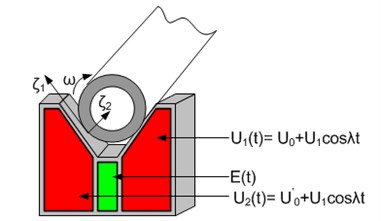
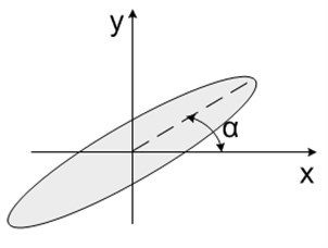
A fixture is a device used to locate, clamp, and support a work piece during machining, assembly, or inspection. Fixture error is generally considered to be one of the crucial factors in optimal fixture design and analysis [10, 11]. The major purpose of the V-blocks is to position precise shafts or cylindrical pieces to establish precisely the axis of a cylindrical piece or geometrical errors of its external surface. In our case -block is made from active material – disk of piezoceramics with sectioned electrodes and -groove to position shaft. The poling vector is perpendicular to the surface of the -block (Fig. 1). Transformation of high frequency resonant oscillations in the contact areas with the shaft enable to effect rotation of the shaft and (or) simultaneous translation along its axis. The special position of the shaft in small displacement range can be controlled by variation of and (Fig. 1), while reverse of the motion is realized by connecting harmonic signals to corresponding electrodes of the transducer.
It is possible to obtain information on the condition of the contact shaft – piezoelectric transducer by selecting special section of the electrode and analyzing the signal (Fig. 1). Specific components of its spectrum contain the information about the tribological interactions of contact surfaces and can be used to determine wear, as related to interactions between surfaces or quantitative surface roughness.
Translation of a shaft along its axis is realized by mounting V-block in relation to shaft’s axis with small deviation from angle, equal to 90º (from 80º to 85º). In this case it is possible to scan the surface of the shaft and measure the errors of its cylindrical surface. In this simplest case the reverse of the motion is impossible.
Fig. 1The schematics of piezoelectric V-block to support and rotate the shaft
The values of material’s (piezoceramics and steel) characteristics, which were used in calculations, are given in the Table 1.
Table 1The properties of the material used for modelling
Material properties | Piezoceramics PZT-23 | Steel |
Young's modulus N/m2 | 8.2764×10¹⁰ | 117×109 |
Poisson's ratio | 0.33 | 0.33 |
Density kg/m3 | 7600 | 8900 |
Dielectric permittivity × 103 F/m | 1.2; 1.2; 1.1 | |
Piezoelectric matrix × 10-3 C/m2 | -13.6; -13.6; 27.1; 37.0; 37.0 | |
3. Results of numerical modeling
Numerical modeling of piezoelectric actuator is performed to validate actuator design and operating principle through the modal and harmonic response analysis. FEM software ANSYS 11.0 is employed for simulation and FEM models are built. Material damping is assumed in the finite element model. No structural boundary conditions are applied. For the digital simulation only the relevant part of the real model is chosen, which is sufficient to get the necessary result. During analysis the angle of groove is changed. The range of angle control, used in the finite element model modal analysis, is from 70º to 100º (at 10º interval). Modal analysis of piezoelectric actuator is performed to find proper resonance frequency. While examining results of modal analysis, it is determined with which frequencies and different angles the same eigenform of oscillations are obtained.
Harmonic response analysis is performed with the aim to find out the actuator’s response to sinusoidal voltage, applied on electrodes of the piezoceramic transducer (Fig. 4). The study is aimed to find out what value of angle is optimal.
In Fig. 5 the extent of cos are represented on excitation in a contact zone (Fig. 4a), at different angle (70; 80; 90; 100).
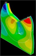
Fig. 3Finite element model of the piezoelectric actuator and vibration mode of the actuator at a) 51,7 kHz (β – 70o), b) 53,6 kHz (β – 80o), c) 52,8 kHz (β – 90o), d) 53,5 kHz (β – 100o)
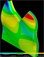
a)
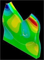
b)
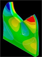
c)
d)
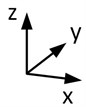
Fig. 4Determination of contact points and angles used in calculations a) contact points on the rib to which calculations of motion trajectories were carried out b) global V-block scheme: determination of the angle between the V-block rib and the edge of the shaft on excitation at contact points on the rib; determination of angle of the groove c) determination of the angle α, when the contact points on the rib are moving in elliptical trajectory
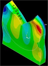
a)
b)
c)
Fig. 5The value of the cosα (Fig. 4(b)), Fig. 4(c) between the V-block rib and the edge of the shaft on excitation at contact points (Fig. 4(a)) on the rib, at different angles β of the groove (Fig. 4(b))
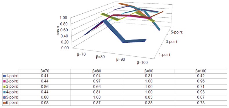
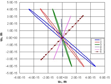
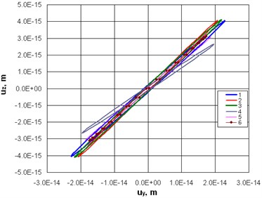
Fig. 6 illustrates these trajectories at frequency 52,8 kHz respectively. It can be seen that trajectories in both graphs have elliptic shape, but ratio of the major and minor axis are different. Analyzing ratio between major and minor axis of the ellipsis it can be indicated that peak of the ratio appears at resonant frequency. It means that trajectories of motion are close to straight line at resonance and oscillations close to standing wave type are achieved.
By observing elliptical trajectories and their parameters, it can be concluded that trajectories of contact point have opposite directions at different frequencies. It means that slider has direct and reverse motion at these frequencies.
Analyzing ellipsis parameters at axis , bigger ratios are at 6th and 5th points, while at axis bigger ratios are at 6th, 5th and 4th points.
Fig. 6Trajectories of the contact point motion in: a) Ux, Uz, b) Uy, Uz axes direction (resonant oscillations are obtained at 52,8 kHz)
a)
b)
Fig. 7Experimental model of V-block
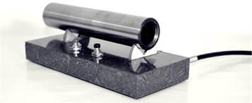
Fig. 8Rotation speed of precise shaft in relation to frequency
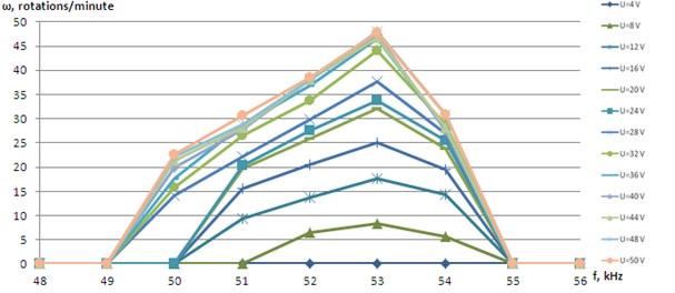
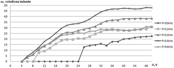
Fig. 9Rotation speed of precise shaft in relation to voltage
4. Experimental study
Experiments are performed with a model, shown in Fig. 7, allowing to effect reverse of motion and angular speed control by changing the amplitude and frequency of harmonic signal. As can be seen in Fig. 8, maximum angular speed is obtained at 53 kHz and the range of controlling the speed is relatively large – from 49 kHz to 55 kHz respectively, depending on applied voltage (Fig. 9).
5. Conclusions
Piezoelectric V-block for checking the roundness or concentricity of precise shafts are designed and investigated. The modeling and experimental studies indicate that it can be applied for positioning and actuating of shafts or cylindrical pieces to establish precisely the axis of a cylindrical piece or geometrical errors of its external surface.
After the completion of studies it turned out that pressing the roller additionally from the top, more optimal rotation would be obtained.
In many fields of application, vibromotors solve the problems of positioning and uniform high-speed displacements, and execute prescribed motions. Mechanism with controllable structure and mechanism with controllable parameters are also very effective.
Recently results have shown that current project relating to multidegrees of freedom piezoelectric vibromotors will constitute a minor step for the future development of micromanipulators and microrobots. To provide a microrobot with both transportation and micromanipulation capabilities, various designs of future motors can be used.
For instance, piezoelectric V-block could be applied in high positioning engines, mechanisms of printer heads, or laser shutters.
References
-
Liu T. Y., Wang W. C. A self-moving precision positioning stage utilizing impact force of spring-mounted piezoelectric actuator. Sensor and Actuators A: Physical, 2002, Vol. 102, Issues 1-2, p. 83-92.
-
Kuo M. W., et al. Precision nano-alignment system using machine vision with motin controlled by piezoelectric motor. Mechatronics, 2008, Vol. 18, Issue 1, p. 21-34.
-
Zeng J., Salton A., Fu M. Design and control of a rotary dual-stage actuator positioning system. Mechatronics, 2011, Vol. 12, Issue 1, p. 1003-1012.
-
Gao W., Sato S., Arai Y. A linear-rotary stage for precision positioning. Precision Engineering, 2010, Vol. 34, Issue 2, p. 301-306.
-
Bansevičius R., Grybas I., Janušas G., Lazauskas A., Malinauskas K. Application of incremental polymeric scales for high precision piezoelectric angular positioning system. Journal of Vibroengineering, 2012, Vol. 14, Issue 3, p. 1215-1219.
-
Kim S. H., Cho M. Y. Design and modeling of a novel 3-DOF precision micro-stage. Mechatronics, 2009, Vol. 19, Issue 5, p. 598-608.
-
Bansevicius R., Ahmed S. Bearings and Supports. USA Patent 6,262,514, July 2001.
-
Bansevicius R., Ahmed S. Drive Mechanism. GB Patent 2 332 090, April 2001.
-
Bansevicius R., Ahmed S. Piezoelectric Active Supports. GB Patent 2 331 398, February 2001.
-
Pat Nugent Form Measurement Fundamentals. Mahr Federal, 5 April 2008.
-
Hui Wang, Qiang Huang Error cancellation modeling and its application to machining process control. IIE Transactions, ISSN 0740-817X, Vol. 38, 2006, p. 379-388.
About this article

This research is funded by the European Social Fund under the project “Microsensors, microactuators and controllers for mechatronic systems (Go-Smart)” (Agreement No. VP1-3.1-ŠMM-08-K-01-015) and Lithuanian Science Council, Project No. MIP-075/20.
