Abstract
Computation model of crankshaft was built and the dynamic characteristics of crankshaft were studied. FEM was performed to obtain the maximum main stress, the minimum main stress and the Mises stress at three kinds of critical working conditions of crankshaft. Through movement analysis and computation for various components of reciprocating mud pump (RMP), the loads of crankshaft were obtained. The maximum stress of crankshaft at the three kinds of dangerous operating modes was obtained from the FEM stress analysis. It is located in the critical region and the location belongs to the dangerous position in most of the fracture crankshafts. The FEM stress analysis results are very valuable in guiding actual application development for intelligence optimization design of RMP.
1. Introduction
RMP are widely used for pumping viscous liquids and oil wells. It is designed to circulate drilling fluid under high pressure down the drill string and back up the annulus. Liquid is taken from one end and positively discharged at the other end for every revolution [1]. In recent years, because of the development of petroleum well drill and oil extraction technology, RMP had further enhancement in the performance and other aspects. In order to adapt to many kinds of working conditions, in the structure, material and manufacturing of RMP have appeared new changes. The high efficiency RMP may prevent the drill rod blocking, eliminate the rock debris of well bottom, reduce the well drill cycle and cost, and thus it has deserved special attention in many nations. The power and depth of drill are increasing and the promotion ability is also strengthening. The high pressure RMP is also developing to high efficiency, high speed, high precision, large power, low cost, saving resource and high performance. Therefore enhancing the security, reliability and performance of high pressure and high efficiency RMP is the effective way for the well drill benefit.
Crankshaft is a large and important component with a complex geometry in the RMP. It transforms the rotary motion into the line motion and endures very big alternation stress and torque.Its design, optimization and manufacturing affect the operating performance of RMP. Mechanics of materials is applied in traditional crankshaft calculation and the accuracy of calculated results is not high because of many simplifications and hypotheses. So the larger safety factor is adopted [2-4]. In order to avoid larger construction size and material waste, the loads of crankshaft should be extensively studied and new analysis tool should be applied. Dynamic load methods combined with FEM were used to analyse the crankshaft of combustion engine and reciprocating compressor [5-10]. The FEM was also successfully applied to scroll compressor design [11, 12]. Ye Xiao-Yan et al. built an analytic model for fatigue reliability of crankshaft [13]. The fatigue reliability of crankshaft model is analyzed in detail by using the radius vector method. Shi Wei-Dong et al. developed an application program which can realize design and analysis of crankshaft [14]. However for the crankshaft of RMP no complete model that includes all of the detailed dynamic computation has been published so far.
This paper developed a detailed computation model of crankshaft. Through movement analysis and computation for various components, the loads of crankshaft were obtained. Then FEM was applied to three kinds of selected dangerous working conditions of crankshaft and satisfying results were obtained. The results are regarded as a theory basis to optimize the design of crankshaft and for the analysis of the structure dynamics of crankshaft. It enhances design initiative and accuracy, speeds up renewal speed, improves performance, saves manpower and cost, and offers a new method for the development of high pressure, large power, high efficiency and high performance RMP.
2. The computation model and dynamic loading analysis
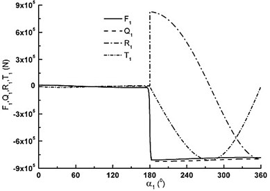
RMP is the key component in oil well engineering. The RMP consist of two main sub-assemblies, the fluid end and the power end. Fig. 1(a) is the structure of RMP. It is made up of big herringbone gear, crankshaft, connecting rod, crosshead, shell, intermediate rod and the fluid end et al. Fig. 1(b) is the fluid end. Fig. 1(c) is the crankshaft. The power end is a typical crank-link mechanism. The power is passed to connecting mechanism through big herringbone gear. The crankshaft is driven by big herringbone gear. Then rotary motion is transformed into line motion by the crankshaft. The liquid flow generated by this reciprocating motion is directed from the pump inlet (suction) to the pump outlet (discharge) by the selective operation of self-acting check valves located at the inlet and outlet of each displacement element. Suction and discharge power of the fluid end for oil well liquid and this makes oil well liquid circulation. The process is repeated continuously. In Table 1 are the basic parameters of RMP.
Fig. 1The structure of RMP: 1. RMP power end, 1-1. Big herringbone gear, 1-2. Crankshaft, 1-3. Connecting rod, 1-4. Crosshead, 1-5. Shell, 1-6. Intermediate rod; 2. The fluid end, 2-1. Suction tube, 2-2. Discharge tube
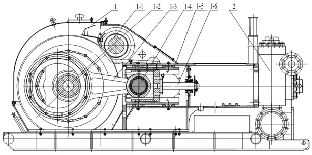
a) The structure of RMP
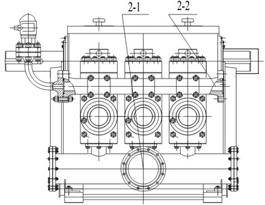
b) The fluid end
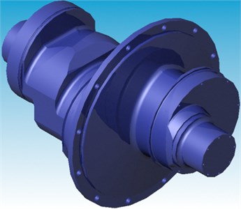
c) Crankshaft
Table 1The basic parameters of RMP (the triplex reciprocating mud pump)
Parameter | Value |
Rated input power | 1600 HP |
Rated frequency of stroke | 120 min-1 |
Piston stroke | 305 mm |
Rated speed of driving shaft | 518 r∙min-1 |
The maximum working pressure | 35 MPa |
Displacement | 1.84 m3∙min-1 |
The crankshaft experiences complex loading due to the motion of the connecting rod, which transforms loads to the crankshaft. The main objective of the computation model is to determine the accurate magnitude and direction of the loads that act on the crankshaft over the entire working cycle, which are then used in the FEM. Fig. 2(a) is computation model of slider-crank mechanism with a single degree of freedom. Crankshaft angles 0°~180° and 180°~360° are defined as suction process and discharge process respectively.
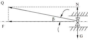
Fig. 2(b) is forces acting on crosshead. Horizontal component of can be passed to piston rod. So horizontal component of crosshead is given by:
where is the force acting on piston rod under suction process. is the force acting on piston rod under discharge process. is the weight of crosshead assembly. is friction coefficient. is angle of and . is inertia force.
Connecting rod force is defined by the following expressions:
where is mechanical efficiency of connecting rod bearing. is the ratio of crank radius and connecting rod length.
Fig. 2c) is the forces acting on crank. Components and of are defined as follows:
Axial force of the big herringbone gear is given by:
where is crank radius. is cylinder diameter. 1, 2 and 3 represent different cranks respectively.
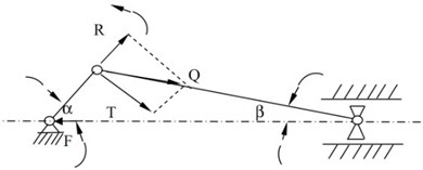
Fig. 2d) is the crankshaft computation model. A and B are the bearing supports. Moving coordinates XYZ are fixed in crankshaft and rotate with it.
Fig. 2The resolution of forces and computation model
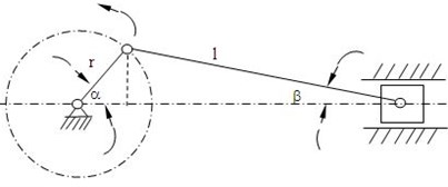
a) Computation model of slider crank mechanism
b) Forces acting on crosshead
c) Forces acting on crank
d) The crankshaft computation model
Counterforces of A supporting are given by:
Counterforces of B supporting are given by:
where , , , , and are distances. is the weight of crankshaft excluding three eccentric wheels. is the weight of the eccentric wheel and connecting rod. is the centrifugal force of . is the angle of section III-III and acting plate of . The positive value of calculation results indicates the same direction with coordinate axes. Negative value indicates opposite direction.
Usually the crankshaft with large section change will cause large stress. So three sections I-I, II-II and III-III are selected as dangerous sections for stress analysis.
(1) Internal force of I-I section
Moving coordinate system is fixed in crankshaft and rotates with crankshaft. Shearing force of I-I section is given by:
The bending moment of I-I section is given by:
(2) Internal force of II-II section
Moving coordinate system is fixed in crankshaft and rotates with crankshaft. The bending moment of II-II section is given by:
(3) Internal force of III-III section
Moving coordinate system is fixed in crankshaft and rotates with crankshaft. Shearing force of III-III section is given by:
The bending moment of III-III section is given by:
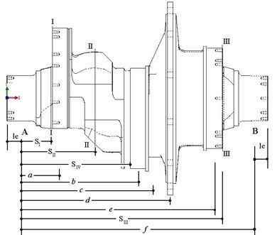
The load computation of entire crankshaft model is based on 3 pistons working ability. According to the entire RMP working parameters, the loads of different parts can be gotten at different positions. Through the loads of crosshead, connecting rod, piston rod et al. and inertia force analysis, the final crankshaft load results were obtained. Fig. 3a), b) and c) show the forces variation of piston rod, connecting rod and crank.
Fig. 3The forces of piston rod, connecting rod and crank
a) The forces of crank throw I
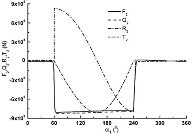
b) The forces of crank throw II
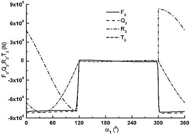
c) The forces of crank throw III
Fig. 4The loads of crankshaft assembly
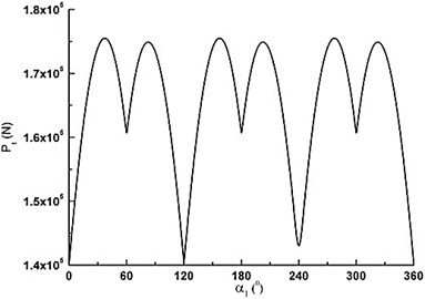
a) Tangential force of big herringbone gear
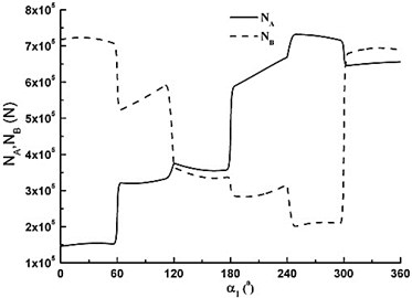
b) Counterforces of A and B supports
c) Torque of crankshaft
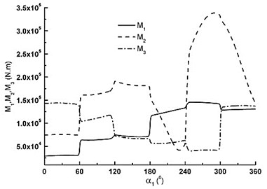
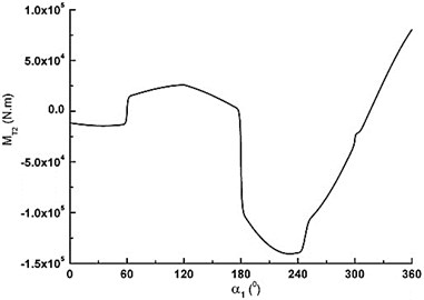
d) Bending moments of crankshaft
As can be seen in Fig. 3a), is very small from 0° to 180° because there is the inhalation process of piston. As degree increases it is very big and declines during the range of 180° to 360°. has the same discipline with piston rod. and are very small from 0 to 180°. changes from maximum pull to maximum pressure in the range of 180° to 360° with cosine change. first decreases, then increases according to sine change. For the three crank throws, the forces are of the same change, but they have different phases. Fig. 4(a) is tangential force variation of big herringbone gear. repeats the same cycle every 60°. The maximum is about 1.8×10⁵ N. The minimum is about 1.4×10⁵ N. Fig. 4(b) is counterforces variation of A and B supports. When 30°, the maximum of B supporting is about 7.2×10⁵ N. When 245°, the maximum of A supporting is about 7.3×10⁵ N. Fig. 4(c) is torque of crankshaft. Fig. 4d) is the total bending moment variation of crankshaft for three dangerous sections. The loads results are the base of FEM analysis.
3. FEM stress analysis of crankshaft
3.1. The FEM analysis
The Pro/E is used as engineering tool to implement the geometry generation. A virtual crankshaft model is developed according to the inherent characteristics of RMP. Solid model has emerged as a superb tool for component design, especially when there is added value in linking geometry to various forms of structure, thermal, kinematic, and dynamic, et al. It is more important that solid model can be used as a powerful tool to bridge the gap between the designer and the manufacturing engineer. The created solid model is the foundation for FEM analysis. In Table 2 are the crankshaft material properties.
Table 2Crankshaft material properties
Material properties | ZG25MnVCu |
Elasticity modulus | 175 GPa |
Poisson ratio | 0.3 |
Density | 7.85×10⁻⁶ kg/mm3 |
Expansion coefficient | 1.33×10⁻⁵ /°C |
Heat transfer coefficient | 0.0498 W/mm °C |
Specific heat | 470 J/kg °C |
Tensile strength | 509 MPa |
Fatigue strength | 313 MPa |
Since the crankshaft has a complex geometry for analysis, FEM stress analysis have been considered to give an accurate and reasonable solution. Based on the obtained loads and the three dangerous sections analysis, the three most unfavorable operating modes were selected. The solid model of crankshaft was input to ANSYS. The proper boundary conditions were appointed according to the structure and motion characteristics. The stress distribution of the crankshaft was computed through FEM analysis under three kinds of dangerous states: 105°, 300° and . The maximum main stress, the minimum main stress and the Mises stress of were firstly analyzed.
Fig. 5a) is the restraints of crankshaft. Supporting is simplified into cylindrical hinge restriction. In order to constrain the axis movement, the end section of B supporting is fixed. Because the model can’t revolve, the loads of three crank throws and big herringbone gear are decomposed in the current reference frame and added on the solid analysis model according to coordinate axis. Loads and moments of big herringbone gear and three crank throws are defined. Bearing force and moment are added on corresponding crank throws according to different load style. The Fig. 5b) and c) are moments and forces acting on crankshaft under 300.
Fig. 5The loads acting on crankshaft under α1= 300°
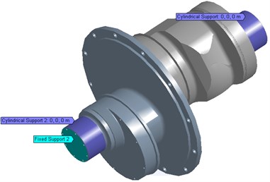
a) The constrains of crankshaft
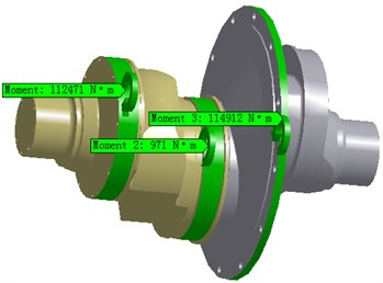
b) The moments of crankshaft
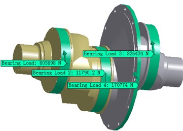
c) The forces of crankshaft
3.2. Analysis and discussion of computed results
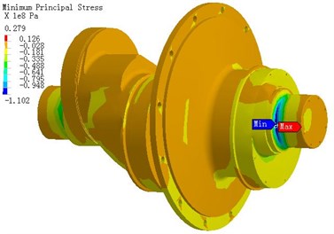
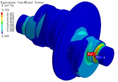
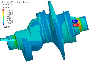
Using the FEM analysis the stress distributing of crankshaft due to working loads was obtained, which is useful for improving the quality of optimization, manufacturing and assembly accuracy. The computed results of the maximum main stress, the mininimum main stress and the Mises stress under 300° are shown in Fig. 6. The maximum pull stress 93.7 MPa appears as close to crankshaft right end (the maximum is marked in the Fig. 6(a)). The other side of crankshaft bearing stress is 45 MPa. The maximum stress of two positions is caused by bend deformation. The bend deformation is restricted because the cylindrical hinge restraints are set at the two ends of bearing and thus it causes high bend stress. The stress in middle crankshaft which is caused by bend deformation and torsion is not high because of bigger section area. Fig. 6(b) is the minimum main stress distribution of crankshaft. Similar with the maximum stress, the minimum main stress which is caused by bend is high at the two ends of bearing. The maximum pressure stress -83.55 MPa appears at the right flank root of III crank throw (the minimum is marked in Fig. 6(b)). Fig. 6(c) is the Mises stress distribution of crankshaft. The maximum Mises stress 75.88 MPa appears at right root of bearing (the maximum is marked in Fig. 6(c)), and where is also the maximum pull stress position. Under 300°, the stress of entire crankshaft is extremely non-uniform and the stress of minority spots is high. The maximum pull stress is 93.7 MPa. The maximum pressure is -83.55 MPa and the maximum Mises stress is 75.88 MPa. Using the same method the crankshaft stress was calculated under 105° and 360°.
Fig. 6The stress distribution of crankshaft under α1= 300°
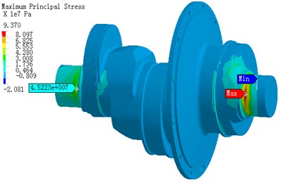
a) The maximum main stress distribution
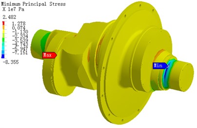
b) The minimum main stress distribution
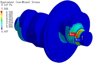
c) The Mises stress distribution
Fig. 7The stress distribution of crankshaft under α1= 105°

a) The maximum main stress distribution
b) The minimum main stress distribution
c) The Mises stress distribution
Fig. 8The stress distribution of crankshaft under α1= 360°
a) The maximum main stress distribution

b) The minimum main stress distribution

c) The Mises stress distribution
Fig. 7 is the stress distribution of crankshaft under 105°. Under 105° the entire crankshaft stress is higher, the maximum pull stress 109 MPa appears as close to crankshaft right end (the maximum is marked in the Fig. 7(a)). The maximum pressure stress is -110 MPa (the maximum is marked in the Fig. 7b)), and the maximum Mises stress is 97.4 MPa (the maximum is marked in Fig. 7(c)). The maximum stress is caused by bend deformation. The bend deformation is restricted because the cylindrical hinge restraints are set at the two ends of bearing and thus it causes high bend stress.
Fig. 8 is the stress distribution of crankshaft under 360°. Under 360° the entire crankshaft stress is not high. The maximum pull is 67 MPa. The maximum pressure is -68 MPa and the maximum Mises stress is 53 MPa.
The stress has the almost same distribution for the three kinds of operating modes. The maximum stress is located in the fillet region because of high stress gradients in the location which result in high stress concentration factors, and the location belongs to the dangerous position in most of the broken crankshafts. But all stresses are lower than the bend limit and permission stress of material. Finally the accurate analysis results provide the theory basis for structure design and the material re-choice of the crankshaft. Through FEM analysis computation the weight of crankshaft is reduced above 10 % based on the original foundation.
4. Conclusions
(1) Computation model of crankshaft was built. The load results of the three dangerous sections were obtained through dynamics loading analysis of components.
(2) Three kinds of dangerous operating modes: 105°, 300° and 360° were computed using FEM stress analysis. The maximum main stress, the minimum main stress and the Mises stress distribution were obtained. The maximum main stress is 109 MPa. The minimum main stress is -110 MPa. The maximum Mises stress is 97.4 MPa. But all of those stresses are lower than the bend limit and permission stress of material. The stress induced by bending moment is almost 4 times than by torsional load.
(3) Critical locations on the crankshaft are located on the fillet areas because of high stress gradients in these locations which result in high stress concentration factors.
(4) The FEM analysis was effectively applied to design crankshaft. The analysis results of the stress distribution provide the theory basis for the intelligent optimization design of RMP.
References
-
Reciprocating Pump Design Compilation Group. Reciprocating Pump Design, China Machine Press, Beijing, 1987, (in Chinese).
-
Huang Shiqiao Analysis. method of dynamics on reciprocating pump. Chemical Engineering & Machinery, Vol. 15, No. 5, 1988, p. 272-275, (in Chinese).
-
Zhu Yong-You, Ye Yong-Biao, Zhou Rong, Zhang Wei. The kinematics and dynamics analysis of sludge pump. General Machine, Vol. 5, 2005, p. 65-67, (in Chinese).
-
Feng Ping-Fa, Sheng Li, Wu Zhi-Jun, Yu Ding-Wen. Study on the dynamic load and mechanical property of the plunger pump crankshaft. Machinery Design & Manufacture, Vol. 5, 2007, p. 155-157, (in Chinese).
-
Lee H. J. Dynamics and probabilistic fatigue analysis schemes for high-speed press machines. Computers & Structures, Vol. 50, No. 1, 1994, p. 11-19.
-
Xu Wei-Guo, Huang Rong-Hua, Zhao Miao-Sen, Zuo Zhao-Feng, Wang Xing-Guang. New calculation method of crankshaft fatigue strength. Chinese Internal Combustion Engine Engineering, Vol. 25, No. 5, 2004, p. 51-55, (in Chinese).
-
Zhou Xun, Yu Xiaoli, Li Ying. Investigation for the residual strength degeneration regular of crankshaft serving on steady fatigue load. Chinese Journal of Mechanical Engineering, Vol. 42, No. 4, 2006, p. 145-151, (in Chinese).
-
Montazersadgh F., Fatemi A. Dynamic load and stress analysis of a crankshaft. SAE Technical Paper 2007-01-0258, 2007, p. 1-8.
-
J. A. Becerra, F. J. Jimenez, M. Torres, D. T. Sanchez, E. Carvajal. Failure analysis of reciprocating compressor crankshafts. Engineering Failure Analysis, Vol. 18, No. 2, 2011, p. 735-746.
-
Jian Meng, Yongqi Liu, Ruixiang Liu. Finite element analysis of 4-cylinder diesel crankshaft. I. J. Image, Graphics and Signal Processing, Vol. 3, No. 5, 2011, p. 22-29.
-
Z. Jiang, D. K. Harrison, K. Cheng. Computer-aided design and manufacturing of scroll compressors. Journal of Materials Processing Technology, Vol. 138, No. 1, 2003, p. 145-151.
-
Chiachin Lin, Yuchoung Chang, Kunyi Liang, Chinghua Hung. Temperature and thermal deformation analysis on scrolls of scroll compressor. Applied Thermal Engineering, Vol. 25, No. 11-12, 2005, p. 1724-1739.
-
Ye Xiao-Yan, Jiang Xiao-Ping, Xu Jian-Qiang, Shi Wei-Dong. Fatigue reliability analysis on crankshaft of reciprocating pump. Chinese Journal of Mechanical Engineering, Vol. 44, No. 10, 2008, p. 272-276, (in Chinese).
-
Shi Wei-Dong, Jiang Xiao-Ping, Xu Jian-Qiang, Ye Xiao-Yan, Hu Jing-Ning. Development and application of design program for crankshaft of reciprocating pumps. Journal of Jiangsu University, Vol. 30, No. 3, 2009, p. 279-283, (in Chinese).
About this article

This work was supported by National Natural Science Foundation of China (Grant No. 51275226), Natural Science Foundation of Zhejiang Province (Grant No. LY12E05010), Scientific Research Foundation for the Returned Overseas Chinese Scholars of Gansu Province (Grant No. 1002ZSB114), Natural Science Foundation of Gansu Province (Grant No. 1112RJZA003), Fundamental Research Funds for the Gansu Province Universities (Grant No. 1202ZTC057) of China.
