Abstract
This article presents results of investigation of piezoelectric transducer which consists of rectangle homogeneous piezoceramic plate with two additional masses glued on the top surface of the transducer. Because of additional masses and a certain sectioning of piezoelectric electrodes, the vibration forms of the plate and resonant frequencies are changed, therefore, the plate generates 3D longitudinal and bending vibrations. Numerical and experimental investigation showed that the masses glued at the surface of piezoelectric plate obtain elliptical trajectories of motion when the first mode of longitudinal vibrations of the plate is excited. Such form of vibrations of the masses enables using them for various piezoelectric drive mechanisms as contact elements and to transform high-frequency vibrations into the directional or rotational movement of the rotor or slider. In order to examine the deformations and dynamic characteristics of the homogenous piezoelectric plate with two additional masses, the numerical modelling of such piezo transducer and the experimental study have been carried out.
1. Introduction
Piezoelectric actuators are widely used in very precise positioning equipment as for example in optic mirrors or microscopes positioning mechanisms, scanners, cameras etc. Also, piezoelectric transducers are used for excitation or suppression vibrations of mechanisms for instance vibration suppression of the hard disk drives. [1, 2] Piezoelectric actuators have such advantages as nano-metric scale resolution, high speed and high holding forces [3]. Depending on the number of active layers, plate-type piezoelectric actuators of bending deformations are classified into bimorphs (two layers of piezoelectric ceramics are installed), unimorphs (a single layer of piezoelectric ceramics is used which is glued to the layer of the other material) and multi-layered actuators [4-9]. The bending vibrations of such actuators are obtained because of elongation of piezoelectric layer i.e. characteristic of piezoceramic is employed [10].
This investigation analyses the rectangular plate type transducer of a single piezoelectric ceramics layer with two additional masses attached on the top surface of the transducer. It is a new idea enabling the simplification of the generation of 3D bending vibrations in a piezoelectric plate. At the moment, the bending vibrations are generated in the plate only after the realisation of piezoelectric bimorph, i.e. by using additional passive or active piezoelectric ceramic plates [9, 10]. According to the modelling results, the additional masses fitted in certain areas of the piezo plate change the forms of its vibrations and resonant frequencies. The results of the experiments showed that the first mode of longitudinal vibrations have been excited in a piezoelectric plate when a certain sectioning of electrodes is used. If two additional masses are attached on certain areas of one lateral surface of the plate, then contact points of these masses move in the elliptical trajectory. In order to examine the deformations and dynamic characteristics of the homogenous piezoelectric plate with two additional masses, the mathematical modelling and experimental study have been carried out.
2. Principle design of piezoelectric homogeneous plate with additional masses
Configuration of transducer includes homogeneous PZT-4 piezoceramic plate and two steel spheres as the masses that are glued at the top surface of the plate (Fig. 1(a)). Dimensions of the piezoceramic plate is 45×15×3 mm. Polarization vector of piezoceramic is oriented along thickness of the plate (Fig. 1b). Electrodes are located at the top and the bottom surface of the piezoceramic plate. Top surface electrodes are divided into four equal sections while bottom electrode is grounded (Fig. 1(b)).
Operating principle of the actuator is based on using multimode vibration of the plate i.e. the first mode of longitudinal resonant vibrations in y direction and the second mode of bending resonant vibrations in direction (Fig. 1(a)). With the help of additional masses 8 attached in certain areas of piezo ceramic plate 4 at the same time bending mode vibrations are exited in direction as well. Superposition of the first longitudinal mode in direction and the second flexural mode in the direction is used to obtain elliptical trajectories of additional mases 8 in the plane (Fig. 1(a)). This piezoelectric transducer can be used in various piezoelectric mechanisms and to transform high-frequency vibrations of the plate into directional movement of the slider or rotation of the rotor. Electrode pattern allows is used to realize direct and reverse motion of the contact points of the steel spheres (Fig. 1(b)). The oscillation amplitudes in and directions can be increased by increasing the voltage of harmonic control signal .
Fig. 1Homogeneous plate with two additional mases. Here: 1, 2, 3 – electrodes, 4 – piezo ceramic plate, 5, 6, 7 – longitudinal and bending vibrations in x, y and z directions, 8 – additional mases, U – control signal
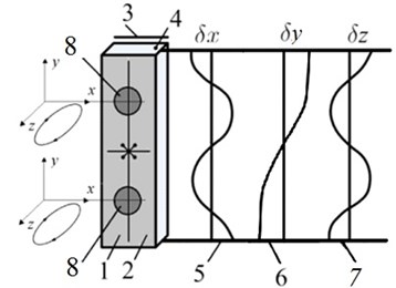
a) Operating principle
b) Excitation scheme
3. Numerical modelling and analysis
Finite element was used to confirm and validate operation principle of the proposed piezoelectric actuator. Numerical study included modal frequency analysis and harmonic response analysis. Motion trajectories of the top points of the additional masses were calculated as well. FEA software Ansys 15.0 was used to build a three-dimensional finite element model of the actuator and to run simulation. The model contains PZT-4 piezoceramic plate and two steel hemispheres were used as additional masses (Fig. 2(a)). Dimensions of the plate were 45×15×3 mm. Diameter of the both steel spheres was set to 4 mm. Electrodes of the plate were divided into four equal sections as it is shown in Fig. 1(b). No mechanical boundary conditions were applied in the model. Modal-frequency analysis of the actuator was performed and the modes with the dominated first longitudinal mode and second in-plane bending mode were found at 36.31 kHz and 38.58 kHz respectively (Fig. 2(b)). Then harmonic response analysis was performed when 50 V sinusoidal electric signal was applied. Excitation scheme of the electrodes was used as shown in Fig. 1(b). A frequency range from 35 kHz to 40 kHz with a solution at 200 Hz intervals were investigated and adequate response curves of contact point’s oscillation amplitudes were calculated. The graph of the first contact point’s amplitude versus the frequency is given in Fig. 3(a). It can be seen that resonant frequencies were obtained at 36.60 kHz and 39.0 kHz. Operation modes of the plate at the given frequencies correspond the modal shapes described earlier.
Fig. 2Results of numerical modelling: 1 – piezoelectric plate; 2, 3 – additional masses
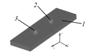
a) Model of the actuator
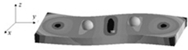
b) Modal shape at 38.58 kHz
While analysing elliptical motion of the contact points in plane, it can be noticed that the lengths of the major axes are 0.58 µm to 0.995 µm at 36.60 kHz and 39.0 kHz respectively (Fig. 3(b)). The difference between lengths is 41.7 %. Also, major axes of the ellipses are rotated about the centre of the coordinate system by the different angles and depend on excitation frequencies of the actuator. This can be explained because of difference in modal shapes that are actuated at these resonant frequencies. The velocity of the contact point’s motion is higher at 39.0 kHz, while impact of the contact point is more powerful when excitation frequency is 36.60 kHz.
Fig. 3Results of harmonic response analysis
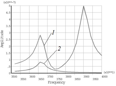
a) Contact point oscillation amplitude versus frequency: 1 – direction, 2 – direction
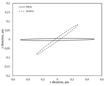
b) Trajectories of contact point motion in plane
4. Experimental results
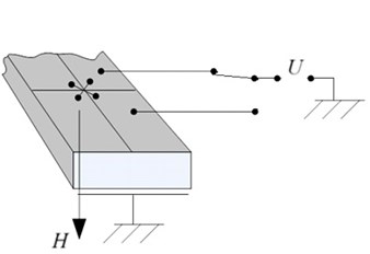
The deformation of the piezoelectric plate in plane, the frequency response and motion trajectories of additional masses have been measured by using Polytec scanning vibrometer (model PSV-F-500-3D-HV) (Fig. 4). This vibrometer has three laser heads that have been used to scan the piezoelectric plate and to measure the vibrations of its surface in , and directions [11].
The results of experimental measurements revealed the shape of piezoelectric plate vibrations and the frequency response of its contact points vibrations in and direction of coordinate axes (Figs. 5-6). According to the obtained results, in case of 37.4 kHz frequency, the second-mode bending vibrations are excited in and directions, when the contact points obtain maximum movement trajectories.
The trajectories of the contact point motion obtained during the experimental measurements are close to the trajectories obtained during the numerical modelling, however, the elliptical trajectories generated by the first and second mass are not identical (Fig. 7). Such non-compliance of the motion of additional masses may be the result of the errors of experimental prototype manufacturing, inaccurate properties of the piezoelectric material, asymmetry of vibrations and the influence of the environment during the experiment.
Fig. 4Experimental set up
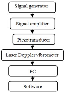
a) Structure scheme
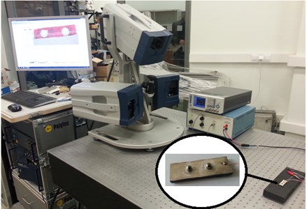
b) Stand view
Fig. 5Deformation of the plate in xz plane

Fig. 6Frequency response of contact points: 1 – in x direction, 2 – in z direction
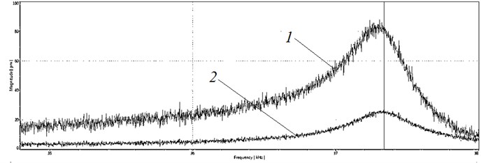
Fig. 7Trajectories of the contact points motion in xz plane (37.4 kHz)
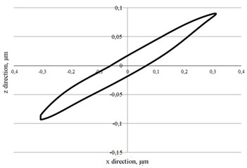
a) First mass
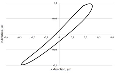
b) Second mass
In order to determine the deformations of the examined homogeneous piezo plate with additional masses in the direction, the holographic vibration and deformations measurement system PRISM 100 (Hytec Inc., USA) has been used [12]. Fig. 8 presents the holographic images of the piezoelectric plate when the plate was excited with harmonic electric signal of the amplitude of 50 V and frequency of 37.4 kHz. Dark holographic lines visible by the attached additional masses show the asymmetric nature of deformations of the piezo plate when the control signal is provided to one (Fig. 8(a)) and another group of electrodes (Fig. 8(b)).
Based on the results of the experimental study, it can be concluded that the masses attached to the lateral area of the piezo plate move in elliptical trajectories in and directions as presented in Fig. 7, whereas the direction of the motion is changed by connecting the control signal to different electrodes of the piezo plate. Such form of vibrations of these masses enables their use in various piezo drives as contact driving elements.
Fig. 8Holographic view of homogeneous plate (37.4 kHz, 50 V). Here 1 – piezo ceramic plate, 2 and 3 – additional masses
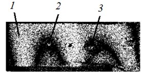
a) Excited the first section of electrodes
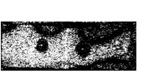
b) Excited the second section of electrodes
RB conceived the concept of active kinematic pairs and participated in design of the investigated homogeneous plate using additional masses. SN and VJ carried out the experimental investigations: optical measurements and visualization of vibrations of the investigated device and drafted the manuscript. DM and AŽ conducted numerical investigation of dynamics of the piezoelectric plate with additional masses. All authors read and approved the final manuscript.
5. Conclusions
This paper presents the results of the numerical modelling and experimental study of homogenous piezoelectric transducer. Numerical and experimental studies confirmed that bending vibrations of the piezoelectric plate in direction can be obtained by employing additional masses. Results of the harmonic response analysis showed that the contact points located on the top of the masses of piezoelectric transducer generate the elliptical trajectories in plane and its resonant frequencies are 36.6 kHz and 39 kHz in and directions. Experimental study revealed frequency response and motion trajectories of the movement of additional masses which are close to the obtained results of the numerical modelling. The established insignificant inadequacies of these results may be the result of the errors of the production of experimental sample, the properties of used piezoelectric material, asymmetry of vibrations and the influence of the environment during the experiment. The experimental test has shown that the plate is deformed in respect of and axes and its resonant frequency is 37.4 kHz when the contact elements obtain maximum movement trajectories.
References
-
Qiu Z., Pulskamp J. S., Lin X., Rhee C. H., Wang T., Polcawich R. G., Oldham K. Large displacement vertical translational actuator based on piezoelectric thin films. Journal of Micromechanics and Microengineering, Vol. 20, Issue 7, 2010, p. 1-10.
-
Chu L. L., Gianchandani Y. B. A micromachined 2D positioner with electrothermal actuation and sub-nanometer capacitive sensing. Journal of Micromechanics and Microengineering, Vol. 13, Issue 2, 2003, p. 279-285.
-
Borrelli N. F. Microoptics Technology: Fabrication and Applications of Lens Arrays and Devices. Second Edition, Marcel Dekker Inc., New York, 1999.
-
Yoo J. H., Hong J. I., Cao W. Piezoelectric ceramic bimorph coupled to thin film metal plate as cooling fan for electronic devices. Sensors and Actuators A: Physical, Vol. 79, 2000, p. 8-12.
-
Banerjee J. R., Sobey A. J. Further investigation into eigenfrequencies of a two-part beam-mass system. Journal of Sound and Vibration, Vol. 265, 2003, p. 899-908.
-
Yamada K., Matsuhisa H., Utsuno H. A new method for accurately determining the modal equivalent stiffness ratio of bonded piezoelectric structures. Journal of Sound and Vibration, Vol. 331, Issue 14, 2012, p. 3317-3344.
-
Parashar S., Das Gupta A., Von Wagner U., Hagedorn P. Non-linear shear vibrations of piezoceramic actuators. International Journal of Non-Linear Mechanics, Vol. 40, 2005, p. 429-443.
-
Sitti M., Campolo D., Yan J., Fearing R. Development of PZT and PZN-PT Based Unimorph Actuators for Micromechanical Flapping Mechanisms. Constant Magnet Motors, USA, 2001.
-
Ivan I. A., Rakotondrabe M., Lutz P., Chaillet N. Quasistatic displacement self-sensing method for cantilevered piezoelectric actuators. Review of Scientific Instruments (RSI), Vol. 80, 6, p. 2009-65102.
-
Linnan Z., Zhi-fei S. Analytical solution of a simply supported piezoelectric beam subjected to a uniformly distributed loading. Applied Mathematics and Mechanics, Vol. 24, Issue 10, 2003, p. 1215-1224.
-
Sylwester S., Wojciech S., Andrzej T., Marek C. Application of 3-D laser scanning vibrometer in determination of free vibration frequencies of composite plates with damage. Solid State Phenomena, Vol. 240, 2016, p. 42-48.
-
Rickert T., Fix R., Suominen L. Comparison of Residual Stress Measurements Using X-Ray Diffraction and PRISM-Electronic Speckle Pattern Interferometry and Hole-Drilling (No. 2007-01-0804). SAE Technical Paper, 2007.
About this article

The work was supported by the Research Council of Lithuania under the Projects PiezoDeflect No. MIP-045/2014 and OptoControl No. TEC-02/2015.
