Abstract
Rigid Frame Bridge was widely used while the according seismic design was quite difficult and worth of discussion. Section sizes of piers were increased when elasticity seismic theory was adopted; plastic hinges were designed on the top or bottom of piers when ductility seismic theory was employed; and isolation bearings were installed when seismic isolation theory was applied. However, larger size may neither be cost-effective nor meet the requirements of seismic design. Furthermore, seismic rehabilitation would be extremely difficult when plastic hinges were employed, and isolation bearings were not applicable to Rigid Frame Bridge as there was nowhere to place them. A new method was proposed for Rigid Frame Bridge referred as base-isolation design. Based on introducing base-isolation concept, base-isolation design of Rigid Frame Bridge was achieved by setting seismic-isolation layer in cap. There were four kinds of base-isolation systems widely adopted in numerical investigation of base-isolation for Rigid Frame Bridge, i.e., laminated elastomeric bearings (EB) system, lead rubber bearings (LRB) system, EB and liquid viscous dampers (EB-LVD) system, and LRB-LVD system. It was found that: i) seismic effect transmitted to superstructure and substructure of bridge could be dramatically reduced by seismic-isolation layer; ii) efficiency of base-isolation system could be significantly promoted by using EB and LVD together; iii) mechanical parameters of isolation devices should be determined according to the actual situation of the bridge.
1. Introduction
Two types of connections between beam and pier, i.e., bearing connection and rigid connection, were widely adopted in Beam Bridges in recent decades [1, 2]. The former was normally used in Continuous Beam Bridge, while the latter was more often employed in Rigid Frame Bridge. Seismic design of Continuous Beam Bridge and Rigid Frame Bridge were not the same mainly due to the diversity of the connections. Generally, isolation bearings could be used to improve seismic performance of Continuous Beam Bridge by relieving the vibrations between superstructure and substructure of bridges. There were many kinds of isolation bearings applied to Continuous Beam Bridge, such as laminated elastomeric bearings (EB), lead rubber bearings (LRB), high damping rubber bearings (HDR), friction pendulum system bearings (FPS), shape memory alloy bearings (SMA), etc. [3-7]. Seismic response of Continuous Beam Bridge could be dramatically reduced by using isolation bearings reasonably [8, 9]. However, isolation bearings were not applicable to Rigid Frame Bridge due to space limitations. For Rigid Frame Bridge, there were two feasible ways to meet demands of seismic design: increasing section sizes of bridge components and setting plastic hinges on the top or bottom of piers. On one hand, larger size may neither be cost-effective nor meet the requirements of seismic design. On the other hand, plastic hinges could effectively decrease seismic response of Rigid Frame Bridge, but seismic rehabilitation would be extremely difficult. Considering spanning capacity and advantages in eliminating the need for large tonnage bearing, it was necessary to study new method to improve seismic performance of Rigid Frame Bridge.
Base-isolation was a mature and effective technology in building seismic design by setting isolation layer on the bottom of building. Effectiveness of base-isolation in buildings had been verified by experiments, theoretical analysis, and actual earthquakes [10-12]. However, its application in bridges was not fully developed yet. In bridge design, base-isolation was applied to Rion-Antition Bridge, which was a multi-span cable-stayed bridge in Greece [13]. Foundation was directly placed on a 3-meter thick layer of gravel in this bridge, so movements between the both parts were separated and seismic isolation was achieved. Analogously, base-isolation might be a good way to solve seismic design of Rigid Frame Bridge.
In this paper, the concept of base-isolation was applied to Rigid Frame Bridge. A 180 m Rigid Frame Bridge embedded with isolation layer inside bridge cap to mitigate seismic vibrations was introduced. A parametric study was conducted using calibrated finite element models of Rigid Frame Bridge to investigate the effects of EB and liquid viscous dampers (LVD) on seismic design. It was found that seismic effect delivering to superstructure and substructure of bridge could be dramatically reduced by seismic-isolation layer. Efficiency of base-isolation could be significantly increased by using EB and LVD together. Mechanical parameters of isolation devices should be determined according to the actual situation of the bridge.
2. Base-isolation of rigid frame bridges
A new type of base-isolation, with isolation layer set inside bridge cap, was developed for Rigid Frame Bridge. The isolation layer was made up by isolation devices, including EB, LRB and LVD. Mechanical properties of these isolation devices were described below to better understand the predominant seismic performance. A typical Rigid Frame Bridge was introduced as the object of study, and overview of the bridge was described afterwards.
2.1. Base-isolation configuration
Base-isolation originated from building seismic, the concept of which was setting an isolation layer between foundation and superstructure of building so as to separate the movement between superstructure and horizontal component of ground motion. The isolation layer was composed of seismic isolation devices, such as isolation bearings and dampers. Isolation bearings with appropriate elastic restoring force could stably continuously support the weight and follow the horizontal deformation of building. Dampers could be used to absorb seismic input energy. When suffered to a rare earthquake, the horizontal force acting on superstructure of base-isolation building was much smaller than that of general building, making it easier to design the superstructure by elasticity theory.
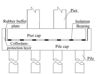
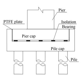
Bridges components from top to bottom were superstructure, substructure, and foundation as shown in Fig. 1. Foundation was located on ground. It can be seen that there were three basic types of connection in bridges, i.e., connection between superstructure and substructure, connection between substructure and foundation, and connection between foundation and ground. The first type of connection included bearing connection and ridge connection. The second connection usually employed consolidation connection. The third connection was achieved by soil-structure-interaction (SSI). Traditional seismic isolation design of bridge was dedicated to the study of bearing devices, especially for the isolation bearings, which were proved unsuitable for Rigid Frame Bridge as there was nowhere for installation. Meanwhile, SSI was not fully resolved yet due to the complicated configurations, so the third connection was not suitable for seismic isolation of Rigid Frame Bridge either. According to the principle of seismic isolation, connection between substructure and foundation could be used for seismic isolation of Rigid Frame Bridge as there was adequate space to place isolation devices.
Consolidation connection was adopted between pier and foundation (cap) for Rigid Frame Bridge, and it should be changed to active connection to apply base-isolation design. However, “top-heavy” was an important feature of bridge, which meant that the sizes of bridge piers were relatively small. From the point of view to enhance the overall stability of the bridge, it was unsuitable to set up isolation devices at pier bottom. Therefore, a new way in this paper was presented to achieve base-isolation by splitting cap into two parts and setting up isolation devices between both conponents as an isolation layer (see Fig. 1). Pier cap, substructure and superstructure were compiled and connected into a whole, while pile cap and pile were bonded together. Cofferdam-protection layer was fixed in the outside of pile cap to prevent too large longitudinal seismic displacement of bridge. Rubber buffer plate was stuck in the inside of cofferdam-protection layer. PTEE plate was installed in transverse direction to release the longitudinal movement during earthquake and to maintain lateral seismic performance during ordinary use.
Fig. 1Configuration of base-isolation layer: a) longitudinal direction, b) transverse direction
a)
b)
2.2. Base-isolation devices
Lots of isolation bearings were adopted as connections between superstructure and substructure, while the mature and safe ones should be chosen for base-isolation. In this paper, EB and LRB were used as isolation bearings for Rigid Frame Bridge. Meanwhile, LVD were employed to limit too large earthquake displacement of bridge during earthquakes.
Fig. 2Configuration of EB
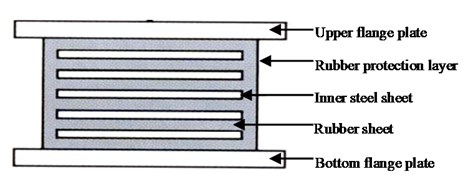
EB, as shown in Fig. 2, was interleaved by thin rubber sheets and steel sheets. Horizontal stiffness and vertical stiffness of EB were determined by Eqs. (1) and (2) separately:
where was shear modulus of rubber, was effective horizontal shear area of EB, and was the total depth of rubber layer and:
where was modified compression elastic modulus of rubber, was effective compression area of EB, and was the total depth of rubber layer.
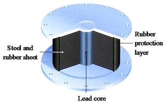
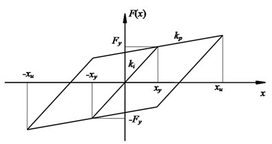
LRB shown in Fig. 3(a) was made by inserting a piece of lead core in EB. The lead core provided energy dissipation capacity under earthquake and yield strength under static loads. When subjected to lower horizontal force, deformation of LRB was rather small because of the high initial stiffness, while the lead core turned to yield during earthquake to dissipate energy and extend the period of bridge by reducing stiffness.
Hysteresis curve of LRB shown in Fig. 3(b) was given by analytical data. Bilinear type was adopted for hysteresis curve, and it was widely used in the analysis of LRB. Unloading stiffness was employed when the load effecting on LRB was smaller than yield load, and post-yielding stiffness was employed when the load effecting on LRB exceeded yield load. The analysis of a nonlinear model was proposed in [14]. The structural nonlinearity was described by the following formulas:
where was post-yielding stiffness, was shear stiffness of an EB with the same overall dimensions, was unloading stiffness, was yield load, was area of lead core, was area excluding the area of lead core, was total area of LRB, and D was diameter of lead core.
Fig. 3Characteristics of LRB: a) configuration, b) hysteresis curve
a)
b)
Fig. 4Characteristics of LVD: a) configuration, b) hysteresis curve
a)
b)
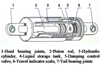
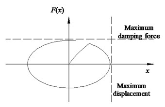
LVD shown in Fig. 4(a) was composed of cylinder, piston and fluid. Piston with a small hole in the middle could do reciprocating movement in the cylinder equipped with fluid damping material. LVD had many advantages such as excellent energy dissipation capacity, easy installation and maintenance, less impact of the excitation frequency and ambient temperature.
Relationship between damping force and relative velocity of LVD was determined by Eq. (7):
where was damping force; was damping coefficient; was relative velocity between two ends of LVD; α was damping index in the range of 0.1 to 2.0, from a seismic point of view, the common value of α was generally in the range of 0.2 to 1.0. Hysteresis curve of LVD was shown in Fig. 4(b), and the hysteresis loop represented the energy dissipation.
2.3. A Rigid Frame Bridge example
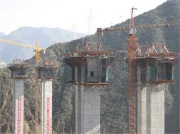
A pre-stressed concrete Rigid Frame Bridge with span arrangement of 98 + 180 + 98 = 376 m was shown in Fig. 5. Single cell box-section was adopted in girder of the bridge. Girder height varied by 1.8 times parabola, which was 11.0 m in middle fulcrum, and 4.0 m in the middle of main span. Roof width of box girder was 12.0 m, and bed width of box girder was 6.5 m. Dual thin-walled hollow pier was used, with the height of 68.0 m and 70.0 m respectively. Hollow box section was chosen for piers, with outer contour size of 7.5 m in transverse direction and 3.5 m in longitudinal direction. Rectangular cap and pile foundation were employed as foundation of the bridge.
Fig. 5Photos of a pre-stressed concrete Rigid Frame Bridge during different construction stage: a) the zero block construction stage, b) the closure up construction stage of the main span
a)
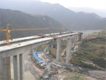
b)
Fig. 6Seismic input: a) response spectrum, b) acceleration history
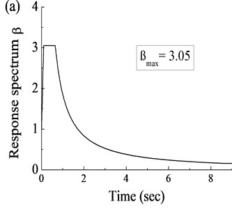
In each cap, there were a total of 12 piles, each of which was 2.5 m in diameter and 40.0 m in length. Geological conditions in the site of bridge were described as an overburden layer of clay and silty clay distributing within depth of 5.0 m below pile cap, and strongly weathered tufflava and in weathering tuff lava below the overburden layer in order. The Rigid Frame Bridge was located in high intensity seismic region. Seismic input shown in Fig. 6 was applied to the target bridge structure longitudinally for seismic analysis in this paper. The response spectrum, as shown in Fig. 6(a), was designed by the local code especially according to the actual site of the target bridge. Hence, the acceleration history (see Fig. 6(b)) was generated from the response spectrum and applied to the finite element (FE) model as the response input.
3. Seismic analysis
Finite element model of the Rigid Frame Bridge example was developed to determine seismic performance of base-isolation. Four kinds of base-isolation systems were adopted to find out the most suitable way of using base-isolation. EB-LVD system was proved to be a better base-isolation system for Rigid Frame Bridge through analysis, and a parametric study was performed to examine the influence of various parameters on the efficiency of base-isolation system for Rigid Frame Bridges. Finally, seismic performance of base-isolation Rigid Frame Bridge was studied using the chosen parameters.
3.1. Finite element model
Isolation layer of Rigid Frame Bridge was made up by isolation devices. Four kinds of base-isolation systems were obtained by using EB and LRB alone, or in conjunction with LVD, which contained EB system, LRB system, EB-LVD system, and LRB-LVD system. In practice, isolation bearings, types of which were determined by reaction force of the end of pier cap, were evenly arranged in longitudinal and transverse direction. There were 35 sets of base-isolation systems installed in each cap for this Rigid Frame Bridge.
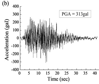
Fig. 7Dynamic analysis model of a Rigid Frame Bridge
A detailed finite element model of base-isolation was developed using MIDAS/Civil [15] to determine the static and dynamic performance for Rigid Frame Bridges as shown in Fig. 7. In the FE model, beams, piers and piles were simulated by space beam elements containing 504 units, SSI was solved by equivalent linear spring, and base-isolation systems were simulated as actual position and performance. Parameters of isolation devices used were as follows: for EB, = 2.8 kN/mm, = 1106 kN/mm; for LRB, = 12.3 kN/mm, = 1.9 kN/mm, = 523 kN; for LVD, = 500 kN/(m/s)0.5, = 0.5.
3.2. Finite element analysis
Calculation results of seismic response of Rigid Frame Bridge under different base-isolation systems were summarized in Table 1. Ordinary seismic system (OSS), the case without base-isolation, was chosen as a reference for comparative analysis. Efficiency feature parameter of base-isolation system, was defined as below:
where was the value of seismic response of OSS, was the value of seismic response of base-isolation systems.
Table 1Results of seismic response under different base-isolation systems
Seismic response | OSS | EB system | EB+LVD system | LRB system | LRB+LVD system | ||||
value | (%) | value | (%) | value | (%) | value | (%) | ||
Longitudinal vibration frequency (Hz) | 0.356 | 0.262 | / | 0.262 | / | 0.323 | / | 0.323 | / |
Displacement at the end of beam (mm) | 344 | 449 | -30.5 | 263 | 23.5 | 271 | 21.2 | 312 | 9.3 |
Axial force at pier top (kN) | 23359 | 12825 | 45.1 | 7791 | 66.6 | 14266 | 38.9 | 12644 | 45.9 |
Shear force at pier top (kN) | 11848 | 7737 | 34.7 | 4887 | 58.8 | 6890 | 41.8 | 8295 | 30.0 |
Moment at pier top (kN·m) | 376862 | 271989 | 27.8 | 173194 | 54.0 | 226832 | 39.8 | 289619 | 23.1 |
Axial force at pier bottom (kN) | 23197 | 12746 | 45.1 | 7776 | 66.5 | 14371 | 38.0 | 12752 | 45.0 |
Shear force at pier bottom (kN) | 12576 | 8717 | 30.7 | 6362 | 49.4 | 7644 | 39.2 | 9090 | 27.7 |
Moment at pier bottom (kN·m) | 391435 | 297675 | 24.0 | 184539 | 52.9 | 224308 | 42.7 | 288823 | 26.2 |
Axial force of pile body (kN) | 17040 | 12405 | 27.2 | 8167 | 52.1 | 9173 | 46.2 | 12197 | 28.4 |
Shear force at pile body (kN) | 3500 | 2214 | 36.7 | 1770 | 49.4 | 2203 | 37.1 | 2333 | 33.3 |
Moment at pile body (kN·m) | 6531 | 4762 | 27.1 | 3402 | 47.9 | 4197 | 35.7 | 4676 | 28.4 |
Regarding dynamic characteristics, the following findings were observed: LVD did not change the dynamic characteristic of Rigid Frame Bridge; longitudinal vibration frequency was decreased when using base-isolation systems because of reduced longitudinal stiffness of Rigid Frame Bridge; longitudinal vibration frequency adopting LRB was larger than that of EB as unloading stiffness of LRB was much larger than horizontal stiffness of EB.
In terms of seismic displacements, it could be seen: although longitudinal stiffness of Rigid Frame Bridge was reduced by EB system, seismic displacement was relatively large because EB could not dissipate seismic energy as an elastic component; seismic displacement was significantly reduced by LVD as it could dramatically increase damping of Rigid Frame Bridge and dissipate seismic energy; seismic displacement was effectively reduced by LRB, for its strong nonlinear characteristic in energy dissipation; LVD and LRB could both dissipate seismic energy, but the effect of co-use of them was even worse as they could not work in synchronization.
As for seismic internal forces, it could be concluded as follows: four kinds of base-isolation systems could effectively reduce seismic internal forces of the key parts of Rigid Frame Bridge, and base-isolation was a good way to enhance seismic performance of bridge. Isolation efficiency of EB+LVD system was one of the best in four base-isolation systems, and next was LRB system; isolation efficiency of LRB+LVD system was not good for asynchronous working of the two devices; isolation efficiency of EB system was not good either because EB could not dissipate seismic energy during earthquake.
3.3. Parametric study
Based on the analysis above, EB+LVD system was selected as the base-isolation system for Rigid Frame Bridge. Parameter analysis was done to further clarify the impact of parameters of each component on seismic performance of Rigid Frame Bridge.
There were two basic components, EB and LVD, in the selected base-isolation system. The following parameters were examined to evaluate the parameter sensitivities: horizontal stiffness of EB, vertical stiffness of EB, damping coefficient of LVD, and damping index of LVD. Values of parameters were shown in Table 2, wherein when analysis was carried out for one parameter the other ones adopted the basic value.
Table 2List of parameter values
Name of parameter | Unit | Basic value | Variance value | |||
Horizontal stiffness | kN/mm | 2.8 | 1.4 | 2.1 | 3.5 | 4.2 |
Vertical stiffness | kN/mm | 1106 | 553 | 830 | 1383 | 1659 |
Damping coefficient | kN/(m/s)α | 500 | 200 | 300 | 800 | 1000 |
Damping index | N/A | 0.5 | 0.2 | 0.3 | 0.8 | 1.0 |
Fig. 8Effect of parameters to efficiency of base-isolation system: a) horizontal stiffness of EB, b) vertical stiffness of EB, c) damping coefficient of LVD, d) damping index of LVD
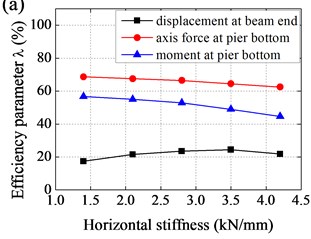
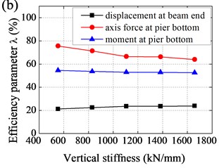
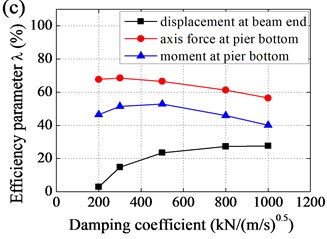
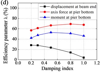
Effect of parameters to efficiency of base-isolation system was shown in Fig. 8. It could be observed that i) with horizontal stiffness increased, displacement at beam end decreased and then increased, while axis force and moment at pier bottom increased and amplification was gradually increasing; ii) with vertical stiffness increased, displacement at beam end slightly decreased, axis force at pier bottom increased and amplification was gradually decreasing, and moment at pier bottom slightly increased; iii) with damping coefficient increased, displacement at beam end decreased and amplification was gradually decreasing, while axis force and moment at pier bottom decreased and then increased, and amplification was gradually increasing; and iv) with damping index increased, displacement at beam end increased and amplification was gradually increasing, while axis force and moment at pier bottom decreased and then increased.
Effect of horizontal stiffness and vertical stiffness of EB to efficiency of base-isolation system was relatively small, the value of which should not be too small, taking into account the requirements of the static force. As a result, values of horizontal stiffness and vertical stiffness were determined as follows: 2.8 kN/mm, 1106 kN/mm. In contrast, seismic response of Rigid Frame Bridge was more sensitive to damping coefficient and damping index. In general, values of damping coefficient and damping index were determined as follows: 500 kN/(m/s)0.5, 0.5.
3.4. Seismic performance of the base-isolation system
Parametric study in conjunction with numerical comparisons regarding various base-isolation systems in Rigid Frame Bridge provided with effective base-isolation system, e.g., EB+LVD system, as well as accordingly optimized parameters. Aforementioned seismic input, especially developed for the on-situ bridge, was applied to the FE model to pursue the seismic performance of the bridge with the proposed base-isolation system and the original seismic system.
The validity of EB+LVD system in Rigid Frame Bridge was demonstrated by the hysteresis loops in Fig. 9, which eventually explained why the seismic response of bridges was reduced. Hysteresis loops represented the energy dissipation, and each circle indicated the energy dissipation in one movement cycle of the isolation system. The tilt of the hysteresis loop represented the reduction of the isolation system stiffness. It could be seen: stiffness of Rigid Frame Bridge was decreased by EB, thereby seismic internal forces were reduced; additional damping of Rigid Frame Bridge was provided by LVD, thereby seismic displacement was restrained because of energy dissipation; complete base-isolation system was obtained by combination of EB and LVD.
Fig. 9Numerical hysteresis loops for Rigid Frame Bridge using EB+LVD system
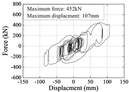
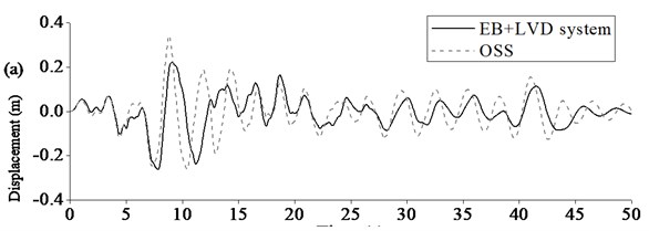
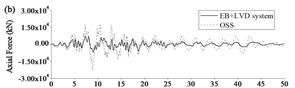
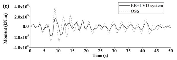
Figure 10 showed the comparison of seismic responses of Rigid Frame Bridge with EB+LVD system and original seismic system. Maximum seismic displacement at beam end could be limited to certain extent because LVD could dramatically increase damping of Rigid Frame Bridge and dissipate seismic energy. Maximum seismic internal forces of key components could be significantly decreased as EB could reduce the longitudinal stiffness of Rigid Frame Bridge and LVD could add the additional damping to the bridge further. Therefore, it was clearly proved that the base-isolation system, especially EB+LVD system could improve the seismic performance of the Rigid Frame Bridge, including displacement, axle force, negative moment, and so on.
Fig. 10Typical seismic response of Rigid Frame Bridge using EB+LVD system: a) displacement at beam end, b) axial force at pier bottom, c) moment at pier bottom
4. Conclusions
A parametric study was performed to examine the influence of various parameters, including horizontal stiffness of EB, vertical stiffness of EB, damping coefficient of LVD, and damping index of LVD, on the efficiency of base-isolation system for Rigid Frame Bridges. Based on the aforementioned base-isolation principles, overall seismic performance was compared through the parametric study. The isolation layer was determined to be installed inside the cap for Rigid Frame Bridges. The conclusions from the study are summarized as follows:
(1) Seismic response could be effectively decreased by isolation layer in order to improve the seismic performance of Rigid Frame Bridge;
(2) Efficiency of the base-isolation system was significantly improved by the combination of EB and LVD, which could, respectively, decrease the rigidity and increase the damping of Rigid Frame Bridge and work together effectively;
(3) Horizontal stiffness and vertical stiffness of EB should be determined by static analysis as they had little effect on the efficiency of the base-isolation system, while damping coefficient and damping index should be determined by parametric analysis since the seismic response of Rigid Frame Bridge was sensitive to them.
References
-
Nielson B. G., DesRoches R. Seismic performance assessment of simply supported and continuous multispan concrete girder highway bridges. Journal of Bridge Engineering, Vol. 12, Issue 5, 2007, p. 611-620.
-
Yoshikawa M., Hayashi H., Kawakita S., Hayashida M. Construction of Benten viaduct, Rigid-Frame Bridge with seismic isolators at the foot of piers. Cement & Concrete Composites, Vol. 22, 2000, p. 39-46.
-
Mori A., Carr A. J., Cooke N., Moss P. J. Compression behavior of bridge bearings used for seismic isolation. Engineering Structures, Vol. 18, Issue 5, 1996, p. 351-362.
-
Hwang J. S., Chiou J. M. An equivalent linear model of lead-rubber seismic isolation bearings. Engineering Structures, Vol. 18, Issue 7, 1996, p. 528-536.
-
Chaudhary M. T., Abe M., Fujino Y. Performance evaluation of base-isolated Yama-age Bridge with high damping rubber bearings using recorded seismic data. Engineering Structures, Vol. 23, 2001, p. 902-910.
-
Tsopelas P., Constantinou M. C., Kim Y. S., Okamota S. Experimental study of FPS system in bridge seismic isolation. Earthquake Engineering and Structural Dynamics, Vol. 25, 1996, p. 65-18.
-
Wilde K., Gardoni P., Fujino Y. Base-isolation system with shape memory alloy device for elevated highway bridges. Engineering Structures, Vol. 22, 2000, p. 222-229.
-
Park K. S., Jung H. J., Lee I. W. A comparative study on aseismic performances of base-isolation systems for multi-span continuous bridge. Engineering Structures, Vol. 24, 2002, p. 1001-1013.
-
Dicleli M. Seismic design of Lifeline Bridge using hybrid seismic isolation. Journal of Bridge Engineering, Vol. 7, Issue 2, 2002, p. 94-103.
-
Yegian M. K., Kadakal U. Foundation isolation for seismic protection using a smooth synthetic liner. Journal of Geotechnical and Geoenvironmental Engineering, Vol. 130, Issue 11, 2004, p. 1121-1130.
-
Spyrakos C. C., Koutromanos I. A., Maniatakis A. Seismic response of base-isolated buildings including soil-structure interaction. Engineering Structures, Vol. 29, 2009, p. 658-668.
-
Sorace S., Terenzi G. Non-linear dynamic design procedure of FV spring-dampers for base-isolation – frame building applications. Engineering Structures, Vol. 23, 2001, p. 1568-1576.
-
Teyssandier J. P., Combault J., Morand P. The Rion-Antition Bridge design and construction. 12th World Conference on Earthquake Engineering, 2000, Paper No. 1115.
-
Mori A., Moss P. J., Cook N., Carr A. J. The behavior of bearings used for seismic isolation under shear and axial load. Earthquake Spectra, Vol. 15, Issue 2, 1999, p. 199-224.
-
MIDAS/Civil Theory Manual. Release 8.0.5. MIDAS Information Technology Co., Ltd., 2012.
About this article

