Abstract
Taking a single-span rotor system with two discs as the research object, the pedestal looseness fault is simulated by a piecewise linear spring-damper model, and this model is combined with the FE (finite element) model of the rotor system. Two different loading conditions are determined based on API Standard 617 and the spectrum cascades, rotor orbits and Poincaré maps are used to analyze the influences of the stiffness of non-loosened bolts, looseness clearance and rotating speed on the dynamic characteristics of the system. The results show that different bifurcation forms, multiple periodic, quasi-periodic and chaotic motions can be observed under two loading conditions, and the system motion is more complicated under the second loading condition. The results will provide theoretical references for fault diagnosis, dynamic design, and safe operation of the rotor-bearing system.
1. Introduction
In the rotating machinery, the pedestal looseness is a common fault. The poor installation quality and the long-term vibration will lead to the looseness between the mechanical components. Especially, the serious looseness fault may induce other faults such as rub-impact fault between the rotor and the stator, even may lead to disastrous accidents [1]. Therefore, the research on pedestal looseness fault is significant in engineering practice for the safe operation of rotating machinery, the extension of service life and the improvement of its work efficiency.
Many researchers have studied the pedestal looseness by using piecewise linear models [2-7]. Muszynska et al. [2, 3] proposed a bi-linear model of a rotating machine with one loose pedestal. Their numerical results shows the synchronous and subsynchronous fractional components of the response, which were verified by the experiments. Chu et al. [4] analyzed the vibration characteristics of a rotor-bearing system with pedestal looseness by building a non-linear mathematical model. The stability of these periodic solutions was discussed by using the shooting method and the Floquet theory. In some cases, the pedestal looseness could result in 1/2 fractional harmonic and multiple harmonic components such as 1X/2, 2X, 3X, etc., and could occur intermittently under some special conditions [5]. Duan et al. [6] proposed a non-linear mathematical model of a rotor system with pedestal looseness, which considers both the variation of the stiffness and the periodic impact action caused by the pedestal looseness. Chen [7] introduced a dynamic model of a coupled rotor-rolling bearing-casing system considering of the coupling faults of the rotor unbalance and the pedestal looseness.
The piecewise linear models have also been proved to well simulate a discontinuous stiffness affected by a bearing clearance, rotor-stator contact, etc. Aiming at a Jeffcott rotor with a piecewise-linear non-linearity at the bearing support, Kim et al. [8] presented a multiple harmonic balance method and analyzed the internal resonant steady state vibration of the rotor system. Hossain et al. [9] studied preloading effects on the bilinear system with clearance and analyzed the nonlinear responses by the changing of the equilibrium positions for a wide range of the excitation frequency, the results show that equilibrium position is an important parameter in the bilinear system with clearance problem, which can show the chaotic and the multiple periodic motion. Considering the nonlinearity of a discontinuous stiffness affected by a radial clearance between the elastically supported rotor and an elastically supported outer ring, Gonsalves et al. [10] and Karpenko et al. [11] investigated the nonlinear vibration responses of a two degree of freedom rotor dynamic system. Aiming at a rotor system with bearing clearance and stabilizing rods, Karlberg et al. [12] presented a piecewise linear two degrees-of-freedom rotor system model and analyzed the nonlinear vibration responses of the system. Considering the effects of the piecewise stiffness and damping caused by the bearing clearance, Gao et al. [13] established a six-degree-of-freedom (DOF) model of a machine-tool spindle-bearing system and investigated the effect of bearing clearance, bifurcations and routes to chaos of this nonsmooth system.
Recently, many researchers have studied the rotor looseness fault by using the finite element method. Based on the non-linear finite element theory, Ren et al. [14] analyzed the influence of the looseness fault on the non-linear dynamic characteristics of a single-span rotor system with two discs by the simulation. Ma et al. [15] analyzed the effects of the looseness parameters on the system dynamic characteristics by using the finite element method based on the piecewise linear stiffness model. Behzad [16] developed a finite-element code for studying the effects of loose rotating discs on the vibration responses of the rotor-bearing system. The developed finite-element model can numerically give the response of rotors with any number of loose discs at any location with isotropic or orthotropic supports.
Most of previous researches on looseness fault focused on the simple Jeffcott rotor systems using the lumped mass model and only a few works were on the complex rotor system with looseness fault using finite element method (FEM). In this paper, taking a single-span rotor system with two discs as the object, the pedestal looseness is simulated by piecewise linear stiffness and damping models. And then the models are coupled with the finite element model of the rotor system. Based on the two different loading conditions, the effects of the stiffness of non-loosened bolts, looseness clearance, and rotational speed on the dynamic characteristics of the system are investigated by using the spectrum cascades, rotor orbits and Poincaré maps. The results can provide theoretic basis for the fault diagnosis of the pedestal looseness.
2. Dynamic model of a rotor system with pedestal looseness fault
2.1. Finite element model of a rotor system
In order to simulate the dynamic characteristics of the rotor system efficiently, the system is simplified according to the following assumptions:
(a) The shaft is simulated by a Timoshenko beam and the element model is shown in Fig. 1.
(b) The two oil film bearings are identical, which are simulated ideally by linear stiffness and damping models and the effects of the pedestal looseness on the stiffness and damping of the bearing are ignored.
(c) The pedestal looseness locates in the right bearing position, and the stiffness and damping between the pedestal and the base are only considered in the looseness direction.
Fig. 1Finite element model of shaft section element
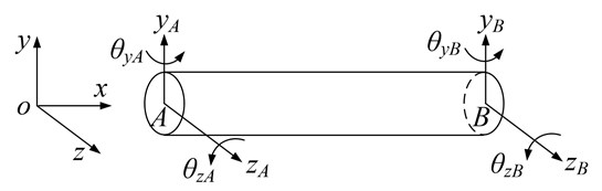
Neglecting axial and torsional deformations, the general displacement vector of a beam element for the shaft is given as:
2.2. Equivalent stiffness model of the loosened pedestal
When one or a few bolts loosen and vibration aggravates, the pedestal and the base may be separated partially. Assuming that the right pedestal looses in vertical direction ( direction), as is shown in Fig. 2. In the figure, is pedestal displacement and is the looseness clearance.
Fig. 2Bolt looseness schematic
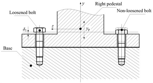
When , the pedestal contacts with the base and the equivalent stiffness of the right pedestal is the base stiffness . When , non-loosened bolts will be in a state of elastic deformation due to the pulling force and is the stiffness of non-loosened bolts . When , the loosened bolts and non-loosened bolts will be pulled together, here is ( is the stiffness of loosened bolts). Based on the above analysis, it is clear that kbr is a piecewise function related to and its expression can be written as:
Assuming that base stiffness is approximately equal to tensile stiffness of bolts, namely, , then Eq. (2) can be simplified as:
The equivalent damping of the right pedestal is similar to , and its expression is:
2.3. Finite element model of a rotor system with pedestal looseness
Considering the piecewise linear model of the right pedestal looseness [15], the non-linear equation of motion of the rotor-bearing system can be written as:
where , and denote the mass matrix, damping matrix and stiffness matrix of the whole system, respectively. The mass matrix includes the rotor mass and pedestal mass; the damping matrix includes the viscous damping (), bearing damping and gyroscopic damping; the stiffness matrix includes the rotor stiffness, bearing stiffness and equivalent pedestal stiffness. is the displacement vector and is the external load vector. In this paper, Rayleigh damping form is adopted to determine the viscous part () and it can be obtained by the following formula:
where:
Here and are the first and second critical speeds (r/min), and the corresponding modal damping ratios, respectively.
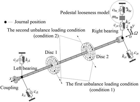
The FE model of the rotor system with pedestal looseness is shown in Fig. 3. In the figure, , , , and , , , denote the stiffnesses and damping in and directions, respectively; is the right pedestal mass; , are the equivalent stiffness and equivalent damping of the pedestal, respectively.
Fig. 3FE model of the rotor system with pedestal looseness
3. Nonlinear characteristics of the rotor system with pedestal looseness under two loading conditions
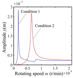
Based on the API Standard 617 [17], two unbalance loading conditions are determined for the rotor system. The material parameters, bearing parameters and loads which are used to simulate the looseness fault are shown in Table 1. The modal damping ratios are assumed as 0.04 and the geometric parameters of the rotor system can be found in Ref. [18]. Without regard to pedestal looseness, the unbalance responses of disc 2 (node 19) at vertical direction (y direction) under two loading conditions are shown in Fig. 4. It can be observed from the figure that the first order resonant response is predominant at 1680 r/min under the first loading condition and the second order resonant response at 6450 r/min under the second loading condition.
Table 1Parameters of the rotor, bearing and pedestal
Material parameters | Elastic modulus E (GPa) | Poisson’s ratio | Density (kg/m3) | |
207 | 0.3 | 7850 | ||
Bearing parameters | Horizontal stiffness (MN/m) | Vertical stiffness (MN/m) | Horizontal damping (kN·s/m) | Vertical damping (kN·s/m) |
200 | 500 | 2 | 2 | |
Pedestal parameters | Base stiffness (MN/m) | Base damping (kN·s/m) | Pedestal mass (kg) | |
200 | 0.2 | 1.256 | ||
First unbalance loading condition | Unbalance moment of disc 1 mr (g·m) | Phase angle of unbalance at disc 1 (°) | Unbalance moment of disc 2 mr (g·m) | Phase angle of unbalance at disc 2 (°) |
0.156 | 0 | 0.156 | 0 | |
Second unbalance loading condition | Unbalance moment of disc 1 mr (g·m) | Phase angle of unbalance at disc 1 (°) | Unbalance moment of disc 2 mr (g·m) | Phase angle of unbalance at disc 2 (°) |
0.156 | 0 | 0.156 | 180 |
Fig. 4Unbalance response of the rotor system in y direction under two loading conditions
3.1. Dynamic characteristics under the first loading condition
Under the first loading condition, the influences of the stiffness of non-loosened bolts (), looseness clearance () and rotating speed () on the nonlinear dynamic characteristics of the right journal are analyzed. Only vibration responses of the right journal at looseness position (node 26) are presented in this paper. Since the vibration of the rotor system is violent under the resonance conditions, the influences of and are analyzed under the resonance speed of 1680 r/min and the influences of are discussed finally.
3.1.1. The influence of the stiffness of non-loosened bolts
Assuming the pedestal displacement is less than looseness clearance at = 1680 r/min, namely changes only when the pedestal contacts the base, and the damping of non-loosened bolts changes with different , as is shown in Table 2.
Table 2Stiffness and damping coefficients of non-loosened bolts
/ (N/m) | log ( / 2) | / (N·s/m) |
2×10⁸ | 8 | 2000 |
2×10⁷ | 7 | 1000 |
2×10⁶ | 6 | 500 |
2×10⁵ | 5 | 250 |
2×10⁴ | 4 | 125 |
2×10³ | 3 | 62.5 |
2×10² | 2 | 31.25 |
2×101 | 1 | 15.63 |
2 | 0 | 7.81 |
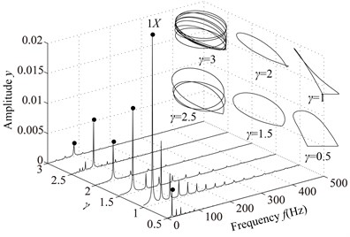
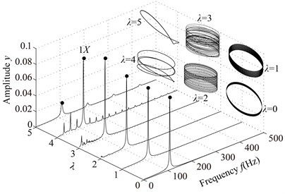
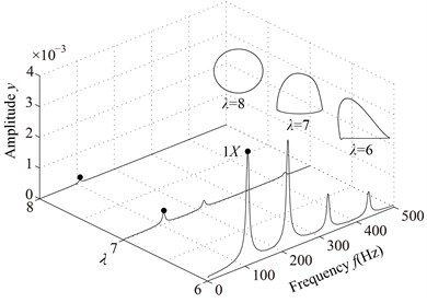
The spectrum cascades and rotor orbits of the system are shown in Fig. 5 based on the parameters in Table 2. In the spectrum cascade, left-hand abscissa is the pedestal equivalent stiffness () and 1 denotes the rotating frequency. The rotor orbits under different are shown in the right side. From Fig. 5, it is clear that the amplitude of the right journal increases with the decrease of . The spectral components display only 1 at 8, integer-order super-harmonics 1, 2, 3, … at 7, 6, 5, 4; 1/2 fractional harmonic components, such as 1/2, 3/2, etc., at 3; complicated lower frequency components at 2; and only 1 at 1, 0. The rotor orbit shows a circle at 8; an ellipse with limited bottom at 7, 6, 5, 4; two ellipses at 3, which shows the system motion is P2 (period-2); an upward spiral at 2, 1 and a translational ellipse along pedestal looseness direction at 0 because the pedestal motion breaks away from the base. The system motion is also determined by Poincaré maps, as is shown in Fig. 6. From the figure, it can be seen that P2 motion appears at 3 and chaotic motion at 2.
Fig. 5Vibration responses of the rotor system at different λ under condition 1
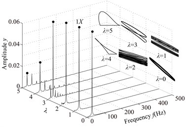
a)0, 1, 2, 3, 4, 5
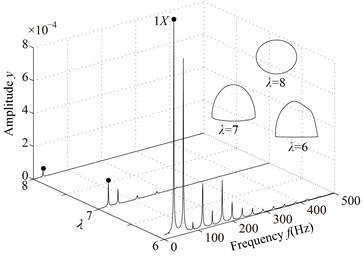
b) 6, 7, 8
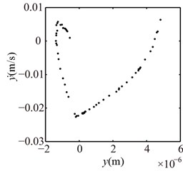
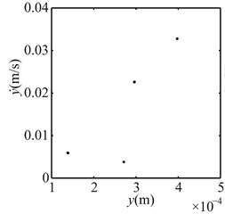
Fig. 6Poincaré maps at λ= 4, 3, 2 under condition 1
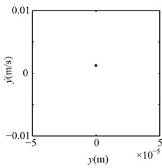
a) 4
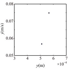
b) 3
c) 2
3.1.2. The influence of the looseness clearance
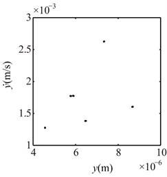
Assuming 1680 r/min and 1 mm, will change twice only when . The loosened bolts under this condition, which is similar to double constraint problem.In this paper, starts from 3, and occurs at 3, 2, 1, 0. The vibration responses of the right journal are shown in Fig. 7 and Poincaré maps at 3, 2, 1 in Fig. 8. It can be seen from the spectrum cascade (see Fig. 7) that 1/3 fractional harmonic components, such as 1/3, 2/3, 4/3, etc. and some continous spectra in the high frequency range appear at 3; the low combination frequency components besides high combination frequency components and contious spectra at 2, 1, 0. The rotor orbit shows the limits of the bottom and the top. Poincaré maps (see Fig. 8) show that choatic motions appear at 3, 2, 1. The appearances show that the contact and rebound times of the pedestal between the base and the loosened bolts increase with the decrease of .
Fig. 7Vibration responses of rotor system at λ= 3, 2, 1, 0 under condition 1
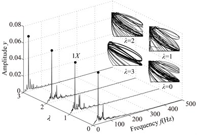
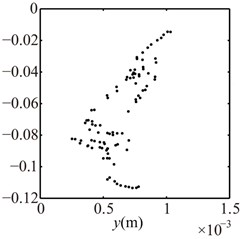
Fig. 8Poincaré maps at λ= 3, 2, 1 under condition 1
a) 3
b) 2
c) 1
3.1.3. The influence of rotating speeds
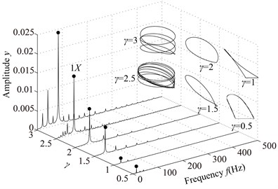
The stiffness and damping of non-loosened bolts are assumed as 20 kN/m and 125 N·s/m, respectively. Assuming , namely changes when the pedestal contacts the base. The rotating speed parameters are listed in Table 3. The vibration responses of the rotor system with pedestal looseness under different are shown in Fig. 9 and Poincaré maps at 3, 3.5, 4, 4.5, 5, 6 in Fig. 10.
In the spectrum cascade, left-hand abscissa is the ratio of the rotating speed to the first critical speed (). From the figure it can be seen that the system response shows several integer-order super-harmonics ( 1, 2, 3, …) at 0.5, 1, 1.5, 2. fractional harmonic components can be observed at 3, 4, 5, 6, which shows that the system motions are period-. Poincaré map at 3.5 shows that the chaotic motion appears; P10 at 4.5, which is also proved by 1/10 with small amplitude in spectrum cascade; P6 at 5.5. From the rotor orbits, it is obvious that the right journal vibrates violently and its orbit is similar to a spiral spring along looseness direction at high rotating speeds.
Table 3Rotating speed parameters
Rotating speed / (r/min) | Rotating speed (r/min) | ||
840 | 0.5 | 5880 | 3.5 |
1680 | 1.0 | 6720 | 4.0 |
2520 | 1.5 | 7560 | 4.5 |
3360 | 2.0 | 8400 | 5.0 |
4200 | 2.5 | 9240 | 5.5 |
5040 | 3.0 | 10080 | 6.0 |
Fig. 9Vibration responses of the rotor system at different γ under condition 1
a) 0, 0.5, 1, 1.5, 2, 2.5, 3
b) 3.5, 4, 4.5, 5, 5.5, 6
Fig. 10Poincaré maps at γ= 3, 3.5, 4, 4.5, 5, 6 under condition 1
a) 3
b) 3.5
c) 4
d) 4.5
e) 5
f) 6
3.2. Dynamic characteristics under the second loading condition
Under the second loading condition, the parameters of the rotor, bearing and pedestal are the same as those under the first loading condition and the rotating speed 6450 r/min is selected to analyze the influences of and on the vibration responses of the right journal.
3.2.1. The influence of the stiffness of non-loosened bolts
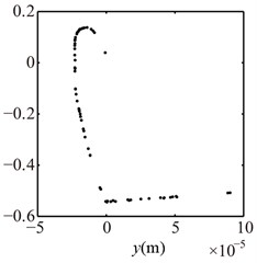
The system vibration responses at different are shown in Fig. 11 and Poincaré maps at 4, 3, 2 in Fig. 12. It can be seen from Figs. 11 and 12 that the system motion is P1 at 8, 7, 6, 5 and rich multiple frequency components appear with the decrease of ; P4 appears at 4, chaotic motion at 3, 2 and P1 at 1, 0. The rotor orbits are stable at 8, 7, 6, 5, fluctuate along looseness direction at 4, 3, 2, 1. An ellipse orbit at 0 indicates that the non-loosened bolts lose their binding force for the pedestal and the pedestal is suspended, which shows that there is no contact between the pedestal and the base by analyzing the position of the right pedestal in y direction.
Fig. 11Vibration responses of the rotor system at different λ under condition 2
a) 0, 1, 2, 3, 4, 5
b) 6, 7, 8
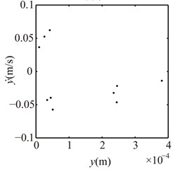
Fig. 12Poincaré maps at λ= 4, 3, 2 under condition 2
a) 4
b) 3
c) 2
3.2.2. The influence of the looseness clearance
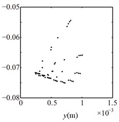
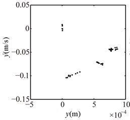
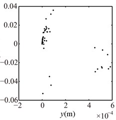
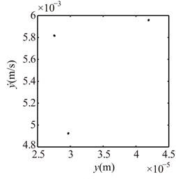
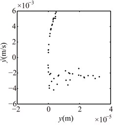
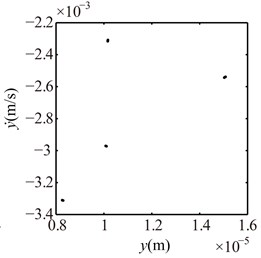
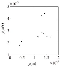
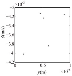
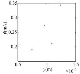
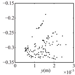
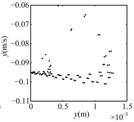
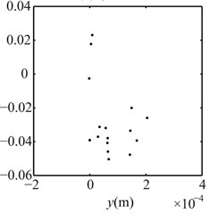
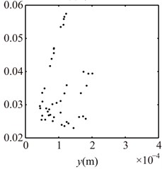
The vibration responses of the right journal under and 1 mm are shown in Fig. 13 and Poincaré maps at 3, 2, 1 in Fig. 14. Multiple frequency components, such as 2, 3, etc., and some combination freqeuncies with small amplitude appears and rotor orbits are limited at the bottom and the top at 4, 3, 2, 1, 0. The Poincaré maps are similar at 3, 2, 1, which shows that the system motions are quasi-periodic. These features are different than these under condition 1 (see Figs. 7 and 8).
3.2.3. The influence of rotating speeds
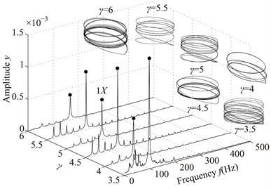
The parameters are the same as those under the condition 1, and the vibration responses of the rotor system at different are shown in Fig. 15 and Poincaré maps at 3, 3.5, 4, 4.5, 5, 6 in Fig. 16. It can be seen from the Figs. 15 and 16 that the integer-order super-harmonics ( 1, 2, 3, …) at 0.5, 1, 1.5, 2. P8 appears at 2.5; P4 at 3, 4; chaotic motion at 3.5, 6; P10 at 4.5; P16 at 5; and P6 at 5.5. The rotor orbits are similar to upward spirals at large , which are similar to those under condition 1.
The system motion forms under two loading conditions are listed in Table 4.
Fig. 13Vibration responses of rotor system at λ= 4, 3, 2, 1, 0 under condition 2
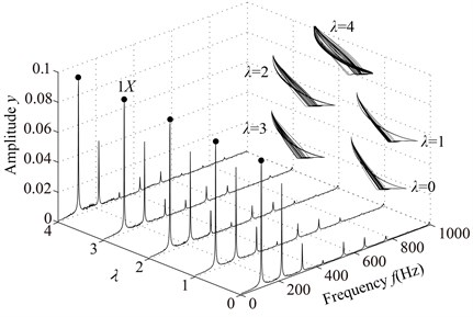
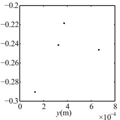
Fig. 14Poincaré maps at λ= 3, 2, 1 under condition 2
a) 3
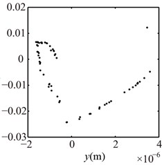
b) 2
c) 1
Fig. 15Vibration responses of the rotor system at different γ under condition 2
a) 0, 0.5, 1, 1.5, 2, 2.5, 3
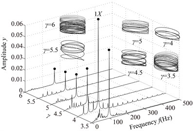
b) 3.5, 4, 4.5, 5, 5.5, 6, 6.5
Fig. 16Poincaré maps at γ= 3, 3.5, 4, 4.5, 5, 6 under condition 2
a) 3
b) 3.5
c) 4
d) 4.5
e) 5
f) 6
Table 4Comparison of system motion forms under two loading conditions
Parameters of influence | Condition 1 | Condition 2 | ||||
Values | System motion | Frequency features | Values | System motion | Frequency features | |
log (/ 2) under | 8, 7, 6, 5, 4 | P1 | 1X, 2X, 3X, etc. | 8, 7, 6, 5 | P1 | 1X, 2X, 3X, etc. |
3 | P2 | 1X/2, 1X, 3X/2, etc. | 4 | P4 | 1X/4, 1X/2, 3X/4, etc. | |
2 | Chaotic motion | Continuous spectra | 3, 2 | Chaotic motion | Continuous spectra | |
1, 0 | P1 | 1X | 1, 0 | P1 | 1X | |
log (/ 2) under | = 3, 2, 1, 0 | Chaotic motion | Continuous spectra | 4, 3, 2, 1, 0 | Quasi- periodic | 1X, 2X, 3X and some combination frequency components |
/ | = 0.5, 1, 1.5, 2 | P1 | 1X, 2X, 3X, etc. | = 0.5, 1, 1.5, 2 | P1 | 1X, 2X, 3X, etc. |
= 3, 4, 5, 6 | Period- | 1X/, 2X/, etc. | = 2.5 | P8 | 1X/8, 1X/4, 3X/8, etc. | |
= 3.5 | Chaotic motion | Continuous spectra | = 3 | P4 | 1X/4, 1X/2, 3X/4, etc. | |
= 4.5 | P10 | 1X/10, 1X/5, 3X/10, etc. | = 3.5, 6 | Chaotic motion | Continuous spectra | |
= 5.5 | P6 | 1X/6, 1X/3, 1X/2, etc. | = 4.5 | P10 | 1X/10, 1X/5, 3X/10, etc. | |
= 5 | P16 | 1X/16, 1X/8, 3X/16, etc. | ||||
= 5.5 | P6 | 1X/6, 1X/3, 1X/2, etc. | ||||
4. Conclusions
In this paper, nonlinear dynamic characteristics of a rotor system with pedestal looseness fault are simulated under two loading conditions by considering the effects of the stiffness of non-loosened bolts, looseness clearance and rotating speeds. The following conclusions can be drawn from the present study:
(1) When the pedestal displacement is less than the looseness clearance, with the decrease of the stiffness of non-loosened bolts, the system motion under the first loading condition changes from P1 through P2, chaotic motion to P1. However, the system motion under the second loading condition changes from P1 through P4, chotic motion to P1.
(2) When the pedestal displacement is greater than the looseness clearance, with the decreases of the stiffness of non-loosened bolts, chaotic motion appears under the first loading condition, but quasi-periodic motion under the second loading condition.
(3) When the pedestal displacement is less than the looseness clearance, the system motion is P1 under the rotating speed less than or equal to two times of the first critical speed. Periodic motion and chaotic motion appear alternately when the rotating speed is greater than two times of the first critical speed. And periodic motion forms under condition 2 are more complicated than those under condition 1.
References
-
Wen B. C., Wu X. H., Ding Q., et al. Theory and Experiment of Nonlinear Dynamics for Rotating Machinery with Faults. Science, 2004.
-
Muszynska A., Goldman P. Chaotic responses of unbalanced rotor bearing stator systems with looseness or rubs. Chaos, Solitons and Fractals, Vol. 5, Issue 9, 2009, p. 1683-1704.
-
Muszynska A. Rotordynamics. Boca Raton, CRC, 2005.
-
Chu F., Tang Y. Stability and non-linear responses of a rotor-bearing system with pedestal looseness. Journal of Sound and Vibration, Vol. 241, Issue 5, 2001, p. 879-893.
-
Lu W., Chu F. Experimental investigation of pedestal looseness in a rotor-bearing system. Key Engineering Materials, Vols. 413-414, 2009, p. 599-605.
-
Duan J. A., Huang Z. K. Nonlinear model of rotor system with loose fault. Journal of Central South University of Technology, Vol. 33, Issue 1, 2002, p. 78-81.
-
Chen G. Nonlinear dynamics of unbalance-looseness coupling faults of rotor-ball bearing-stator coupling system. Chinese Journal of Mechanical Engineering, Vol. 44, Issue 3, 2008, p. 82-88.
-
Kim Y. B., Choi S. K. A multiple harmonic balance method for the internal resonant vibration of a non-linear Jeffcott rotor. Journal of Sound and Vibration, Vol. 208, Issue 5, 1997, p. 745-761.
-
Hossain M. Z., Mizutani K., Sawai H., et al. Preloading effects on clearance problem in rotor-coupling vibration system: experimentation and simulation. Chaos, Solitons and Fractals, Vol. 14, Issue 9, 2002, p. 1371-1378.
-
Gonsalves D. H., Neilson R. D., Barr A. D. S. A study of the response of a discontinuously nonlinear rotor system. Nonlinear Dynamics, Vol. 7, Issue 4, 1995, p. 451-470.
-
Karpenko E. V., Wiercigroch M., Cartmell M. P. Regular and chaotic dynamics of a discontinuously nonlinear rotor system. Chaos, Solitons and Fractals, Vol. 13, Issue 6, 2002, p. 1231-1242.
-
Karlberg M., Aidanpaa J. O. Investigation of an unbalanced rotor system with bearing clearance and stabilizing rods. Chaos, Solitons and Fractals, Vol. 20, Issue 2, 2004, p. 363-374.
-
Gao S. H., Long X. H., Meng G. Nonlinear response and nonsmooth bifurcations of an unbalanced machine-tool spindle-bearing system. Nonlinear Dynamics, Vol. 54, Issue 4, 2008, p. 365-377.
-
Ren Z. H., Chen H., Ma H., et al. Pedestal looseness fault analysis of a vertical dual-disk over-hung rotor-bearing system. Transactions of the Chinese Society for Agricultural Machinery, Vol. 38, Issue 11, 2007, p. 196-201.
-
Ma H., Zhao X. Y., Teng Y. N., et al. Analysis of dynamic characteristics for a rotor system with pedestal looseness. Shock and Vibration, Vol. 18, Issues 1-2, 2011, p. 13-27.
-
Behzad M., Asayeshthe M. Numerical and experimental investigation on vibration of rotors with loose discs. Proceedings of the Institution of Mechanical Engineers, Part C: Journal of Mechanical Engineering Science, Vol. 224, Issue 1, 2010, p. 85-94.
-
API 617 Axial and Centrifugal Compressors and Turboexpanders for Petroleum. Chemical and Gas Industry Services, American Petroleum Institute, Washington D. C., 2002.
-
Ma H., Tai X. Y., Sun J., et al. Analysis of dynamic characteristics for a dual-disk rotor system with single rub-impact. Advanced Science Letters, Vol. 4, Issues 8-10, 2011, p. 2782-2789.
About this article

We are grateful to the China Natural Science Funds (NSFC, Grant No. 50805019), the Fundamental Research Funds for the Central Universities (Grant No. N100403008) and Program for New Century Excellent Talents in University (Grant No. NCET-11-0078) for providing financial support for this work.
