Abstract
With the ability to provide close surveillance in narrow space or urban areas, unmanned aerial vehicles (UAVs) have been of great interest to many scholars and researchers. The spherical aerial vehicle offers substantial design advantages over the conventional small aerial vehicles. As a new kind of small aerial vehicles, spherical aerial vehicle is presented in this paper. Firstly, the unique structure of spherical aerial vehicle is presented in detail. And then the dynamics theory based on this vehicle’s structure is analyzed, and the equations of force and moment acting on the aircraft were deduced. Based on the above, the dynamics model of spherical aerial vehicle is derived and the nonlinear state equation is established. The control system of the spherical aerial vehicle’s flight motion, including the hardware and software parts, is presented concretely. The backstepping control method is used in the state equation to get the stability of the spherical aerial vehicle’s motion. At last, the experimental results and simulation analysis are provided to confirm the feasibility of the spherical aerial vehicle’s flight movement in the air.
1. Introduction
UAV (Unmanned aerial vehicle) is one of the hottest research fields in robotics because of its low cost, operational environment, and small size. It is a kind of person-portable aircraft which has flexible movement in the relatively small areas. With the ability to provide close surveillance in narrow space or urban areas, UAVs have been of great interest to many scholars and researchers [1-3]. With the rapid development of UAV technology [4], the UAV can move in an increasing number of different environments to realize many functions, such as environmental monitor, aerial mapping and traffic monitor. So it will last a long time for developing the UAV technology, and the UAV will play an important and irreplaceable role in the development of aircrafts. Nowadays, UAV is classified into two categories: fixed-wing UAV and VTOL (Vertical take-off and landing) UAV. Fixed-wing UAV has been researched and developed for many years. These UAVs can fly in the air with higher speed and less power. Their mature structure design and control system has made it a popular choice in the field of aircrafts. But these UAVs require a long and flat runway to take off and land, and their turning radius is relatively larger, so their movement is not flexible. Specially, the VTOL aircrafts have got more interest than the fixed-wing UAV because VTOL UAV can take off in a small area instead a runway and can hover in the air, and their turning radius is zero, so it can fly in the air freely.
Cypher I and Cypher II [5, 6] are series of VTOL UAV developed by Sikorsky Aircraft Corporation. They have two opposing rotors in a circular shroud for propulsion and can realize vertical takeoff and landing. They have two propellers of the opposing rotation to offset the torque, and this design of the aircraft reduces the difficulty and complexity of the control system. Honeywell RQ-16 T-Hawk [7], a “scout” which can stop in the building to monitor targets, is developed by the department of defense and aerospace electronic system in Honeywell International, Inc. The MAV's key point is that the micro-electro-mechanical systems technology (MEMS) is applied in its autonomous flight control system (FCS), so the flight control system has the advantages of miniaturized system, fast response and low cost. It is a kind of aircraft which can be carried by person. ISTAR [8] is a ducted aircraft developed by the United Aerospace, and the aircraft can execute the tasks of intelligence, surveillance, reconnaissance and identification. Quadcopters, which have four rotors to realize the free flight in air, are popular in the UAV’s research and study in many universities and institutes [9, 10]. They can create many functions as other aircrafts, and are easy to control and stabilize. Quadcopters can cancel angular momentum by employing two clockwise spinning rotors and two counter clockwise rotors [11]. The typical example is a quadcopter named Parrot AR. Drone developed by the French company Parrot [12], and it can be easily controlled by the smartphones, such as the iphones and the android phones.
In this paper, spherical aerial vehicle, a new kind of VTOL UAV with unique structure, is introduced and presented. As a new king of unmanned aerial vehicle, spherical aerial vehicle has been started to develop recently [13]. In Japan, a researcher, named Fumiyuki Sato, developed flying sphere drone at Defence Ministry’s Technical Research and Development Institute in 2011. This flying sphere drone is 350 grams weight, and the diameter is 41 cm. This machine can realize flying in the air by controlling the propeller’s rotation speed and the angle of control flaps.
Professor Sun, Hanxu in Beijing University of Posts and Telecommunications have started to research spherical mobile robot since 2000 [14-17], and developed many kinds of spherical mobile robots, such as spherical robots based on relocation of mass point, a spherical robot with manipulator, spherical robot of hemispheric differential motion and spherical underwater vehicle. Spherical aerial vehicle is developed based on the spherical mobile robots in Beijing University of Posts and Telecommunications, and it combines the characters of spherical mobile robot and VTOL UAV, so the spherical aerial vehicle can fly in the air freely and move on the ground effectively. Its meshed hollow spherical shell protects the propeller, motors, all control circuits, power supply devices, and inner frame enclosed in spherical shell. Due to the characteristics of its shape, spherical aerial vehicle can land on the ground in arbitrary posture from the flight, and even if the spherical aerial vehicle is out of control, the shell can also effectively protect inner part of the vehicle.
This paper is organized as follows. Firstly, the unique structure and features of spherical aerial vehicle are introduced in detail. The structures of spherical aerial vehicle’s flight motion and moving movement are respectively presented concretely. Secondly, the dynamics theory based on this vehicle’s structure is analyzed, and the equations of force and moment acting on the spherical aerial vehicle were deduced. Due to the above analysis, the dynamics model based on the unique structure features of spherical aerial vehicle is established. Thirdly, the control system for vehicle’s flight motion is stated, including the hardware and software. Fourthly, the backstepping control method is used in the hovering motion to stabilize the spherical aerial vehicle’s movement. At last, the simulations and experimental results are provided to confirm the feasibility of the spherical aerial vehicle’s dynamics theory and control method.
2. Spherical aerial vehicle’s structure
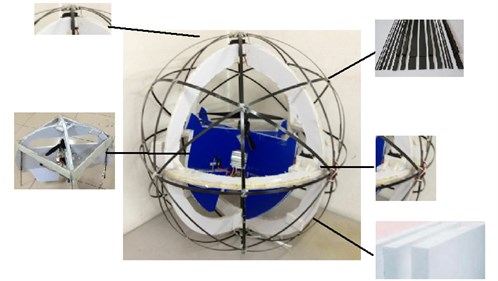
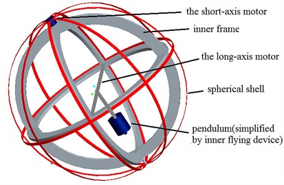
The spherical aerial vehicle developed in our lab is shown in Fig. 1 and Fig. 2. The spherical aerial vehicle can complete the six degrees of freedom of movement for spherical aircraft in the air and move flexibly on the ground. It has a unique structure and is composed of five parts: long-axis motor, short-axis motor, spherical shell, inner flying device and inner frame.
As illustrated in Fig. 2, the top left part is the short-axis motor, which makes relative rotation of the spherical shell and the inner frame around the short axis to realize changing the direction of rolling movement on the ground and swinging flight in the air; the bottom left part is the inner flying device, which can realize the flight function for the vehicle, and the control rudders are set at the bottom of this part; the top right part is the meshed spherical shell made from the carbon fiber, and this meshed spherical shell can make the vehicle roll with a full range of attitude on the ground; the middle right part is the long-axis motor, which makes the inner flying device rotate around the long axis as a pendulum to make the vehicle move forward on the ground or make the aerial vehicle fly forward in the fight motion; the bottom right part is the inner frame, which is a frame to connect the spherical shell to the inner flying device with the long-axis and short-axis motors.
Fig. 1Schematic of spherical aerial vehicle’s structure
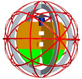
Fig. 2Prototype of spherical aerial vehicle
The inner flying device, which realizes the flight motion of the spherical aerial vehicle, is the main part of the aerial vehicle. The propeller and the brushless motor are fixed to the top of the bracket framework, and by them to provide the lift of the entire robot. The bottom of the brushless DC motor’s stator is fixed on the center axis of the cross bracket, and this will ensure that the air stream of propeller’s rotation flows along the axis symmetrically. High-speed rotation of the brushless motor makes propeller generate a downward airflow, and the entire robot will be acted on an upward lift. So when the upward lift generated by the propeller is greater than the gravity of the robot itself, the spherical aerial vehicle will take off from the ground vertically with acceleration. The components of the inner flying device are shown in Fig. 3.
As a support strut, the bracket framework is designed to support the brushless motor and propeller, and the electronic speed controller, battery, the long axis motor and other devices components are placed in it. At the same time, the bracket framework (as shown in Fig. 4) is designed in the cross-shape, because this design can effectively remove the swirl from the airflow generated by propeller’s high-speed rotation and make the air stream flow along the axis of the propeller as much as possible. The swirl flow, which represents a form of energy loss, is part of the energy of the air stream in disorder rather than to generate thrust in the axial direction. And this design of the bracket framework can reduce the transverse momentum component of the vehicle, and only generate torque and axial force.
The control rudders are placed at the bottom of the bracket framework and they are designed to change the directions of the air flow from the propeller’s high speed rotation. This design of control rudders is very simple, and it is similar in design and construction of a typical fixed-wing aircraft’s elevator and rudder. The four control rudders are used to not only offset the torque of the propeller’s high-speed rotation, but also change the direction of the spherical aerial vehicle’s movement. The four control rudders deflect with the different directions to achieve changing the three Euler angles (roll/pitch/yaw) of spherical aerial vehicle, and the vehicle can realize the movement of the six degrees of freedom in the air. The diagram of the moment driven by control rudders is shown in Fig. 5.
Fig. 3Photo of inner flying device 1 – the propeller and the brushless motor; 2 – bracket framework; 3 – control rudders
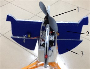
Fig. 4Schematic of bracket framework
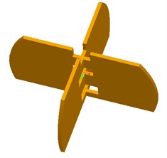
Fig. 5The movement driven by control rudders
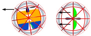
a) roll
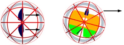
b) pitch
c) yaw
The spherical aerial vehicle is designed to not only fly in the air with six degrees of freedom, but also move on the ground effectively. In our laboratory, the spherical mobile robot relies on a pendulum for propulsion that effectively relocates the center of gravity of the robot to make it move forward on the ground. Based on the principle, spherical aerial vehicle is designed with this mechanism to achieve its movement on the ground.
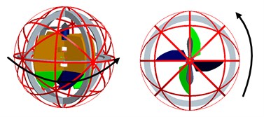
During the process of the spherical aerial vehicle’s structural design, the heavy pendulum as the key part is considered firstly. Because the inner flying device is placed inside the spherical shell, it is very difficult to install the heavy pendulum at the bottom of the inner flying device. In order to reduce the entire weight of the robot, the inner flying device is designed as the vehicle’s pendulum. And at the same time the short-axis motor cannot be fixed in the center of the inner flying device to make the pendulum swing to realize changing the direction of the spherical aerial vehicle’s movement. So the long axis of the frame is designed as the inner frame, and the inner flying device as the pendulum rolls around the long axis to make spherical aerial robot move forward. In order to achieve changing the direction of the spherical aerial vehicle’s movement, the inner frame and the spherical shell rotate around the short axis to change the direction of the pendulum’s movement and realize achieving a turning motion of the spherical aerial robot. The design diagram of the spherical aerial vehicle’s rolling on the ground is shown in Fig. 6.
Fig. 6The design diagram of the spherical aerial vehicle’s rolling on the ground
3. Dynamic analysis and modeling
In the flight mode, the spherical aerial vehicle has the similar body coordinate system with the other VTOL UAV, so we adopt the standard coordinate system in this section. Firstly, we make the definition of various coordinate systems for the description of spherical aerial vehicle’s motion. This aerial vehicle has six degree of freedom in the flight motion. The ground coordinate system is defined as and the vehicle’s coordinate system as, and the Euler angles rotating about the axis ,, of the body are respectively set as (roll angle), (pitch angle), (yaw angle). The coordinate system of the spherical air vehicle is shown in Fig. 7.
Fig. 7Coordinate system of spherical aerial vehicle
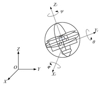
When the spherical aircraft is flying in the steady state in the air, the attitude angle is varied in a small range, so the Euler angles singularity in transformation matrix does not exist. The transformation matrix involving the ground coordinate system and the coordinate system of the body is expressed as:
where , and
From the above formula we can get the relationship between Euler angle rate , , and the rotational angle rate , , in the body coordinate system. The differential equations of aircraft in the matrix form are:
where ;; is the mass of the spherical aerial vehicle; ,,are respectively moments of inertia for the coordinate system; ,, are respectively products of inertia.
The scalar equations consist of six non-linear differential equations of forces and moment as follows:
The forces and moments of the spherical aerial vehicle are presented firstly. The force in the spherical aircraft contains the gravity, the propeller lift, rudder aerodynamic.
All the components of gravity in the body coordinate system can be expressed as follows:
As shown in Fig. 7, the original point of the coordinate system of the body is located in the geometric center of the spherical aerial vehicle, so:
We can use the simplified aerodynamic parameters to calculate the aerodynamic forces and moments of the aircraft. The component of propeller lift and lifting moment in the coordinate system of the body can be expressed:
where is the induced velocity of the rotor surface, is the air density, is the rotor radius, is the area across propeller; is angular velocity of propeller.
The offset of propeller torque and movement control is achieved by four cross rudder. The vehicle’s roll and pitch angle’s change is achieved by its corresponding rudder surfaces around the axis with the same direction, and the yaw angle’s change is realized by the four rudders around axis clockwise or anti-clockwise. Here we ignore the coupling effect of the four rudders, so the rudder’s aerodynamic equation can be got:
where represents rudder area; , and represent rudders’ deflection angle; , and represent the moments of the control rudders. And the rudders’ deflection angle and moment of the rudders can be expressed as follows:
where ,,, are respectively the four rudder’s deflection angles and , , and are respectively the moments of the four control rudders.
According to these three forces, we can get the expression of the total force and moment of the spherical aerial vehicle:
And the model of spherical aerial vehicle can be generally simplified as the expression of nonlinear dynamics of in the form of state equation:
where is state vector, is input vector, is output vector, ,
4. Control system for flight motion
4.1. Hardware
In order to realize the spherical aerial vehicle’s flight motion, a variety of electrical devices are installed in the inner flying device, such as the electrical speed controller, battery, gyroscope, servos and main controller. The spherical aerial vehicle is on the basis of the ARM processor AT91SAM7X256 as the controller core. Power is supplied by a +15 V lithium battery with the capacity of 300 MAh. Brushless DC motor is connected to the battery through the electrical speed controller. The electrical speed controller provides a +5 V stable voltage for the main controller and gyroscope. The control rudders’ deflection angles are driven and controlled by the four servos. The main controller contains serial RS232 communication ports, the I/O (Input/Output) pins and PWM (Pulse Width Modulation) output pins. Through the serial RS232 communication protocol, a gyroscope named MTi, which is a miniature, gyro-enhanced attitude and heading reference system (AHRS), provides drift-free 3D orientation and 3D rate of turn (rate gyro) of the spherical aerial vehicle to the main controller. The main controller’s I/O ports connect the wireless communication receiver module to receive the commands from the remote controller. The main controller sends the PWM signals to the brushless motor’s electrical speed controller and the rudders’ servos through PWM output pins. These devices can realize the spherical aerial vehicle’s flight movement in the air. The diagram of electronic components of spherical aerial vehicle for flight motion is shown in Fig. 8.
4.2. Software
In the main controller board, the software is developed for the overall control of the spherical aerial vehicle. It follows a general procedure that allows it to examine all devices, to complete a self-diagnostic test, to receive the data from the gyroscope, and to give commands to the driven systems of the actuators.
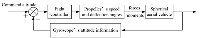
In order to realize the real time control of the spherical aerial vehicle’s flight, the gyroscope sends the real time data of vehicle’s attitude information to the main controller, and the remoter controller sends the commands for flight motion of spherical aerial vehicle. In the main controller, the two sets of data are compared and computed, and the signals for propeller’s speed and control rudders’ deflection angles are got in the flight controller. And then the main controller converts the above results to the motors’ input signals. So the main controller transmits the final results to the brushless motor’s electrical speed controller and the control rudders’ servos directly. Such a cyclic process can achieve a stable control of the spherical aerial vehicle’s attitude. The control diagram of spherical aerial vehicle’s flight motion is shown in Fig. 9.
Fig. 8Hardware of spherical aerial vehicle for flight motion
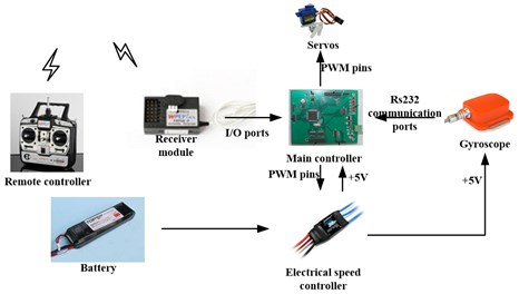
Fig. 9Spherical aerial vehicle’s flight control diagram
5. Control algorithm research
Spherical air vehicle has six degrees of freedom (DOF) in the air, while it can only be driven by the propeller to provide lift, servos to control rudders, long-axis and short-axis motors to control motion direction. So it is obviously an underactuated system. For the above spherical air vehicle’s underactuated features, we design a controller based on backstepping method [18-21].
Backstepping method is a control theory developed by Petar V. Kokotovic in 1990 and widely used for nonlinear dynamical systems. It is a recursive method associated with Lyapunov stability theory. The backstepping method is used to build Lyapunov function to verify the stability of spherical aerial vehicle. From the above section, we get the state equation of spherical aerial vehicle’s dynamic model. Based on nonlinear dynamic model of spherical aerial vehicle, backstepping method is designed as follows.
Step 1. We set and define as the virtual control input for . We need to design the virtual control input to stablize .
So we define Lyapunov function as and the derivative of function is . Then we set and , then and , so , , and the equilibrium is proven to be stable.
Step 2. From , we get:
Then we define Lyapunov function as and the derivative of function is:
Let , then the control input is:
so we get , and the nonlinear model is proven to be stable.
Based on Lyapunov stability, the control input the dynamics system of spherical aerial vehicle is proven to be stable.
6. Experiment analysis
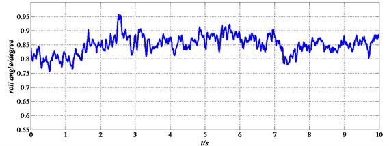
In this section, the experimental results of the spherical aerial vehicle are presented. The prototype of the spherical aerial vehicle is developed in our lab and we have made many experiments to confirm the feasibility of the aerial vehicle. As shown in Fig. 10, the spherical aerial vehicle can fly in the air steadily by the remote controller. And we record the results of the flight experiments in the vertical flight motion. Fig. 11 shows the roll angle of the spherical aerial vehicle’s flight in the air.
Fig. 10Spherical aerial vehicle in flight motion
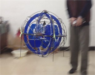
Fig. 11Roll angle of the spherical aerial vehicle’s flight
The performance of hovering state based on the backstepping controller is simulated for spherical aerial vehicle. Computer simulations have been carried out using MATLAB and SIMULINK toolboxes. In order to get the obvious results, we make the experiments with backstepping controller compared with the simple PID controller.
First of all, the state equation of spherical aerial vehicle system is established. Then a control system based on backstepping method is designed, which is different from the control system of PID. After that, Eq. (19) in above section is adopted as the control input. At last, the height of hovering state is set as 2 m. The simulation results are shown in Fig. 12 and Fig. 13. Fig. 12 shows the heights of spherical aerial vehicle in hovering state with the two control methods. Fig. 13 shows the rudder’s angle of spherical aerial vehicle in hovering state with the two control methods.
Fig. 12The height control of spherical aerial vehicle in hovering
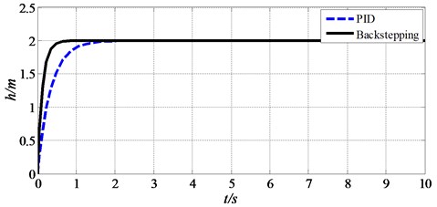
Fig. 13The angle of rudder controlled by servos in hovering
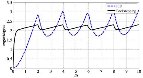
From Fig. 12, we can get that the backstepping control makes the vehicle reach the certain height in 0.7 s and the PID control needs about 2 s to get to 2 m. From Fig. 13, the result shows that the backstepping control reaches the relatively stable state faster than PID control and the amplitude of rudder’s angle change by servos based on backstepping control is smaller than PID control. This makes the spherical aerial vehicle’s hovering movement tends to be smoother with backstepping control. So the simulation results show that the settling time, rising time and amplitudes of response system are significantly improved with backstepping controller in the linear dynamics model of spherical aerial vehicle.
7. Conclusions
In this paper, a novel spherical aerial vehicle is presented. The spherical aerial vehicle is a kind of small aerial vehicle which achieves not only flying in the air with six degrees of freedom, but also moving effectively on the ground. First, to complete the six degrees of freedom of movement for spherical aircraft in the air and on the ground, the spherical aerial vehicle’s structure is designed; then, based on the theories of rigid body dynamics and aerodynamics, the dynamics of the spherical aircraft are analyzed, and the equations of force and moment acting on the aircraft were deduced and its dynamic model is established. In order to realize the effective control of the spherical aerial vehicle, the control system including the hardware and software is stated. To get the stability of the spherical aerial vehicle, the backstepping method is applied in the vehicle’s control. Experiment result shows that the aerodynamic model is of available performance, to facilitate the movement of spherical aerial vehicle in the air.
References
-
Johnson A. N., Turbe M. A. Modeling, control, and flight testing of a small ducted fan aircraft. Journal of Guidance Control and Dynamics, Vol. 29, Issue 4, 2006, p. 769-779.
-
Kendoul F. Modeling and control of a small autonomous aircraft having two tilting rotors. Robotics, IEEE Transactions, Vol. 22, Issue 6, 2006, p. 1297-1302.
-
Kim J. Y., Kang M. S., Sangdeok P. Accurate modeling and robust hovering control for a quad-rotor VTOL aircraft. Journal of Intelligent & Robotic Systems, Vol. 57, Issue 1, 2010, p. 9-26.
-
Guerrero I., Londenberg K. A powered lift aero-dynamic analysis for the design of ducted fan UAVs. Proceedings of 2nd AIAA UAV Conference, San Diego, USA, 2003, p. 1-8.
-
Murphy D. W. Air-Mobile Ground Surveillance and Security System. Project Summary Report, Defense Special Weapons Agency and the Physical Security Equipment Management Office of the Army Aviation and Troop Command, 1996.
-
Murphy D., Cycon J. Application for mini VTOL UAV for law enforcement. Space and Naval Warfare Systems Center, San Diego, CA, 1998.
-
Leishman J. G. Principles of Helicopter Aerodynamics. Cambridge University Press, 40 West 20th Street, New York, USA, 2000.
-
Lipera L., Colbourne J. D., Tischler M. B. The micro craft iSTAR micro air vehicle: control system design and testing. Annual Forum Proc., American Helicopter Society, Inc., Vol. 57, Issue 2, 2001, p. 1998-2008.
-
Achtelik M., Zhang T., Kuhulenz K. Visual tracking and control of a quadcopter using a stereo camera system and inertial sensors. Proc. IEEE International Conference on Mechatronics and Automation, 2009, p. 2863-2869.
-
Bemporad A., Pascucci C. A., Rocchi C. Hierarchical and hybrid model predictive control of quadcopter air vehicles. Analysis and Design of Hybrid Systems, Vol. 3, Issue 1, 2009, p. 14-19.
-
Ohanian O. J. Ducted Fan Aerodynamics and Modeling, with Applications of Steady and Synthetic Jet Flow Control. Doctoral Dissertation, Virginia Polytechnic Institute and State University, 2011.
-
Bristeau P. J., Callou F., Vissiere D. The navigation and control technology inside the AR. Drone Micro UAV, World Congress, Vol. 18, Issue 1, 2011, p. 1477-1484.
-
http://phys.org/news/2011-08-japanese-inventor-sphere-drone.html.
-
Sun H. X., Xiao A. P., Jia Q. X. Omnidirectional kinematics analysis on bi-driver spherical robot. Journal of Beijing University of Aeronautics and Astronautics, Vol. 31, Issue 7, 2005, p. 735-739.
-
Hou K., Sun H. X., Jia Q. X. An autonomous positioning and navigation system for spherical mobile robot. Procedia Engineering, Vol. 29, 2012, p. 2556-2561.
-
Liu D. L., Sun H. X., Jia Q. X. Nonlinear sliding-mode motion control of a spherical robot. Robot, Vol. 30, Issue 6, 2008, p. 498-502.
-
Hou K., Sun H. X., Jia Q. X. Optimal design and experimental verification of a spherical-wheel composite robot with automatic transformation system. Journal of Vibroengineering, Vol. 14, Issue 3, 2012, p. 1378-1389.
-
Krstic M., Kanellakopoulos I., Kokotovic P. V. Nonlinear and Adaptive Control Design. New York, Wiley, 1995.
-
Freeeman R. A., Kokotovic P. V. Design of ‘softer’ robust nonlinear control laws. Automatica, Vol. 29, Issue 6, 1993, p. 1425-1437.
-
Kokotovic P. V. The joy of feedback: nonlinear and adaptive. IEEE Control Systems Magazine, Vol. 12, Issue 3, 1992, p. 7-17.
-
Kanellakopoulos I., Kokotovic P. V., Morse A. S. Systematic design of adaptive controllers for feedback linearizable system. IEEE Transactions on Automatic Control, Vol. 36, Issue 11, 1991, p. 1241-1250.
About this article

The authors wish to acknowledge the support provided by National Natural Science Foundation of China (51175048), Cultivation Fund of the Key Scientific and Technical Innovation Project, Ministry of Education of China (708011).
