Abstract
This paper studies the active vibration control of a cantilever beam structural system by combining the adaptive input estimation method with the fuzzy robust controller. The unknown inputs can be estimated using the measurement dynamic displacement of a beam structural system. That is to say, the adaptive input estimation method can estimate the dynamic inputs of every step time on-line, while the active component applies the same magnitude inverse force into the feedback control. The simulation results show that the proposed synthesis control system has disturbance compensation capability. It can suppress the vibration in a disturbance structural system more effectively and promote controller performance.
1. Introduction
In structural system reliability assessment, fatigue analysis, and anti-vibration design the most important procedure is to obtain the active force values to the structural system. However, in practical engineering problems there are always difficulties in installing load transducers to measure the active forces to the structural system. The impact caused by the loads is sometimes overwhelming and transient preventing measurements from being easily obtained. Therefore, a reverse technology can be applied to solve the above problems. The inverse estimation method is one kind of reverse technology. This method can be used to immediately estimate the unknown input force by measuring the structural system’s dynamic response. Solving the inverse problem usually produces poor numerical phenomena, for example, a very small input change will cause the great output change. In other words, a minimum measurement error will produce a large input estimation error. In order to solve the above problems, Inoue, (1995) [6] used the least square method based on the wiener filtering theory, the mean square error and the singular value decomposition (SVD) to improve the estimation precision and obtain the optimal estimates. Wang (1994) [17, 18] used the weighted total acceleration method to detect the vibration force acting on a concentrated-massed nonlinear beam. Haung (2001) [5] adopted the conjugate method (CGM) to estimate the force of a one-dimensional mass-spring-damper structure with time-varying system parameters. The estimation results were good and acceptable.
The references mentioned above used the batch form to process the measurement data. This kind of method is time-consuming and is not an on-line unknown input estimation procedure. Tuan et al., (1996, 1998) [15, 16] successfully presented an on-line input estimation method that recursively solved the inverse heat conduction problems (IHCPs) in the unknown heat flux estimation. Ma et al., (1998, 2003) [11, 12] presented an inverse method to estimate excitation forces by analyzing the dynamic responses of a structural system. Lee et al., (2008) [9] utilized the adaptive weighted input estimation method to inversely solve the burst load of a truss structural system. Although the above references used on-line estimation ability, better estimation results must calculate through trial and error in the constant weight input estimation algorithm. In other words, an inadequate weighting factor will cause significant deviation (i.e. poor tracking capability) or a large variance (i.e., enlarge measurement error). Chen et al., (2008) [2, 3, 4] investigated the adaptive input estimation method applied to the inverse estimation of load input in a multi-layer shearing stress structure and identified moving loads on a bridge structural system. The overall input estimation performance was acceptable by identifying the structural system dynamic response. However, the estimator convergence had slower reaction time in the initial transient state when the adaptive weighting function was used in the input estimator. An increase in the process noise variance will influence the estimation precision. With a larger process noise variance assumed, better unknown time-varying input tracking capability can be obtained, but the overall noise reduction effectiveness will be degraded. Therefore, Chen and Lee, (2008) [2, 3, 4] further constructed an intelligent fuzzy weighting estimator that fast-tracked and effectively suppressed noise interference, providing effective and robust estimates for the arbitrary unknown input situation. When the initial process noise variance is assumed in the intelligent fuzzy weighting estimator, the overall noise reduction effectiveness will be degraded. The estimates may be divergent in the high order of severity when an inappropriate initial process noise variance is assumed. In order to solve this problem, an effective estimator is accelerated and weighted by adopting the fuzzy accelerating and weighting factor proposed based on the fuzzy logic inference system. This proposed estimator is applied to estimate the unknown inputs on the structural system (Lee and Chen, 2010) [10]. The results are also compared with the results using other algorithms. The reliability, adaptivity and robustness of this method can therefore be verified.
This key point is how to design a controller problem with stochastic dynamic inputs in the system. An ideal solution is to develop a fuzzy controller based on human decision-making thinking. The fuzzy controller can maintain high control performance in the system with environmental uncertainty interference with a control architecture that is easy to implement in engineering and widely used by many engineers. Some studies (Kori et al. 2008 [7], Ying et al. 2009 [19], Zheng et al. 2009 [20]) proposed a semi-active fuzzy control magnetic flow damper to suppress structural system seismic damping control. Teng et al. (2000) [14] and Park et al. (2005) [13] presented the active fuzzy control theory to control structural vibration by seismic forces. Although this fuzzy controller had a certain degree of interference suppression capability, it was difficult to maintain efficient control capacity in the face of complex changes and different external interference problem sizes. Therefore, better control strategies that introduced a disturbance compensator to obtain robust control performance were needed. The external interference is usually difficult to obtain in the control process and the impact of external force is not considered in most fuzzy controller designs. This study therefore combines the adaptive input estimation method with the fuzzy robust controller applied to active cantilever structural system vibration control. In this method the adaptive input estimation method can estimate the unknown dynamic inputs at every step time on-line, while the active component can apply the same magnitude inverse force into the feedback control. This approach can suppress the disturbance vibration in a structural system more effectively and promote controller performance. Fuzzy controller performance depends on the fuzzy rules and membership function design. Therefore, it is important work to design simple and effective fuzzy rules and membership functions in the fuzzy controller design. This study designed an adaptive fuzzy robust controller that considers changes in the external inputs, changes in external input errors and sampling time. The first proposal is a synthesis technique for combining the recursive input estimation method with the adaptive fuzzy control system with disturbance compensation capability. The proposed method can suppress the system vibration more efficiently; be promoted as an integral seismic design system for bridges, buildings and high technological factory for earthquake or wind force vibration suppression. The presented method is a basic seismic design search and early warning system for the structural design engineer. This algorithm can be combined with the optimal control theory to estimate the dynamic inputs for linear structural systems. In order to popularize the research results, the proposed algorithm can be combined with the distinct control theory for developing a robust controller in future research.
2. Mathematical model
This study utilizes the Kalman filtering technique combined with the adaptive weighting factor recursive least squares method to develop an adaptive input estimation method combined with the fuzzy robust controller. The unknown variable inputs can be inverse estimated on-line by measuring the structural system dynamic displacement data. The adaptive fuzzy control theory is added to obtain the optimal feedback control force. The proposed active control system has the flexibility to produce a dynamic response with the actual interference or input to the system. The simulation results show that the controller quickly and accurately assumes control with the damping vibration suppression effect, effectively improving the structural system reliability. The main purpose of this study is to propose an intelligent synthetic control method for active control of a cantilever beam structural system that does not ignore unknown input disturbances. This method combines the adaptive input estimation method with fuzzy control theory. The adaptive input estimation method is used to estimate the system input interference terms, while the fuzzy control theory is used to calculate the optimum feedback control force. The cantilever beam structural system with the random disturbance active control problem is considered in this study. As shown in Fig. 1 the cantilever beam structural system active control problem is simplified in this model.
Fig. 1A skeleton mathematical diagram of the cantilever beam structural system
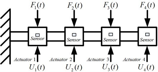
The unknown inputs are applied on a cantilever beam structural system mounted with concentrated masses. The unknown inputs can be estimated using the adaptive input estimation method. The robust fuzzy controller is used to solve the appropriate control forces. The unknown inputs and active control forces are considered in the cantilever beam structural system. The motion equation can be expressed as follows:
where , and are the acceleration, velocity and displacement vectors, respectively. is the mass matrix. is the damping coefficient matrix. is the stiffness matrix. is the input force distribution matrix. is the input force matrix. is the control force distribution matrix. is the control force vector. In order to facilitate input estimation method calculation the state equation and the measurement equation must be constructed before applying this method. In order to satisfy this situation, the equality, , is used to transfer the movement equation to the state space form. The continuous-time state equation and structural system measurement equation can be presented as follows (Tuan et al. 1996) [15]:
where:
the control force is calculated by the fuzzy robust controller.
, and are constant matrices of the structural system. is the state vector. is the input force vector. is the observation vector, and is the measurement matrix.
Noise turbulence always exists in the practical environment. This is the reason that any physical system contains two portions: the first is the deterministic portion, and the second is the random portion, which is distributed around the deterministic portion. Equations (2) and (3) do not take the noise turbulence into account. In order to construct a statistical model of the system state characteristics, a noise disturbance term that reflects these state characteristics will be needed in these two equations. Up to now the Gaussian white noise disturbances can be completely resolved, statistically illustrated in full using the probability distribution function and the probability density function. Any function corresponding to the functions mentioned above has the same effect. The characteristic random variable function is one example. The two most important characteristic values are the mean and the variance, which represent the statistical properties of the random process (Chan, et al. 1979 [1]). Taking the above consideration into account, the continuous-time state equation is sampled using the sampling interval to obtain a discrete-time statistical model of the state equation shown below (Tuan et al. 1996 [15]):
where:
is the state vector. is the state transition matrix. is the input matrix. is the control force distribution matrix. is the sampling interval. is the discrete-time dynamic input force. is the processing error vector, which is assumed as the Gaussian white noise. Note that , and . is the discrete-time processing noise covariance matrix. is the Kronecker delta function. When describing the active characteristics of the structural system, the additional term can be used to present the uncertainty in a numerical manner. The uncertainty could be the random disturbance, the uncertain parameters, or the error due to the over-simplified numerical model.
Generally speaking, the system state can be determined by measuring the system output. This measurement usually has a certain relationship with the system output. However, there is also a noise issue with the measurement. As a result, the discrete-time measurement vector statistical model can be presented below:
is the observation vector. represents the measurement noise vector and is assumed as Gaussian white noise with zero mean and the variance , where . is the discrete-time measurement noise covariance matrix. is the measurement matrix.
3. AIEM combined fuzzy robust controller design
This study presents a synthetic algorithm in which the structure vibration control inputs are not neglected. This algorithm combines the adaptive input estimation method and fuzzy robust controller. The adaptive input estimation method can be used to estimate the unknown system inputs. The fuzzy robust controller uses simple membership functions and fuzzy rules to produce an appropriate feedback control force. The input estimation method is composed of the Kalman filter without the input term and the adaptive least square estimator. The detailed formulation of this method can be found in the research by Tuan et al. 1996 [15].
The Kalman filter without the input term is shown as follows.
The optimal state estimation:
The bias innovation produced by the measurement noise and the input disturbance:
The Kalman gain:
The covariance of the residual:
The prediction error covariance matrix:
The recursive least square algorithm for the input estimation method is shown as follows (Tuan et al. 1996 [15]).
and are the sensitivity matrices:
The correction gain:
The input estimation error covariance:
The vector of the estimated input force:
In Eqs. (15) and (16), is the adaptive weighting factor. The formula is shown as follows (Tuan et al. 1996 [15]):
In the adaptive fuzzy robust controller, by substituting of Eq. (15) for and substituting the control input in Eq. (6), the optimal state estimation equation can be rewritten as:
where the quantity of control force is operated by simple membership functions and fuzzy rules to produce an appropriate feedback control force. The adaptive fuzzy robust controller has a correction weighting factor based on the deviation and deviation rate in each time step. It can be expressed as follows:
where , .
is the estimated inputs, is an expected inputs, is the inputs variation, is the inputs deviation error value and is the correction weighting factor. Equation (18) shows that when the input deviation error value is larger, the control system eliminates , as it needs to have larger . When the input deviation error value is smaller, the main task of the control system is to make sure the system achieves stability as soon as possible to avoid the oscillation phenomenon. The value should be as small as possible at the same time.
The value can be determined by using the fuzzy logic inference system. Its implementation steps are as follows.
Step 1: Define the input and output variables.
From Eq. (18) we must first define and as input variables, as output variable in the fuzzy logic inference system.
Step 2: Determine the linguistic variables fuzzy sets.
The fuzzy sets for input variables and are labeled in linguistic terms, such as NB (Negative Big), NM (Negative Middle), NS (Negative Small), ZE (Zero Value), PS (Positive Small), PM (Positive Middle) and PB (Positive Big). The output variable is labeled in linguistic terms such as PS (Positive Small), PM (Positive Middle) and PB (Positive Big).
Step 3: Determine the fuzzy control rules.
The fuzzy control rules are composed of the input variables and , output variable . A fuzzy rule base is a collection of fuzzy IF-THEN rules as shown in Table 1. The surface viewer of fuzzy rules is shown in Fig. 2.
Step 4: Determine the fuzzy inference method.
The Mamdani maximum-minimum inference engine is used in this study. The output variable max-min-operation fuzzy implication rule is shown as follows (Wang 1994 [17, 18]):
where is the fuzzy rule, and is the input variables dimension.
Step 5: Defuzzifier.
The defuzzifier maps a fuzzy set to a crisp point . The fuzzy logic system with center of gravity is defined as follows (Wang 1994 [17, 18]):
is the number of outputs. is the value of the th output. represents the membership of in the fuzzy set .
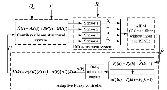
We can obtain an appropriate control force by substituting of Eq. (20) into Eq. (18). We can therefore configure a fuzzy robust controller by combining the adaptive input estimation method with control theory. This controller was applied to the active control of a cantilever beam structural system. A design flow chart of the controller is given in Fig. 3.
Table 1Fuzzy rule base
Output variable | Input variable | |||||||
NB | NM | NS | ZE | PS | PM | PB | ||
Input variable | NB | - | - | - | PM | PB | - | PB |
NM | - | - | - | PM | - | - | - | |
NS | - | - | - | PS | PB | - | PB | |
ZE | PS | PS | PM | PM | PB | PB | PB | |
PS | PS | - | PM | PM | - | - | - | |
PM | - | - | - | PS | - | - | - | |
PB | PS | - | PS | PM | - | - | - | |
Fig. 2The surface viewer of fuzzy rules
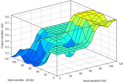
Fig. 3Flowchart of the AIEM combined with the AFC
4. Results and discussion
To verify the effectiveness and robustness of the presented approach in controlling unknown forces, a cantilever beam structural system example was applied to evaluate the present control algorithm. This cantilever beam is divided into 4 elements and 5 nodes, with two degrees of freedom per node, i.e. displacement and rotation and it is mounted with concentrated masses on nodes 1 to 4. As shown in Fig. 1 the cantilever beam mounted with concentrated masses is modeled as a structural system. The element mass matrix and the element stiffness matrix of the cantilever beam are shown as follows (Kwon, 2000 [8]):
where is the mass density. is the cross-section area of the beam. is the length of the beam element. is the elastic modulus of all elements. is the beam cross-section area at the second moment. The concentrated masses . The proportional damping coefficient , where and . The cantilever beam structural system node displacement under various inputs must be determined first. The input forms include the decaying exponential, rectangular and decaying periodic sinusoidal waves, etc. By applying node displacement the inverse input estimation of the structural system can be simulated numerically. The initial conditions and other parameters of the simulation are shown as follows: . is set to be a zero matrix. The sampling intervals , and are adopted in the simulation process. The weighting factor is an adaptive fuzzy weighting function.
4.1. Example 1: decaying exponential inputs estimation and control
This simulation adopts the decaying exponential inputs with different values of amplitude on nodes 1 to 4 of the cantilever beam structural system. The numerical model of the inputs is shown as follows:
The cantilever beam structural system active reaction can be analyzed and applied to the input estimation algorithm using the numerical method when considering the influence due to the processing noise and the measurement noise of the system. The processing noise covariance , where . The measurement noise covariance , where . By applying the active reaction which contains noise to the input estimation algorithm, the time histories of the decaying exponential inputs can be obtained as in Fig. 4. The result reveals very good estimating ability. The estimation values converge to true values quickly. Fig. 5 shows the comparison between the node displacement measurements and estimates of Example 1 with and . The modeling and measurement noises are considered during this case study estimation process. In short, the proposed method has good properties as mentioned above. It can deal with a multiple-input, multiple-output structural system. By applying the active dynamic reaction which contains noise to the presented control algorithm, the time histories of the cantilever beam structural system responses with and without control are shown in Fig. 6.
Fig. 4Estimation results for the decaying exponential input blast loads (Qw=10-4 and Rv=10-14)
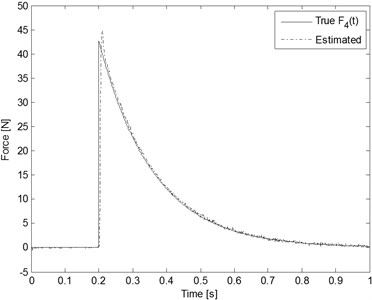
Fig. 5Comparison between the node displacement measurements and estimates when the decaying exponential inputs are applied (Qw=10-4 and Rv=10-14)
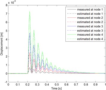
Fig. 6Node displacement comparison with and without control when the decaying exponential inputs are applied

a)
b)
c)
d)
4.2. Example 2: rectangular inputs control
In this case the rectangular inputs acting on nodes 1 to 4 of the cantilever beam FEM model are considered. The numerical model of the input loads is shown as follows:
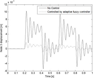
The processing noise covariance , where . The measurement noise covariance where The sampling interval is adopted in this case. Fig. 7 shows the time histories of the rectangular inputs estimation result. The estimation values quickly converge to true values. This result reveals very good estimating ability. The time histories of the responses (node 1 and 3) of a cantilever beam structural system with and without control are shown in Figs. 8 and 9, respectively.
Fig. 7Estimation results for the rectangular inputs
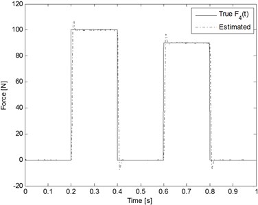
Fig. 8Node 1 displacement comparison with and without control when the rectangular inputs are applied
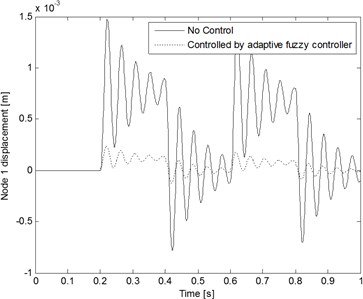
Fig. 9Node 3 displacement comparison with and without control when the rectangular inputs are applied
5. Example 3: decaying periodic sinusoidal wave inputs control
In this case the decaying periodic sinusoidal wave input loads acting on nodes 1 to 4 of the cantilever beam FEM model are considered. The numerical model of the input loads is shown as follows:
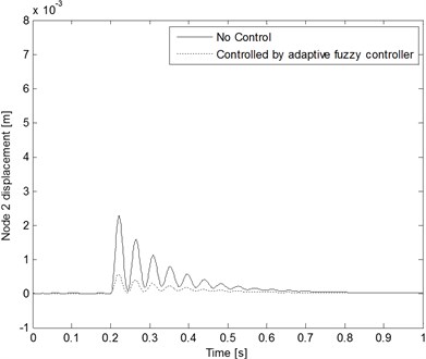
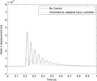
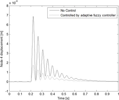
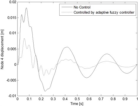
The estimator parameters are the same set as in example 2. Fig. 10 shows the comparison between the true input and the estimates on node 4 of the cantilever beam. The estimation performance is quite acceptable. The time histories of the responses (nodes 2 and 4) of a cantilever beam structural system with and without control are shown in Figs. 11 and 12, respectively. The simulation results for the proposed control method, which combines the adaptive input estimation method and fuzzy robust controller, are suitable for dealing with a time-varying system model control problem.
Fig. 10Estimation results for the decaying periodic sinusoidal wave inputs
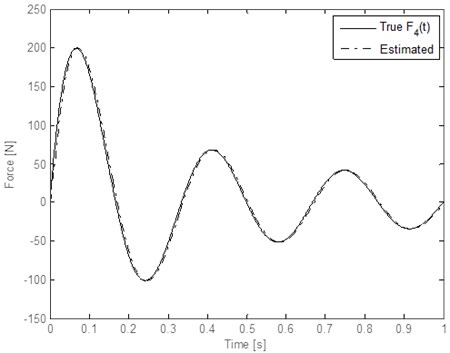
Fig. 11Node 2 displacement comparison with and without control when the decaying periodic sinusoidal wave inputs are applied
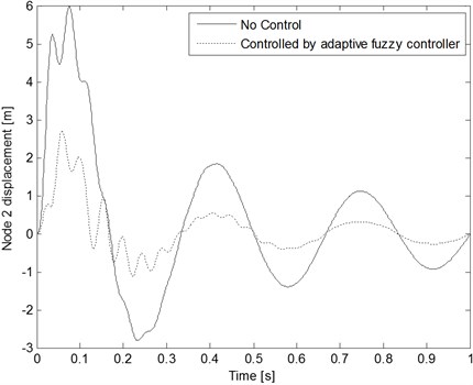
Fig. 12Node 4 displacement comparison with and without control when the decaying periodic sinusoidal wave inputs are applied
The simulation results demonstrate that the proposed controller can be used in active vibration control of a cantilever beam structural system. The unknown input can be estimated using measurement of dynamic displacement of a beam structural system. That is to say the adaptive input estimation method can estimate on-line the dynamic inputs every step time, the active component can apply the same magnitude inverse force into the feedback control. It can suppress the vibration of a disturbance structural system more effectively and promote the control performance of controller. The proposed method can suppress the vibration of a system more efficiently; it can be promoted as integral aseismatic design system of the bridge, building and high technological factory due to the earthquake or wind forces. The presented method is a basic search of the aseismatic design and early warning system for structural design engineer. And further, this algorithm can be combined with the optimal control theory to estimate the dynamic inputs of linear structural system. In order to popularize research results, the proposed algorithm can be combined with the distinct control theory to be promoted in developing a robust controller in the future research.
6. Conclusions
An active control method to suppress cantilever beam structural system vibrations was presented. This control algorithm method is composed of the adaptive input estimation method combined with fuzzy control theory. The proposed method was evaluated using simulation cases with distinct inputs. According to the simulation results, the proposed algorithm combined with fuzzy control theory estimated the dynamic inputs of a linear structural system. Further, it can suppress cantilever beam structural system vibrations more efficiently. This study will address an experimental study for the proposed method in future work.
References
-
Chan Y. T., Hu A. G. C., Plant J. B. A Kalman filter based tracking scheme with input estimation. IEEE Transactions on Aerospace and Electronic Systems, Vol. 15, Issue 2, 1979, p. 237-244.
-
Chen T. C., Lee M. H. Inverse active wind load inputs estimation of the multilayer shearing stress structure. Wind and Structures, An International Journal, Vol. 11, Issue 1, 2008, p. 19-33.
-
Chen T. C., Lee M. H. Research on moving force estimation of the bridge structure using the adaptive input estimation method. Electronic Journal of Structural Engineering, Vol. 8, 2008, p. 20-28.
-
Chen T. C., Lee M. H. Intelligent fuzzy weighted input estimation method applied to inverse heat conduction problems. International Journal of Heat and Mass Transfer, Vol. 51, 2008, p. 4168-4183.
-
Huang C. H. An inverse nonlinear force vibration problem of estimating the external forces in a damped system with time-dependent system parameters. Journal of Sound and Vibration, Vol. 242, 2001, p. 749-765.
-
Inoue H., Ikeda N., Kishimto K., Shibuya T., Koizumi T. Inverse analysis of the magnitude and direction of impact force. JSME Int. J. Series A, Vol. 38, 1995, p. 84-91.
-
Kori J. G., Jangid R. S. Semi-active friction dampers for seismic control of structures. Smart Structures and Systems, An International Journal, Vol. 4, Issue 4, 2008, p. 493-515.
-
Kwon Y. W., Bang H. C. The Finite Element Method Using MATLAB. CRC Press, Boca Raton, 2000.
-
Lee M. H., Chen T. C. Blast load input estimation of the medium girder bridge using inverse method. Defense Science Journal, Vol. 58, 2008, p. 46-56.
-
Lee M. H., Chen T. C. Intelligent fuzzy weighted input estimation method for the input force on the plate structure. Structural Engineering and Mechanics, An International J., Vol. 34, Issue 1, 2010, p. 1-14.
-
Ma C. K., Tuan P. C., Lin D. C., Liu C. S. A study of an inverse method for the estimation of impulsive loads. Int. J. System Sciences, Vol. 29, 1998, p. 663-672.
-
Ma C. K., Chang J. M., Lin D. C. Input forces estimation of beam structures by an inverse method. J. Sound and Vibration, Vol. 259, 2003, p. 387-407.
-
Park K. S., Koh H. M., Ok S. Y., Seo C. W. Fuzzy supervisory control of earthquake-excited cable-stayed bridges. Engineering Structures, Vol. 27, 2005, p. 1086-1100.
-
Teng T. L., Peng C. P., Chuang C. A study on the application of fuzzy theory to structural active control. Comp. Methods Appl. Mech. Engineering, Vol. 189, 2000, p. 439-448.
-
Tuan P. C., Fong L. W., Huang W. T. Analysis of on-line inverse heat conduction problems. Journal of Chung Cheng Institute of Tech., Vol. 25, Issue 1, 1996, p. 59-73.
-
Tuan P. C., Hou W. T. Adaptive robust weighting input estimation method for the 1-D inverse heat conduction problem. Numeral Heat Transfer, Vol. 34, 1998, p. 439-456.
-
Wang M. L., Kreitinger T. J. Identification of force from response data of a nonlinear system. Soil Dynamics and Earthquake Eng., Vol. 13, 1994, p. 267-280.
-
Wang L. X. Adaptive Fuzzy Systems and Control: Design and Stability Analysis. Prentice-Hall, Englewood Cliffs, NJ, 1994.
-
Ying Z. G., Ni Y. Q., Ko J. M. A semi-active stochastic optimal control strategy for nonlinear structural systems with MR dampers. Smart Structures and Systems, An International Journal, Vol. 5, Issue 1, 2009, p. 69-79.
-
Zheng L., Li Y. N. Fuzzy-sliding mode control of a full car semi-active suspension systems with MR dampers. Smart Structures and Systems, An International Journal, Vol. 5, Issue 3, 2009, p. 261-278.
About this article

This research was partially supported by the National Science Council in Taiwan, R. O. C. through Grant NSC 101-2221-E-145-002.
