Abstract
To avoid significant losses of rotating machinery which works in high-speed and heavy load for long-term, it is necessary to find faults by means of vibrations. A novel expert system of vibration fault diagnosis based on artificial intelligence for rotating machinery was presented, in which a equipment property database is established to obtain the symptom frequencies of fault of components, such as rotor, roll bearing and gear box, of equipment, so any fault can be found quickly and effectively and then the losses of fault can be reduced and further eliminated. The diagnostic reasoning engine of the system combined the forward reasons method and the forward-backward hybrid reasons method. It is proved by the diagnostic examples that the system is reasonable and scientific in structure, quick and reliable in diagnosis.
1. Introduction
The fault diagnosis of rotating machinery is that through monitoring work satiations of machine, judge whether the device is normal, determine the site of failure, the causes and take measures to eliminate the failure and predict the equipment vibration trends. The technology is a comprehensive technology, which by means of rotor dynamics, mechanical vibration theories etc, to in-depth study of failure mechanism for the device; use of modern testing technology, to measure and monitor the equipment parameters during operation, for example noise, vibration, temperature, pressure, flow, and so on; use of signal analysis and data processing technology, to analysis and process parameters in the simulation of information or digital information and extract fault features; use of artificial intelligence techniques to determine fault diagnosis methods, and make computer technology as the core, establish fault diagnosis system [1].
Diagnostic methods based on artificial intelligence has expert system, neural networks, data fusion etc, computer-based expert system is a knowledge management system that uses expert knowledge and reasoning to solve complex problems in practice, so widely used of fault diagnosis range, such as automobiles, aircraft, turbine, boiler and other fault diagnosis expert system.
Machinery equipment will vibrate in the course of operation, vibration signals carry important features and a wealth of information, when failure, vibration signals become larger. Spectrum-based diagnosis, the spectrum distribution is different, faults types also is not the same, so the expert system of fault diagnosis is by analyzing the frequency spectrum, to extract fault features, the use of expert knowledge, experience and reasoning strategies to determine fault types.
2. Structure of expert system for fault diagnosis
The structure of expert system for vibration diagnosis as shown in Fig. 1 is mainly comprised by diagnostic knowledge base; diagnostic reasoning engine, equipment property database, diagnostic knowledge acquisition module, explanation module, and man-machine interface six parts [2, 3].
2.1. Diagnostic knowledge base
Diagnostic knowledge base stores fault diagnosis knowledge and experience in some form, which is one of the core devices of diagnostic system; the quantity and quality of knowledge determine the performance of diagnostic system.
Fig. 1Structure of fault diagnosis expert system
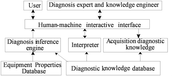
2.2. Diagnostic reasoning engine
Diagnostic reasoning engine is used of the fault knowledge of diagnostic knowledge base, according to a certain reasoning strategies to infer for the input data, draw conclusions. Diagnostic knowledge base and diagnostic reasoning engine are the core equipments of diagnostic system.
2.3. Equipment property database
Equipment property database is up with knowledge related to specific issues in diagnostic field and required and generated information when the system is running, including operating parameters, intermediate result, explain etc.
2.4. Diagnostic knowledge acquisition
Diagnostic knowledge acquisition is a transfer process of knowledge that from knowledge source (expert experience, books, and literature) to diagnostic knowledge base, but which need to constantly update and expansion, so it has become the bottleneck problem of expert system.
2.5. Explain module
Explain module is the explanation of knowledge, methods of dealt with problems, and the answers to the user questions, which realizes the system's transparency, and increases the acceptability of system.
2.6. Man-machine interface
Man-machine interface is the media of exchange information between system and users, users can provide diagnostic data, problems, and modify or expand the diagnostic knowledge base.
2.7. Framework of expert system
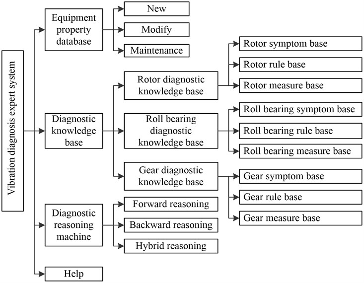
In this paper, the overall framework of expert system for vibration diagnosis of rotating machinery is shown in Fig. 2, including the four major parts that are equipment property database, diagnostic knowledge database, diagnostic inference engine, and help.
Fig. 2The overall framework of vibration diagnosis expert system
3. Database management
Database stores diagnostic knowledge of the important parts of rotating machinery, such as rotor, bearings, gears, including equipment property database and diagnostic knowledge base two parts. Device properties database put up calculation of each component failure frequency, diagnostic knowledge base is component failure characteristics, causes and measures.
3.1. Data tables
Equipment property database stocks parameters and fault frequency of rotor, bearing and gear, when the rotor speed is 3000 r/min, calculate failure frequency of each stage and store in the table rotor frequency, its structure shown in Table 1. Select bearing type is 18, the pitch diameter is 15 mm, diameter 4.67 mm, rolling number is 14, if the shaft speed is 3000 r/min, calculated the corresponding fault frequency and store bear frequency table as shown in the Table 2, the structure shown in Table 2. The number of Gear 1 (active gear) teeth is 17, speed is 3000 r/min, the number of Gear 2 (driven gear) teeth is 26, and the speed is 1961.53 r/min, the failure frequency table of gear frequency as shown in Table 3.
3.2. Diagnostic knowledge database
Diagnostic knowledge base store diagnostic knowledge obtained from the knowledge source in the form of production rules, as rotating machinery faults are more, in order not to duplicate or missing diagnostic knowledge, diagnostic knowledge base is divided into the rotor, bearings, gears three knowledge base, each of which has symptom database, rule database, measures database, the three sub-diagnostic knowledge base, for different object, as long as you can search for the appropriate diagnostic knowledge base.
3.2.1. Symptom database
The common failure characterization of components is stored in the symptom database. For the rotor, due to there are similar spectrum characteristics for multiple faults, so from the spectrum, wave, vibration trends to diagnosis, and for rolling bearings and gears, different faults have different spectral characteristics, it is only through the spectrum diagnosis.
The symptom table stored in the database consists of fact_id, fact_des, and mark as shown in Table 4.
Table 1Rotor frequency table
Field | Description |
Rotating speed | |
Fundamental frequency of rotor | |
0.2 harmonic frequency of rotor | |
0.43 harmonic frequency of rotor | |
Half harmonic frequency of rotor | |
0.67 harmonic frequency of rotor | |
0.8 harmonic frequency of rotor | |
Second harmonic frequency of rotor | |
Third harmonic frequency of rotor | |
Fourth harmonic frequency of rotor | |
Fifth harmonic frequency of rotor | |
Sixth harmonic frequency of rotor | |
Seventh harmonic frequency of rotor | |
Eighth harmonic frequency of rotor | |
Ninth harmonic frequency of rotor |
Table 2Bearing frequency table
Field | Description |
Rotating speed of shaft | |
Rotating frequency of shaft | |
Rotating frequency of bearing outer ring | |
Rotating frequency of bearing inner ring | |
Cage rotation frequency | |
Rolling rotation frequency of bearing | |
Sum of and | |
Difference between and | |
Sum of and | |
Difference between and | |
Sum of and | |
Difference between and | |
Sum of and | |
Difference between and | |
Sum of and | |
Difference between and |
Table 3Gear frequency table
Field | Description |
Rotating speed of shaft | |
Rotating frequency of shaft | |
Second harmonic frequency of shaft | |
Mesh frequency of gear | |
Second harmonic frequency of mesh | |
Sum of and | |
Sum of and | |
Difference between and | |
Difference between and | |
Sum of and | |
Difference between fg and | |
Sum of and | |
Difference between and |
Table 4The fields of symptom table
Field | Description |
fact_id | Symptom code |
fact_des | Symptom description |
mark | Activation marker, when the symptoms successful match, set to true |
3.2.2. Measure database
Measure database stock diagnosis conclusion that the fault type and the measures should be taken when failure. The measures table consists of conclusion_id, conclusion_name, measure, used as shown in Table 5.
Table 5The fields of measure table
Field | Description |
conclusion_id | Conclusion code that is fault code |
conclusion_name | Fault name |
measure | Measures to be taken after fault |
used | Activation marker, when the fault successful matches, set to true |
3.2.3. Rule database
The knowledge of rule database is meta-knowledge, which guide the diagnostic inference engine to search for symptom database, measure database, and expressed by production rules [5]. The structure of rule table is shown in Table 6.
In addition, temporary data tables that Temp is in the knowledge database, which used to store intermediate results, the structure is the same with rules table.
Table 6The fields of rule table
Field | Description |
rule_id | Rule number, expressed by RXX |
rule_code | Rule code, the same with the Symptom code |
conclusion_id | Conclusion code that is fault code |
used | Activation markers, when the rule successful matches, set to true |
4. Diagnostic inference engine
Diagnosis inference engine has forward reasoning, backward reasoning, and forward-backward hybrid reasoning. The system as needed, when forward reasoning based on the spectrum does not obtain the only conclusion, then reenter the vibration trend to backward reasoning, flow chart of hybrid reasoning as shown in Fig. 3, the inference steps are as following.
Fig. 3Flow chart of hybrid reasoning
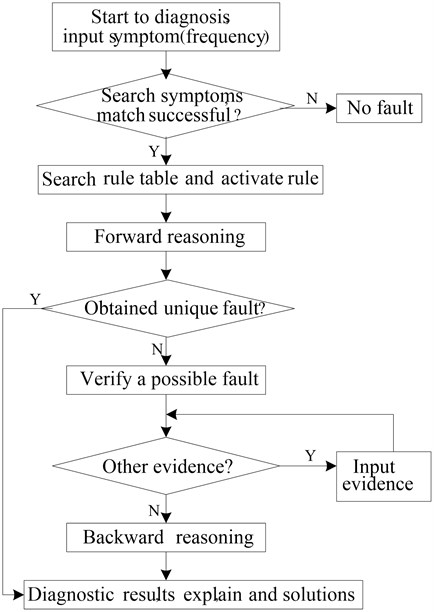
Step 1: Start to diagnosis used forward reasoning, input signal.
Step 2: Extract fault features in the spectrum, namely, the amplitude of different frequency and calculate percentage of frequency amplitude to the pass frequency amplitude.
Step 3: According to the percentage of the amplitude of each frequency, obtain the symptoms.
Step 4: Search for symptom table, when match successful, activate the symptom, mark is set to true, extract the fact_id.
Step 5: According fact_id that mark is true to search rules table, fact_id namely, rule_code, make all the complied rules activate, remove the conclusion_id, while the used set to true, then put them in Temp.
Step 6: If record of Temp is 1, stop reasoning, then go to Step 9, if the records of Temp are more than 1, go to Step 7, backward reasoning.
Step 7: Set activate mark in symptom table and rule table to false, select the first failure of Temp, extract conclusion_id, and make all the complied rules in the rule table activate, set used to true, extract rule_code which used is true, search for symptom table, as fact_id make fact_des activate, set mark to true.
Step 8: Input vibration trend, if signs and fact_des are all the same, stop reasoning, go to Step 9, if is not identical, then delete the first record of Temp, check the second, until the same, go to Step 9.
Step 9: Extract conclusion_id in Temp, search measure table concluded by the conclusion_id, extract conclusion_name, measure, and stop reasoning.
5. Applications
Based on the spectrum vibration diagnosis expert system, according to the spectrum, use of knowledge in the knowledge database, apply forward reasoning or the hybrid reasoning strategy, obtained fault and the measures, finally format a diagnostic report of the entire diagnostic process for later reference.
5.1. Case 1
Vibration characteristics of rotor gradual unbalanced is the fundamental frequency component is larger in failure frequency, fundamental frequency amplitude is greater than 70 % the passband amplitude, vibration gradually become larger with time.
Diagnostic process is as following.
Step 1: Input signal. The input analog signal is [6]:
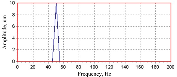
where, 50 Hz. Sampling of the signal by the sampling frequency 5120 Hz, then obtained spectrum shown in Fig. 4 by Discrete Fourier Transform (DFT).
Step 2: Extract feature. Automatically extracted fault feature from the spectrum, when the rotor speed is 3000 r/min, extract displacement amplitude for fundamental frequency (50 Hz) is 10 μm, the rest displacement amplitude of frequency, harmonic is zero, accounted for total passband amplitude is 100 %.
Step 3: Diagnostic reasoning. Forward reasoning diagnosis, resulting failure is not unique, need to backward reasoning, select vibration tendency is “The initial run low vibration, vibration gradually increased over time”, come to the fault of the rotor gradient balance.
Step 4: Maintenance decision-making and diagnostic reports. Measures should be taken are repair the rotor cleaning, regular maintenance, to ensure that the media clean, with no solution, to prevent scaling and corrosion.
The diagnosis object, method, basis, counter measures through the OLE component in the C++ Builder that connected to Word form a diagnostic report, which include Table 7 and Fig. 4.
Table 7Diagnostic report of rotor gradient unbalance
Items | Description |
Diagnostic object | Rotor |
Rotating speed | 3000 r/min |
Fault code and name | F03: Rotor gradient unbalance |
Explanation | Rotor vibration spectrum is 70 % |
Measures | Rotor cleaning, regular maintenance, to ensure that the media clean, with no solution, to prevent scaling and corrosion |
Fig. 4The spectrum of rotor gradient unbalance fault
5.2. Case 2
Outer corrugated pitting failure of rolling bear will appear sideband components intervals to the bearing rotation frequency around the outer ring frequency and its harmonic components.
Diagnostic process is as following:
Step 1: Input signal. Input analog signal is [7]:
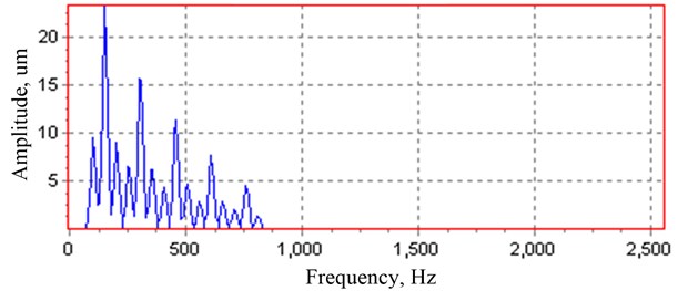
where, 50 Hz, 0.7, 0.6, 0.5, 0.4, 0.3, 1.3. The sampling of signal with the sampling frequency 5120 Hz, sampling points for 1024, the spectrum obtained by DFT is shown in Fig. 5.
Step 2: Feature extraction. When the bearings shaft speed is 3000 r/min, through rolling bear calculated frequency interface in the device property database, calculation of the outer ring fault frequency 152.35 Hz, inner ring fault frequency 247.6 Hz, rolling element fault frequency 99.05 Hz, cage rotation frequency 19.05 Hz, shaft rotation frequency 50 Hz, automatically extracted fault feature from the spectrum, displacement amplitude of (152.35 Hz) is 23.417 μm, (304.7 Hz) is 15.769 μm, (457.05 Hz) is 11.376 μm, the sideband frequency is 50 Hz.
Step 3: Diagnostic reasoning. Forward reasoning diagnosis, obtained for the outer corrugated fault, pitting.
Step 4: Maintenance decision-making and diagnostic reports. Measures are that according required designing and manufacturing bearings, reducing the residual ripple finish, to improve the seal, prevent rust when stopping, use the appropriate viscosity lubricant, to improve the lubrication.
Diagnostic report is as shown in Table 8 and Fig. 5.
Table 8Diagnostic report of bearing fault
Items | Description |
Diagnostic object | Rolling bear |
Rotating speed | 3000 r/min |
Failure frequency | 50 Hz, 152.35 Hz, 247.6 Hz, 99.05 Hz, 19.05 Hz |
Fault code and name | F07: outer ring corrugated fault, pitting |
Explanation | Characteristic frequency is |
Measures | According required to design, manufacture bearings, reducing the residual ripple finish, use the appropriate viscosity lubricant |
Fig. 5The spectrum of bearing fault.
From above two examples, drawn diagnosis results are consistent with the theory, indicating that diagnostic accuracy in the system.
6. Conclusions
The paper discussed a spectrum-based expert system for vibration diagnosis of rotating machinery, firstly, the overall structure of diagnostic system and design expert system structure in the paper are introduced, and then focuses on the database (equipment property database, diagnostic knowledge base), diagnostic inference, equipment property database storage device basic parameters and calculated failure frequency of each component based on the basic parameters for diagnostic use; diagnostic knowledge base taking into account convenience store and search for the spectral characteristics, using the structural design in the paper; diagnostic reasoning machine select forward reasoning, or hybrid reasoning based on symptom, finally through diagnosis examples of the rotor, bearing to illustrate the scientific and rational in the system design, accuracy in the diagnosis.
References
-
Han J., Zhang R. L. Failure mechanism and diagnosis technology of rotating machinery. Mechanical Industry Press, Beijing, 1997, (in Chinese).
-
Li X., Luo X. K., Zhang Z. Y. Development of an expert system based on fault diagnosis of rotating machinery experiment. Equipment Manufacturing Technology, Vol. 2, 2009, p. 108-111, (in Chinese).
-
Zhang J., Gao X. J., Yao J. B., Zhang Z. Technology of expert system based on neural network. Journal of Jilin University (Information Science Edition), Vol. 3, 2009, p. 319-324, (in Chinese).
-
He Q., Li X. Q. Management of knowledge base of expert system for fault diagnosis of rotating machinery. Applied Mechanics and Materials, Vol. 44-47, Part 3, 2011, p. 2935-2939.
-
Lei Y. G., He Z. J., Zi Y. Y. A new approach to intelligent fault diagnosis of rotating machinery. Expert System with Applications, Vol. 35, Issue 4, 2008, p. 1593-1600.
-
Wang Y. F., Xie Y. P. Fault diagnosis and analysis of rotor imbalance of rotor machinery. Journal of Hunan Industry Polytechnic, Vol. 9, Issue 5, 2009, p. 6-7, (in Chinese).
-
Fan Y. S. Modern Signal Processing Methods of Machinery and Equipment Diagnosis. China National Defence Industry Press, Beijing, 2009, (in Chinese).
About this article

