Abstract
The load on conical pick is affected by many factors such as pick geometry and installation angle. In order to decrease the wear and vibration of pick in the cutting process by choosing proper impact angle, the interference mathematical models of straight and revolving cutting were established according to coal cutting theory. Based on this, coal cutting experiment was carried out with different impact angles , different head face radii of pick body and different cutting depths to verify the mathematical model. The results indicate that the picks cutting into coal with a certain installed angle are prone to interfere with coal in the cutting progress. There is a crsitical impact angle, and it is different under different cutting conditions. The critical impact angle decreases with the head face radius of pick body and cutting depth . On the condition of given pick geometry and movement parameters, the cutting force of picks or cutting torque of cutting header decreases with the impact angle. When the impact angle of the pick is larger than the critical angle, the load on pick will increase prominently.
1. Introduction
Conical pick is mainly used on the cutting mechanism of shearer, heading machine and rotary drilling machine. Its performance directly impacts the production capacity, power assumed, the stability of machine and the life of other components. The load on picks is not only influenced by external factors such as working condition, coal seam condition and cutting technique but also influenced by internal factors such as geometry parameters, materials and install angle [1-5].
Using different researching methods, many scholars have studied the influence of different factors on picks load in order to decrease the wear and vibration of pick in the cutting process. O. Z. Hekimoglu studied the influence of vane wrap angle of shearer drum on cutting performance of drum stating that excessive vane wrap angle increased the cutting resistance and was detrimental to cutting performance [6]. Bo Yu simulated the coal cutting progress and studied the influence of cutting parameters, pick geometry and effect among picks on drum load using LS-DYNA [7]. R. M. Goktan researched the cutting forces under varying cutting geometries by means of a semi-empirical approach and developed prediction equations of the peak cutting force and mean cutting force shown statistically significant by the regression analysis through analyzing the full-scale rock cutting test data [8]. E. Mustafa Eyyuboglu studied effects of equal and unequal circumferential pick spacing on the performance of cutting mechanism and pointed out that no significant difference exists [9]. N. Bilgin studied dominant rock properties affecting the performance of picks load and emphasized that uniaxial compressive strength among the rock properties investigated is best correlated with the measured cutter performance values [10]. Brijes Mishra used finite element analysis and Automated Rotary Coal Cutting Simulator (ARCCS) to investigate the effect of pick design and drum design on heat development of pick, cutting forces, specific energy and respirable dust generation and emphasized the change in the size and shape of the bit tip increased the performance of the cutting system and the cutting performance of the Khair bit was better than bits used for comparison [11]. Du established a mechanical model and computing formula for a pick, the drum load fluctuation model and optimal mathematical model for drum pick arrangements to obtain relationships between pick arrangements with different start vanes and drum fluctuation loads, drum rotary speeds and haulage speeds [12]. Liu carried out cutting tests on an established cutting test bed to analyze the relationship between cutting force and coal compressive strength, the carbide tip diameter and the cutting depth and study the relationships between the type of pick arrangements and the cutting lump coal percentage. The results show that the cutting force is linearly related to the compressive strength. The relationship between the cutting force and both the carbide tip diameter and the cutting depth are exponential and the punnett square drum is superior to the sequence drum [13-15]. Using the perturbation techniques, Sahebkar S. M. developed the nonlinear model for a drill-rod system in deviated well with axially moving motion and axial loading, and the effects of rotating speed, axial compression load, imbalance mass and nonlinear fluid force on the drill-rod responses were investigated in detail, nonlinear natural frequencies and their corresponding mode shapes were presented [16]. Gulyayev V. I. took the problems on investigation of the dynamic bending of elongated drill-rod tubes into consideration, which indicated that the free bending vibrations of unbounded rods could be realized only in the modes of regular dextral and sinistral spiral waves propagating with different velocities in different directions [17]. Kreuzer E. presented a method for controlling the torsional and stick-slip vibrations by exactly decomposing the drill string dynamics into two traveling waves traveling in the direction of the top drive and in the direction of the drill-bit [18].
The above researches provide the references for this study. But there is still little expert study on the interference model between coal and picks. According to coal or rock cutting theory, this paper deduced the critical angle of picks in the cutting progress and then carried out experimental study to obtain significant conclusions which could guide the design of picks and its install angle to make up coal or rock cutting theory.
2. Interference model
There are mainly two working forms for conical picks currently, straight cutting and revolving cutting. The interference models for that two working forms were established as follows.
2.1. Straight cutting
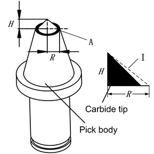
Fig. 1 shows pick in straight cutting. As shown in Fig. 1, is the impact angle. It is between the pick axis and the vertical direction of cutting movement. is the height of carbide tip, is head face radii of pick body, as shown in Fig. 2.
Fig. 1Pick in straight cutting
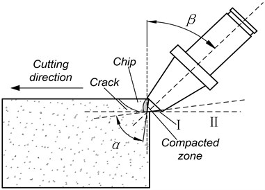
Fig. 2Conical Pick
The head face “A” of pick-body (Fig. 2, colored black) interferes with coal firstly and the critical condition of interference is that instantaneous movement direction II of pick-tip is coincident with the line I. Supposing the head face “A” of pick-body is on the critical condition of interference with coal, should satisfy Eq. (1) according to geometry relation:
It is hard to say that the pick did not interfere with coal in the cutting process when only Eq. (1) was satisfied. Supposing that ‘V’ shaped groove formed on coal under the action of pick, the head face of pick body “A” was projected into the vertical plane of movement direction, shown in Fig. 3. There are three relative locations between the projected ellipse and ‘V’ shaped groove. is the caving angle. Fig. 3(a) shows the critical position that the pick happened to interfere with coal. When the caving angle is not big enough, the pick interferes with coal. And the caving line I cuts the ellipse at two points and , as shown in Fig. 3(b). On the contrary, the pick does not interfere with coal, as shown in Fig. 3(c).
Fig. 3Relative location between the projected ellipse and ‘V’ shaped groove
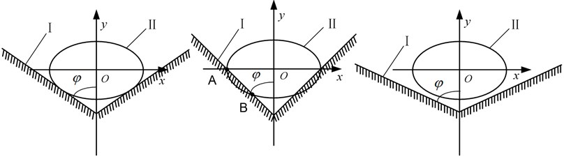
(a) (b) (c)
Axes coordinate system was established with the origin at the center of the ellipse ‘’. Eq. (2) and Eq. (3) gives the formula of caving line I and ellipse II respectively:
The pick interfering coal or not is judged by whether Eq. (2) and Eq. (3) have the same answers. Thus the condition of no interference is given as:
Eq. (5) and Eq. (6) are obtained by combining Eq. (2) and Eq. (3) according to Viete's theorem:
Then the secant length (distance between point and ) is calculated by Eq. (7):
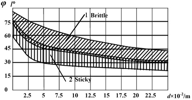
where the proper angle could be chosen according to the relationship between caving angle and cutting depth, as shown in Fig. 4.
Fig. 4Relationship between caving angle and cutting depth
2.2. Revolving cutting
Fig. 5 shows pick in revolving cutting. The impact angle is between the pick axis and the line from pick-tip to the center of cutting header. The head face “A” still interferes with coal firstly and the critical condition of interference is that instantaneous movement direction II of pick-tip is coincident with line I.
Fig. 5Pick in revolving cutting
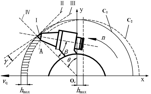
Line III is the tangent of pick instantaneous rotary movement which is perpendicular to the line from pick-tip to drum center and at an angle to instantaneous movement direction II. is the advancing velocity. is the rotating speed. is the maximum cutting thickness.
Supposing the head face “A” of pick-body is on the critical condition of interference with coal, should satisfy Eq. (8) according to geometry relation:
where is related to advancing velocity and rotating speed of the pick.
where is the distance between pick-tip and the center of cutting header.
Similarly, it would not be ensured that the pick did not interfere with coal in the cutting process when only Eq. (8) was satisfied. When the head face of pick body “A” was projected into the vertical plane of movement direction, there are still three relative locations between the projected ellipse and ‘V’ shaped groove. The condition of no interference and the secant length are given by Eq. (10) and Eq. (11) respectively:
The pick critical impact angle obtained according to Eq. (4) and Eq. (10) means that the head face “A” of pick-body will interfere with coal if the pick critical impact angle is larger than the pick impact angle on the condition of given pick geometric parameters and movement parameters.
What’s more, the distinction between straight cutting and revolving cutting is that the cutting depth is always changing in the revolving cutting process, shown in Fig. 5. The cutting depth is changing from 0 to with the rotation angle changing from 0 to 90°. Axes coordinate system was established with the origin at the center of the circle ‘’. Angle is between line IV and -axis. In order to simplify the calculation, circle is regarded as an ellipse with point ‘’ as center. Then the formula of line IV, circle and circle are given as:
The maximum cutting thickness given by Eq. (15) according to the matching relation between advancing velocity and rotating speed of pick:
Supposing the cutting depth of pick is at one moment, and the formula of it is given as follows according to Eqs. (12-14):
The cutting depths can be calculated by Eq. (16) when angle is from 0-90°, which were used to choose caving angles in the revolving cutting process.
3. Numerical analysis
3.1. Straight cutting
The head face radii of pick body is supposed to be 10, 12, 14 and 16 mm, and cutting depth is 5 mm, 15 mm, 25 mm respectively. The caving angle chosen according to Fig. 4 and the critical impact angle calculated by Eq. (4) are shown in Table. 1.
From Table 1, it can be seen that the critical impact angle decreased with the head face radii of pick body and cutting depth. Compared with the head face radii of pick body, cutting depth influences less on the critical impact angle . The reason is that the caving angle changing with cutting depth.
Table 1Critical impact angle under different condition
Head face radii of pick body / mm | Cutting depth / mm | Caving angle / ° | Critical impact angle / ° |
12 | 5 | 80 | 44.2 |
12 | 10 | 75 | 43.0 |
10 | 15 | 70 | 47.2 |
12 | 15 | 70 | 41.3 |
14 | 15 | 70 | 36.2 |
16 | 15 | 70 | 31.7 |
12 | 25 | 65 | 38.8 |
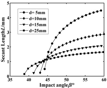
Fig. 6 and Fig. 7 show the secant length changing with the head face radii of pick body and cutting depth respectively. It can be seen that the secant length under different increases rapidly and then tends to stable amount. The head face radii of pick body has little effect on increasing rate of secant length and the stable amount. But the relative variation of secant length decreases greatly with the cutting depth . It should be paid more attention that the secant lengths under different cutting depths are incomparable.
Fig. 6Secant length L changing with R
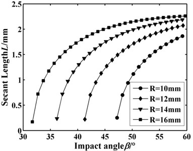
Fig. 7Secant length L changing with d
3.2. Revolving cutting
The head face radii of pick body is supposed to be 12 mm, the rotation speed is 60 r/min and the advancing velocity is 0 m/min, 0.5 m/min, 1 m/min and 2 m/min respectively. When the advancing velocity is 0 m/min, the cutting depth is a constant which is supposed to be 5 mm. The caving angle chosen according to Fig. 4 and the critical impact angle calculated by Eq. (10) are shown in Table 2.
Table 2Critical impact angle under different condition
Advancing velocity m/min | Maximum cutting depth / mm | Caving angle / ° | Critical impact angle / ° |
0 | 5 | 80 | 44.2 |
0.5 | 8.3 | 75-80 | 42.8 |
1.0 | 16.7 | 70-80 | 40.2 |
2.0 | 33.3 | 65-80 | 35.4 |
To avoid the interference between the pick and coal entirely, no interference for the pick under maximum cutting depth must be satisfied. Thus the critical impact angle is 44.2°, 42.8°, 40.2° and 35.4°, when the advancing velocity is 0 m/min, 0.5 m/min, 1 m/min and 2 m/min respectively. The critical impact angle decreases with the advancing velocity.
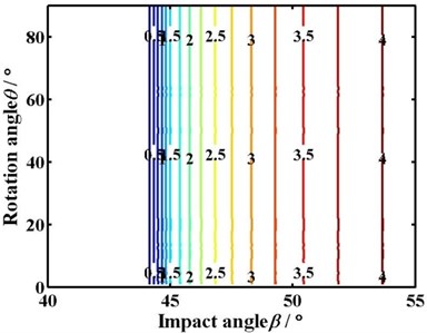
The contour of the secant length according to the Eq. (11) is shown in Fig. 8. It shows the influence of rotation angle and impact angle on the secant length.
Fig. 8Contour of the secant length
(a) 0 m/min
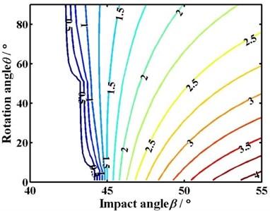
(b) 0.5 m/min
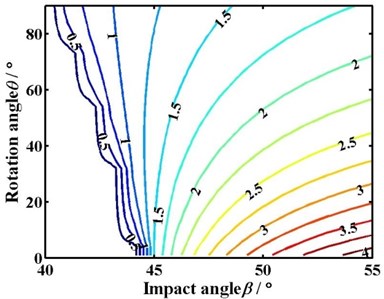
(c) 1.0 m/min
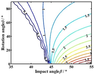
(d) 2.0 m/min
The blank area in Fig. 8 means that the pick does not interfere with coal in the cutting process. The numeral on the curve means the value of the secant length. The blue curve whose value is 0.5 is the criticality of interference between the pick and coal. The sparser the contour is, the greater the change of secant length is, and vice versa.
The critical impact angle and the increasing rate of secant length with impact angle does not change with the rotation when the advancing velocity is 0 m/min, as shown in Fig. 8(a). While the advancing velocity is not 0 m/min, the critical impact angle decreases with the rotation angle. Moreover, the range of the critical impact angle increases from 1.4° to 8.8° with the advancing velocity changing from 0.5 m/min to 2 m/min. The smaller the rotation angle is, the denser the contour and the greater the change of secant length is. On the contrary, the bigger the rotation angle is, the sparser the contour and the smaller the change of secant length is.
On the other hand, under the same rotation angle, the contour of secant length becomes sparse and the change of secant length decreases with the impact angle. Meanwhile, the secant length under different impact angles is comparable. The bigger the impact angle is, the greater the secant length is.
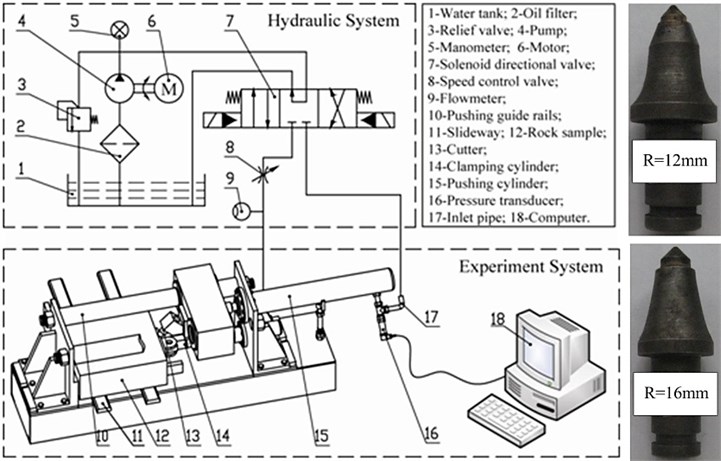
4. Experimental
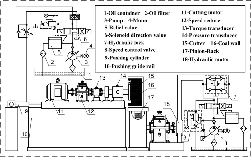
To verify the correctness and reliability of the theoretical model, the experiments of rock cutting were carried out. The straight and revolving rock cutting test-beds were shown in Fig. 9 and Fig. 12. The compressive strength of the analogy rock sample (Fig. 9) or coal wall (Fig. 12) is 1.97 MPa.
Fig. 9 shows that the rock sample is fixed on the test-bed by the clamping cylinder. The slideway can reduce the friction between the rock sample and test-bed, and make the loading-unloading and moving of the rock sample easily. The linear reciprocating cutting of the pick can be realized by the pushing cylinder and pushing guide rails. The cutting depth can be increased by adding steel sheets under the rock sample. The change of oil pressure in the pushing cylinder is measured by the pressure transducer JNBP-30 installed on the inlet pipe of the pushing cylinder. The cutting force is acquired according to the measured oil pressure.
The advancing velocity was set to be 4 m/min, the head face radii of pick body was 12 mm or 16 mm, and cutting depth was 5 mm or 25 mm, the impact angle was 30°, 35°, 40°, 45° or 50° respectively. The cutting force under different conditions are shown in Fig. 10.
Fig. 9Straight cutting test-bed
From Fig. 10, the amplitude and fluctuation of cutting force are different under different conditions. The greater the head face radii of pick body and cutting depth , the bigger the amplitude and fluctuation of cutting force. The amplitude and fluctuation are both relatively small when the impact angle is close to the criticality.
But the influence of impact angle on the mean cutting force is not obvious from Fig. 10. The relevant critical impact angle cannot be found correctly. Therefore the mean cutting forces under different conditions are calculated. The caving angle chosen according to Fig. 4, the critical impact angle calculated by Eq. (4) and the mean cutting forces are shown in Table 3.
Table 3Theoretical and experimental results of straight cutting
Head face radii of pick body / mm | Cutting depth / mm | Theoretical value | Mean cutting force / N | |||||
Caving angle / ° | Critical impact angle / ° | 30° | 35° | 40° | 45° | 50° | ||
12 | 5 | 80 | 44.2 | 451 | 443 | 405 | 323 | 490 |
16 | 5 | 80 | 35.8 | 596 | 567 | 552 | 613 | 665 |
12 | 25 | 65 | 38.8 | 2071 | 2055 | 2037 | 2045 | 2093 |
Fig. 10Cutting force under different conditions (minimum mean cutting force colored blue)
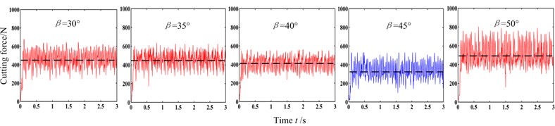
(a) 12 mm, 5 mm
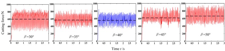
(b) 16 mm, 5 mm
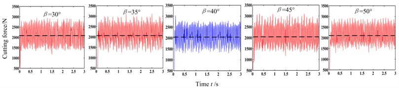
(c) 12 mm, 25 mm
The curves of mean cutting force under different cutting conditions are obtained by interpolating and fitting the data in Table 3, shown in Fig. 11.
Fig. 11 shows the influence of the head face radii of pick body and cutting depth on the curves of mean cutting force. The greater the and , the bigger the mean cutting force with different impact angles, which results from the increasing of interference between pick and coal. The critical impact angles under that three conditions are 45.4°, 38.6° and 41.6° respectively, generally in agreement with the theoretical ones 44.2°, 35.8° and 38.8°. But the critical impact angles from experiments are slightly greater which is mainly due to the selection error of caving angle. The changes of and result in 6.8° and 3.8° changes in the critical impact angle respectively, which indicates that the critical impact angle is little effected by cutting depth and the bigger the and , the easier the pick to interfere with coal.
Moreover, the bigger the and the less the relative change rate of mean cutting force, the less obvious the critical impact angle, which agrees well with theory.
Fig. 11Mean cutting force
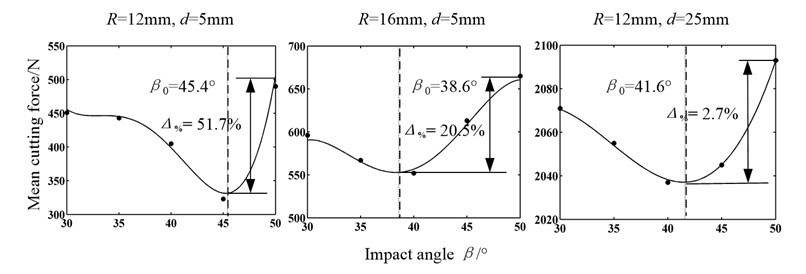
Fig. 12 shows a cutter with a single pick installed on the revolving cutting test-bed. The distance from pick-tip to the center of cutter is 0.25 m. The cutter was driven by the cutting motor. And the advancing velocity was controlled by the hydraulic motor. The torque of cutter was tested by torque transducer in the cutting process, which provided a indicator of the load on pick.
The advancing velocity was set to be 0.5 m/min or 2 m/min, the head face radii of pick body was 12 mm, and the impact angle was 30°, 35°, 40°, 45° or 50°. The cutting torques of under different conditions are shown in Fig. 13.
Fig. 12Revolving cutting test-bed
The cutting depth first increases and then decreases in the revolving cutting process, and the load on pick changes correspondingly. From Fig. 13, the amplitude and fluctuation of cutting torque are different under different conditions. The cutting torque and the difference between the peak and mean is relatively small when the impact angle is close to the criticality. Moreover, the cutting torque increases distinctly with the advancing velocity.
Fig. 13Cutting torque under different conditions (minimum mean cutting torque colored blue)
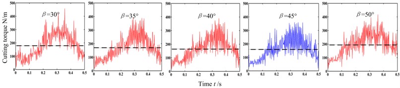
(a) 0.5 m/min
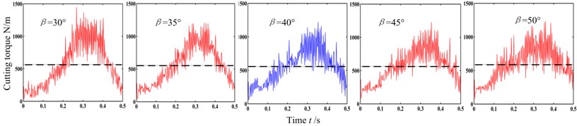
(b) 2.0 m/min
Table 4Theoretical and experimental results of revolving cutting
Advancing velocity / min | Theoretical value | Mean cutting torque / m | ||||||
Maximum cutting depth / mm | Caving angle / ° | Critical impact angle / ° | 30° | 35° | 40° | 45° | 50° | |
0.5 | 8.3 | 75-80 | 42.8 | 179 | 169 | 165 | 158 | 195 |
2 | 33.3 | 60-80 | 35.4 | 566 | 555 | 553 | 564 | 590 |
In order to research the influence of impact angle on the cutting torque and find the relevant critical impact angle, the mean cutting torques under different conditions are calculated. The caving angle chosen according to Fig. 4, the critical impact angle calculated by Eq. (10) and the mean cutting force are shown in Table. 4
Similarly, the curves of mean cutting torques under different cutting conditions are obtained by interpolating and fitting the data in Table 4, shown in Fig. 14.
Fig. 14Mean cutting torque
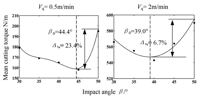
Fig. 14 shows the influence of advancing velocity on the curves of mean cutting torque. The greater the advancing velocity, the bigger the mean cutting torque with different impact angles, which is due to the increasing of cutting depth. The critical impact angles under that two conditions are 44.4° and 39.0°respectively, generally in agreement with the theoretical ones 42.8° and 35.4°. But the critical impact angles from experiments are greater which mainly results from two reasons. On one hand, it is due to the selection error of caving angle. On the other hand, it is not necessary to choose the impact angle that no interference between pick and coal under maximum cutting depth was satisfied as the criticality because it is just a moment on maximum cutting depth. The changes of advancing velocity result in 5.4° changes in the critical impact angle, which indicates that the advancing velocity really has some influence on the critical impact angle.
Moreover, the bigger the advancing velocity, the less the relative change rate of mean cutting torque, the less obvious the critical impact angle, which agrees also well with theory.
Furthermore, Fig. 11 and Fig. 14 witness that the mean cutting force or torque decreased with the impact angle when the impact angle is less than the critical angle. But it increased distinctly with the impact angle more than the critical angle, which is due to the interference between pick-body head face “A” and coal. And the main factor on the mean cutting force or torque is no longer the impact angle but the angle between the line I and instantaneous movement direction II. The greater the angle, the larger the load on pick.
5. Conclusions
(1) The theoretical and experimental researches indicate that the critical impact angle decreases with the head face radius of pick body and cutting depth . That means the bigger the head face radius of pick body and cutting depth , the easier the pick to interfere with coal. The critical impact angle is greatly influenced by head face radius of pick body , while little by cutting depth . The reason is that the caving angle changing with cutting depth.
(2) The secant length under different and increases rapidly and then tended to stable amount. The head face radius of pick body has little effect on the increasing rate of secant length and the stable amount. But the relative variation of secant length decreases greatly with the cutting depth .
(3) The cutting force of picks or cutting torque of cutter decreases with the impact angle when the impact angle is less than the critical angle on the condition of given pick geometry and movement parameters. But it would increase distinctly with the impact angle more than the critical angle and this is due to the interference between pick-body head face “A” and coal. And the main factor on load is no longer the impact angle but the angle between the line I and instantaneous movement direction II. The greater the angle, the larger the load on pick.
(4) The cutting depth is always changing with the revolving angle in the revolving cutting process with advancing velocity. The critical impact angle decreases with the rotation angle and the bigger the rotation angle is, the sparser the contour and the smaller the change of secant length is. Moreover, the critical impact angle decreases with the advancing velocity.
References
-
K. G. Hurt, K. M. MacAndrew Cutting efficiency and life of rock-cutting picks. Mining Science and Technology, Vol. 2, Issue 2, 1985, p. 139-151.
-
Liu Chunsheng, Yu Xinwei, Ren Changyu Work unit of shearer. Harbin Engineering University Press, 2010, (in Chinese).
-
Kuidong Gao, Changlong Du, Songyong Liu, et al. Model test of helical angle effect on coal loading performance of shear drum. International Journal of Mining Science and Technology, Vol. 22, Issue 2, 2012, p. 165-168.
-
Liu Songyong, Du Changlong, Zhang Jiajia, et al. Parameters analysis of shearer drum loading performance. Mining Science and Technology, Vol. 21, Issue 5, 2011, p. 621-624, (in Chinese).
-
Luo Yong, Zhang Dekun, Wang Qingliang, et al. Preparation and properties of a new cutting pick of coal shearers. Mining Science and Technology, Vol. 20, Issue 5, 2010, p. 794-796, (in Chinese).
-
O. Z. Hekimoglu, L. Ozdemir Effect of angle of wrap on cutting performance of drum shearers and continuous miners. Mining Technology, Vol. 113, 2004, p. 118-122.
-
Bo Yu Numerical Simulation of Continuous Miner Rock Cutting Process. Ph. D. Dissertation, College of Engineering and Mineral Resources at West Virginia University, 2005.
-
R. M. Goktan, N. Gunes A semi-empirical approach to cutting force prediction for point-attack picks. The Journal of the South African Institute of Mining and Metallurgy, Vol. 115, 2005, p. 257-263.
-
E. Mustafa Eyyuboglu, Naci Bolukbasi Effects of circumferential pick spacing on boom type roadheader cutting head performance. Tunnelling and Underground Space Technology, Vol. 20, 2005, p. 418-425.
-
N. Bilgin, M. A. Demircin, H. Copur, et al. Dominant rock properties affecting the performance of conical picks and the comparison of some experimental and theoretical results. International Journal of Rock Mechanics & Mining Sciences, Vol. 43, 2006, p. 139-156.
-
Brijes Mishra Analysis of Cutting Parameters and Heat Generation on Bits of a Continuous Miner Using Numerical and Experimental Approach. Ph. D. dissertation, College of Engineering and Mineral Resources at West Virginia University, 2007.
-
Du Changlong, Liu Songyong, Cui Xinxia, et al. Study on pick arrangement of shearer drum based on load fluctuation. Journal of China University of Mining and Technology, Vol. 8, Issue 2, 2008, p. 305-310.
-
Liu Songyong, Du Changlong, Cui Xinxia Research on the cutting force of a pick. Mining Science and Technology, Vol. 19, Issue 4, 2009, p. 514-517, (in Chinese).
-
Liu Songyong, Du Changlong, Cui Xinxia Experimental research on picks arrangement of shearer drum. Journal of Central South University, Science and Technology, Vol. 40, Issue 5, 2009, p. 1281-1287.
-
Liu Songyong, Du Changlong, Cui Xinxia, et al. Model test of the cutting properties of a shearer drum. Mining Science and Technology, Vol. 1, 2009, p. 74-78, (in Chinese).
-
Sahebkar S. M., Ghazavi M. R., Khadem S. E., Ghayesh M. H. Nonlinear vibration analysis of an axially moving drillstring system with time dependent axial load and axial velocity in inclined well. Mechanism and Machine Theory, Vol. 46, 2011, p. 743-760.
-
Gulyayev V. I., Borshch O. I. Free vibrations of drill strings in hyper deep vertical bore-wells. Journal of Petroleum Science and Engineering, Vol. 78, 2011, p. 759-764.
-
Kreuzer E., Steidl M. Controlling torsional vibrations of drill strings via decomposition of traveling waves. Arhive of Applied Mechanics, Vol. 82, 2012, p. 515-731.
About this article

This project is supported by National High-Tech Research and Development Program of China (863 Program) (No. 2012AA062102), National Natural Science Foundation of China (No. 51375478), and the Jiangsu Provincial Natural Science Foundation of China (No. BK20131116).
