Abstract
A spring-mass suspension is proposed in this paper for enhancing vibration energy harvesting performances of piezoelectric cantilevers. The suspension is inserted between the piezoelectric cantilever and the vibration base. Two key criteria are proposed for designing the present structure towards simultaneous broadband and intensive energy harvesting. On the one hand, the natural frequency of the spring-mass suspension is tuned close to that of the piezoelectric beam. On the other hand, the inertial mass of the suspension is chosen much greater than the cantilever mass. The amplification of the dynamic response over a broader frequency band of the proposed configuration is validated via vibration analyses. A prototype device in accordance with the proposed design is subsequently developed for experimental evaluations. The present structure widens the effective bandwidth from 7.6 Hz to 22.2 Hz, while increasing the maximum harvested power from 0.01436 mW/g to 0.4406 mW/g compared to the conventional cantilevered energy harvester.
1. Introduction
Vibration energy harvesters are promising devices in collecting electrical energy from environmental vibrations for powering miniature systems. Different transduction principles such as electrostatic [1], electromagnetic [2], and piezoelectric [3] mechanisms have been applied to convert the available environmental vibrations into electricity. A variety of smart materials which used to be applied for actuators are currently suggested for generating electricity from vibrations. Among them the piezoelectric transducers have attracted the most attentions, owing to its simple structure and good harvesting efficiency [4]. Therefore, in this research we focus mainly on performance enhancement of the piezoelectric energy harvester using a suspension structure.
For the piezoelectric energy harvester, a cantilever beam with a tip mass at the end is the commonly-used transduction mechanism [5]. As the maximum vibration response leading to peak power to be harvested often occurs at the natural frequency of the cantilever, the effective working frequencies (or, bandwidth) for the cantilevered harvester are usually close to its fundamental resonance frequency. This implies that the cantilevered harvester is a narrowband device in terms of effective vibration bandwidth for energy harvesting. In addition, the vibration intensity is also limited by the weak environmental vibrations even if at the resonance frequency. Accordingly, considerable effort has been devoted to cantilever optimization in improving the energy harvesting performance in either broadening the harvesting bandwidth or amplifying the vibration response. Some researchers have focused on tuning the resonant frequency and augmenting the effective frequency response bandwidth [6-8]. Some other studies have reported either beam shape optimization or the use of location selection to amplify the vibration response so as to increase the energy harvesting capability of piezoelectric cantilevers [9-11]. The separate consideration on one of the aforementioned two directions improves the energy harvesting performance to a certain extent [12]; but simultaneous broadband and intensive vibration energy harvesting remains a challenging task in this field. It should be noted that the “broadband” and the “intensive” are relative terms in the context. The broader bandwidth means better adaptability to accommodate the vibration energy at different frequencies; and a large quantity of power can obviously be generated through amplified vibration response intensity of the piezoelectric beam.
For a tuned mass damper (TMD) system [13-15], the vibration response of a primary structure close to the resonant frequency can be suppressed by attaching a considerably small auxiliary system. The two-DOF vibration system is capable of transferring energy within the two subsystems. According to the law of energy conservation, the energy can be neither created nor destroyed. Therefore, the TMD suppresses the resonance of the primary structure at the expense of vibration amplification over a broader frequency range for the auxiliary mass [16, 17]. Although intensive and broadband vibration on the auxiliary structure is an undesired effect for vibration suppression of the TMD system, fortunately, it provides an interesting approach applied for enhancing the vibration energy harvesting performance. A double beam configuration has been reported for the dynamic amplification of energy harvesters [18]. An intermediate beam with a tip mass is employed as a dynamic magnifier to drive the piezoelectric cantilever beam [19]. In those cases, the internal damping of the intermediate beam may waste the transferred vibration energy and thus deteriorate the power generation performances. In addition, a cantilevered intermediate beam occupies a greater plane.
In this paper, a spring-mass system is proposed as an auxiliary structure to the cantilevered piezoelectric harvester. The proposed structure can be regarded as an inverse effect of the TMD system. The TMD concept is employed in this study to design equal response amplitude at the two resonant frequencies for the proposed structure. Our innovation here is taking advantage of a helical spring-mass system as a suspension to enhance the harvested power over a broader frequency range with negligible transmission damping. Compared with the conventional piezoelectric cantilevered harvesters, the proposed structure features better adaptability in that it can harvest much energy from the enhanced vibration response within a broader effective frequency range.
The rest of this paper is structured as follows. A schematic illustration with the design criteria for our concept is provided in Section 2. The simultaneous broadband and intensive vibration response is analyzed in Section 3, followed by experimental evaluations in Section 4. Some conclusions are drawn in Section 5.
2. Schematic illustration
A schematic of the proposed energy harvester with a spring-mass suspension is shown in Fig. 1(a). In this study, instead of being excited directly by the base vibration, a piezoelectric cantilever with a tip mass at the end is driven by a spring-mass suspension inserted between the vibration source and the piezoelectric cantilever. This suspension is composed of a suspension mass and a suspension spring (helical spring) in series. The two ends of the suspension spring are connected to the vibration base and the suspension mass respectively.
The proposed structure can be divided as two subsystems: the cantilever subsystem and the suspension subsystem. Unlike a double beam structure [18], the suspension vibration and the cantilever vibration in our structure are not in the same direction. For the cantilever subsystem as shown in Fig. 1(b), the equivalent dynamic parameters are given by [20, 21]:
where denotes the equivalent mass, the equivalent stiffness, the equivalent damping, the mass per unit length of the beam, the length of the beam, the inertial mass of the tip mass, the Young’s modulus of the beam, the area moment of inertia of the beam, and the damping ratio. The natural frequency of the cantilever subsystem is thus expressed as:
Fig. 1Proposed vibration energy harvester with a spring-mass suspension: (a) schematic; and (b) mechanical model
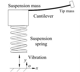
(a)
(b)
Next, both subsystems are considered as a whole to deduce the governing equations of the proposed structure. As shown in Fig. 1(b), let and denote the base displacement, relative displacement between the two ends of the suspension spring, and relative displacement between the tip mass and the suspension mass, respectively. The motions of the proposed energy harvester are governed by:
where and represent the suspension mass and the suspension stiffness, respectively, and the hat stands for the second order time derivative.
For a sinusoidal base excitation , the vibration response at the tip mass can be obtained from Eqs. (5) and (6) as:
It is a remarkable fact that there are two resonant frequencies and around the cantilever’s natural frequency . In previous investigations of the double-beam structure (e. g., [18]), the dynamic amplifications at these two resonant frequencies were not identical, which led to worse energy harvesting performance at one of the two resonant frequencies. To enhance the cantilever vibration, the following two functions are naturally anticipated: (1) at the two resonant frequencies, the vibration magnitudes should be amplified; and (2) the dynamic amplifications should be identical at the two resonant frequencies [22]. To this end, two parameter design criteria are proposed for realizing our concept:
• The suspension mass should be considerably greater than that of the cantilever system; and
• The natural frequency of the spring-mass suspension should be close to that of the cantilever system.
To formulate the above two criteria, we have:
where is a constant that is usually much greater than 1. The energy harvesting performance of a vibration energy harvester with a spring-mass suspension can be enhanced by using the aforementioned criteria. This can be preliminarily validated by the theoretical analyses presented in the following section.
3. Vibration response analyses
In this section, the vibration response analyses are conducted to theoretically prove that the present structure is capable of simultaneous broadband and intensive harvesting vibration energy. In other words, we tend to prove two lemmas in this section.
Lemma 1. The proposed harvester designed in accordance with Eqs. (8) and (9) exhibits two identical resonant peaks; while the conventional cantilevered has only one.
Proof 1. Substituting Eqs. (8) and (9) into Eq. (7) yields:
At the two resonant frequencies and , local maxima occurs for . This means:
Combining Eqs. (10) and (11) leads to closed forms of the two resonant frequencies ( and ) of the present structure:
Substituting Eqs. (12) and (13) into Eq. (10) results in the two maximum vibration response amplitudes:
Proved.
Hence, the suggested design criteria can guarantee the two equal dynamic amplifications at the two resonant frequencies and (i. e., anticipated function (2)). Hereafter, we will prove that the proposed design always features the amplification function for the maximum amplitude (anticipated function (1)).
To facilitate comparison between the proposed and the conventional vibration energy harvesters, we deduce the maximum vibration amplitude of the conventional one. For a conventional piezoelectric cantilever connected directly to the vibration base, the governing equation of the motion is given by:
where and respectively represent the corresponding vibration response and the base excitation of the conventional piezoelectric cantilever. Supposing the base excitation , can be extracted from the above equation as:
The resonant frequency of the conventional harvesting cantilever can be calculated and has been expressed in Eq. (4) as . Substituting Eq. (4) into Eq. (16) leads to the vibration response peak of the conventional piezoelectric cantilever:
To compare the vibration response peaks between the proposed and the conventional vibration energy harvesters, we have the following Lemma.
Lemma 2. The vibration response peaks of the proposed harvester designed in accordance with Eqs. (8) and (9) are always greater or equal to that of the conventional cantilevered harvester subject to same base excitations.
Proof 2. Relating Eq. (17) with Eq. (14) generates:
The partial derivative of the above equation is given by:
According to Eqs. (8) and (9), a is a constant that is usually much greater than 1. This ensures that 0. For an arbitrary positive real number , each items shown in the above equation are always positive, i. e., the above equation is always positive. This means that and are all monotonically increasing functions in relation to variable . The minima 0 results in the global minima of and at:
Comparing Eq. (20) with (17) indicates that the global minima of and is equal to the vibration response peak of the conventional piezoelectric cantilever. Therefore .
Proved.
Having proved Lemmas 1 and 2, the above theoretical analyses show that the proposed structure is capable of simultaneously amplifying the vibration magnitude and doubling the resonance peaks, as compared to the conventional cantilever. In addition to the theoretical analyses, experiments are carried out in the following section to show the performance enhancement of the proposed structure.
4. Experimental evaluations
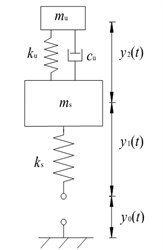
To further validate the performance enhancement of the proposed method in vibration energy harvesting, a prototype device was built at the Korea University in accordance with Fig. 1. A picture of the present prototype device with a spring-mass suspension is displayed in Fig. 2. As shown in Fig. 2, a bimorph (type T215-A4-103X, Piezo Systems Inc.) was employed as the piezoelectric beam, whose free end was attached to a tip mass. The other end of the piezoelectric beam was mounted on the top of a cubic mass, which is the suspension mass, as shown in Fig. 1(a). A helical spring was fixed to the bottom of the suspension mass. It should be noted that both the suspension mass and the beam length can be fine-tuned. Because a part of the beam length was employed for the installation, the effective length of the bimorph was less than its full length. In addition, four holes were machined on the two flanks of the suspension mass. This means that up to four screws can be added to the weight of the suspension mass.
Based on the parameter design criteria formulized by Eqs. (8) and (9), the detailed parameters of the prototype device are designed and listed in Table 1.
Fig. 2Prototype of the proposed harvester installed on the vibration exciter
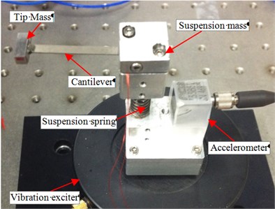
Table 1Geometric and material parameters of the prototype device
Nomenclature | Value | |
Inertial mass of suspension mass | 17.6×10⁻³ kg | |
Inertial mass of a screw | 0.21×10⁻³ kg | |
Suspension stiffness | 2×10³ N/m | |
Beam width | 3.2×10⁻³ m | |
Beam length (full length) | 31.8×10⁻³ m | |
Piezoelectric layer thickness | 0.15×10⁻³ m | |
Piezo Young’s modulus | 66×109 Pa | |
Piezo density | 7.8×10³ kg/m3 | |
Substrate thickness | 0.08×10⁻³ m | |
Substrate density | 9×10³ kg/m3 | |
Substrate Young’s modulus | 105×109 Pa | |
Inertial mass of tip mass | 1.5×10⁻³ kg | |
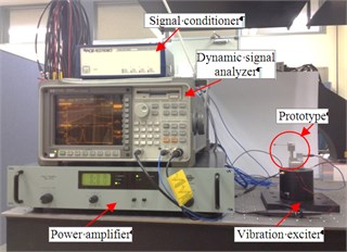
To characterize the enhancement of energy harvesting performance of the proposed vibration energy harvester, a test rig was built, following the measurement principle as shown in Fig. 3(a). In the experimental set-up, a vibration exciter (type 4810, Bruel and Kjar) was employed to generate the desired vibration source, which was predefined by a dynamic signal analyzer (type 35670A, HP) and driven by a power amplifier (type 2718, Bruel and Kjar). The harvester to be tested was connected to the output end of the vibration exciter through a host base that was also manufactured at the Korea University. To measure the real vibration produced by the vibration exciter, an accelerometer (type 333B52, PCB) was attached to the top of the host base. The measured vibration acceleration was conditioned using a signal conditioner (type 482C, Piezotronics) and then fed back to the dynamic signal analyzer. Two wires were connected to the two sides of the bimorph to monitor the harvested voltage, which was also acquired using the dynamic signal analyzer via a voltage probe (type P2220, Tektronix) whose internal resistance was measured as 585 kΩ. A picture of the experimental set-up is shown in Fig. 3(b).
Fig. 3Experimental system: (a) measurement circuit; and (b) overview of the set-up
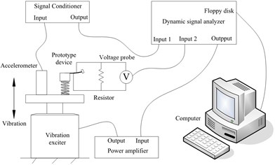
(a)
(b)
It should be noted that the prototype device shown in Fig. 2 can be transformed as a conventional vibration energy harvester without the suspension by removing the helical spring and mounting the suspension mass directly on the host base. To distinguish with the “prototype device” developed in accordance with the suspension idea, we call this conventional device as “reference device” without suspension attached. The only difference between the prototype device and the reference device is that the suspension function was disabled in the reference device. Hence, we could directly compare the proposed structure with the conventional design by carrying out experiments on both the present prototype device and the reference device.
There were two input channels (input 1 and input 2 as shown in Fig. 3(a)) and one output channel available for the dynamic signal analyzer. We employed the output channel to generate a swept harmonic signal that ranged from 20 Hz to 100 Hz to drive the vibration exciter. There are two reasons for choosing this range. On the one hand, frequency band 20-100 Hz is a commonly researched range for piezoelectric energy harvesters. On the other hand, the fundamental natural frequency of the cantilever beam is tested as 48.8 Hz (also can be calculated using Eq. (4)). It is reasonable to investigate the vibration energy harvesting performance close to this frequency. Through trial-and-error procedure, we focused 20-100 Hz as the experimental range as it could completely cover the effective frequency band.
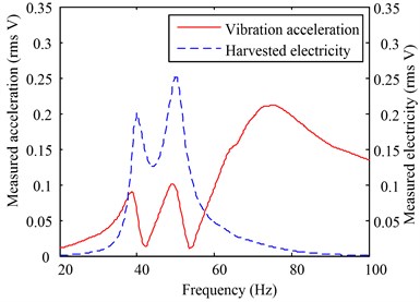
The rms signals of the base acceleration and the harvested voltage were collected using the two input channels. Fig. 4(a) shows the plot of the two signals collected by characterizing the prototype device. It is worth noting that the scale between the vibration acceleration and the measured signal is 9.8 m/s2 (1 g) vs. 1 V (all in rms). The two resonant peaks can be observed from the harvested electrical signal.
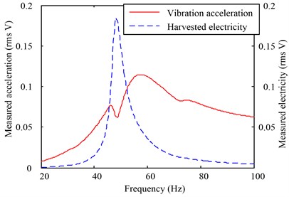
For comparison, a parallel experiment was carried out using the same test-rig. The swept harmonic signal was applied to the reference device again. The two input channel signals collected in the reference device experiment are displayed in Fig. 4(b). In Figs. 4(a) and 4(b), the vibration acceleration is not fixed. Instead, it seems to be variable in response to the output power. This is because the swept harmonic signal generated by the dynamic signal analyzer is open-loop controlled. A change in the output electricity (or vibration response) may lead to a fluctuation in the swept signal, which also reflects the harvested energy to a certain extent.
Because the two devices were tested under different vibration excitations, for fair comparison, we normalized the energy harvesting performances using the ratio between the vibration acceleration and the generated electricity. Let and denote the probed voltages from the characterization experiment and the reference experiment, respectively. The normalized voltages, i. e. and , are plotted in Figs. 5(a) and 5(b) respectively.
Fig. 4Experimental results for the two devices: (a) measured vibration acceleration and electricity signals obtained by characterizing the prototype device, and (b) measured vibration acceleration and electricity signals from the reference device experiment. The scale between the acceleration and the voltage is 9.8 m/s2 (1 g) vs. 1 V
(a)
(b)
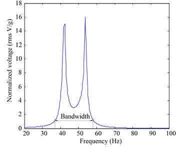
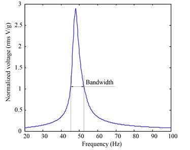
As shown in Fig. 5(a), the two peaks of the normalized voltage for the prototype device occur at 42.4 Hz and 53.6 Hz, which correspond to rms values of 15.06 V/g and 16.05 V/g, respectively. In contrast, Fig. 5(b) shows that there is only one rms peak (2.91 V/g), which occurs at 48.8 Hz, for the reference device (conventional harvesting cantilever). This indicates that the proposed structure (prototype device) provides an amplification of 552 % compared to the conventional one (reference device) in terms of the peak voltage at the resonant frequency. In the testing frequency range (20-100 Hz), according to the experimental results shown in Figs. 5(a) and 5(b), the proposed structure exhibits an average voltage increase of 441 % over that of the conventional harvester.
Fig. 5Voltage and bandwidth comparisons between the two devices: (a) normalized voltage and effective frequency bandwidth of the prototype device; and (b) normalized voltage generated and effective frequency bandwidth of the reference device. The effective bandwidth is chosen to be corresponding to normalized voltages greater than 1 V/g
(a)
(b)
Suppose the effective normalized voltage threshold is 1 V/g. It is shown in Fig. 5(a) that the bandwidth of the prototype device is 22.2 Hz (36.6 Hz~58.8 Hz). As shown in Fig. 5(b), on the contrary, the bandwidth is reduced as 7.6 Hz (45.0 Hz~52.6 Hz) for the reference device. Comparing Fig. 5(a) with Fig. 5(b) demonstrates that the proposed structure widens the effective vibration bandwidth by 292.11 %.
As the power index is more intuitional than the voltage for illustrating the enhancement of the energy harvesting performance, we also calculate the normalized powers, i. e. and , and plot them in Fig. 6. It is shown that the maximum power (normalized by the acceleration) of the proposed structure is 0.4406 mW/g; while that of the conventional device is 0.01436 mW/g. Hence the proposed design improves the maximum power by 3067 % comparing to the conventional piezoelectric cantilevered harvester. It is worth noting that the two power peaks for the prototype devices are not identical. The reason is that the power is proportional to the square of the voltage; and the small difference between the two voltage peaks are enlarged by the square calculation.
Fig. 6Comparison of harvested powers between the prototype device and the reference one
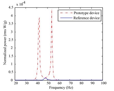
In addition to the maximum power comparison, one can also compare the mean harvested powers between the two experiments. It is calculated that, within the investigated frequency range (20 Hz-100 Hz), the present design exhibits a mean power improvement of 19.45 times compared to the reference device.
5. Conclusions
A broadband and intensive vibration energy harvester that employs a spring-mass system as the suspension is reported in this paper. Two criteria are presented for the parameter design of the system: the suspension mass should be considerably greater than that of the cantilever system and the natural frequency of the spring-mass suspension should be close to that of the cantilever system. Theoretical analyses proved that the present criteria were able to harvest vibration energy with broadband and intensive performance. A prototype device was subsequently developed in accordance with the design criteria. In comparison to the conventional device, the proposed configuration increased the peak voltage of the harvested power by up to 552 % and widened the effective frequency bandwidth by 292.11 %. In the tested frequency range (20-100 Hz), the average power increase resulting from the application of the suspension reached 1945 %, and the maximum power improved by 3067 % for the given case. Hence, the proposed method is capable of the simultaneous broadband and intensive harvesting of weak vibration energy. If two criteria are satisfied, a spring-mass suspension can be applied to a low-frequency micro vibration energy harvester or a package containing cantilevers and conditioning circuits. In addition to the piezoelectric transducer, ideas similar to the proposed spring-mass suspension could also be applied for enhancing other transduction structures such as electrostatic and electromagnetic energy harvesters.
References
-
Roundy S., Wright P. K., Rabaey J. A study of low level vibrations as a power source for wireless sensor nodes. Computer Communications, Vol. 26, Issue 11, 2003, p. 1131-1144.
-
Arroyo E., Badel A. Electromagnetic vibration energy harvesting device optimization by synchronous energy extraction. Sensors and Actuators A: Physical, Vol. 171, Issue 2, 2011, p. 266-273.
-
Li C., Hong D., Kwon K. H., Jeong J. Bond graph-based analysis of energy conversion in vibration-piezoelectricity coupling and its application to a cantilever vibration energy harvester. Journal of Vibroengineering, Vol. 14, Issue 2, 2012, p. 591-601.
-
Park C. H., Kim J. W., Lim J. H., Jeong S. S., Kim M. H., Park T. G. Increase of generating power of cantilever type piezoelectric generators by interconnecting the generators. Integrated Ferroelectrics, Vol. 134, Issue 1, 2012, p. 88-101.
-
Ambrosio R., Jimenez A., Mireles J., Moreno M., Monfil K., Heredia H. Study of piezoelectric energy harvesting system based on PZT. Integrated Ferroelectrics, Vol. 126, Issue 1, 2011, p. 77-86.
-
Wu H., Tang L., Yang Y., and Soh C. K. A Compact 2 degree-of-freedom energy harvester with cut-out cantilever beam. Japanese Journal of Applied Physics, Vol. 51, Issue 4, 2012.
-
Jang S. J., Rustighi E., Brennan M., Lee Y., Jung H. J. Design of a 2DOF vibrational energy harvesting device. Journal of Intelligent Material Systems and Structures, Vol. 22, Issue 5, 2011, p. 443-448.
-
Tang X., Zuo L. Enhanced vibration energy harvesting using dual-mass systems. Journal of Sound and Vibration, Vol. 330, Issue 21, 2011, p. 5199-5209.
-
Dietl J. M., Garcia E. Beam shape optimization for power harvesting. Journal of Intelligent Material Systems and Structures, Vol. 21, Issue 6, 2010, p. 633-646.
-
Xu J. W., Shao W. W., Kong F. R., Feng Z. H. Right-angle piezoelectric cantilever with improved energy harvesting efficiency. Applied Physics Letters, Vol. 96, Issue 15, 2010, p. 152904-152904-3.
-
Liu H., Lee C., Kobayashi T., Tay C. J., Quan C. A new S-shaped MEMS PZT cantilever for energy harvesting from low frequency vibrations below 30 Hz. Microsystem Technologies, Vol. 18, Issue 4, 2012, p. 497-506.
-
Kim I. H., Jung H. J., Lee B. M., Jang S. J. Broadband energy-harvesting using a two degree-of-freedom vibrating body. Applied Physics Letters, Vol. 98, Issue 21, 2011, p. 214102-214102-3.
-
Tigli O. F. Optimum vibration absorber (tuned mass damper) design for linear damped systems subjected to random loads. Journal of Sound and Vibration, Vol. 331, Issue 13, 2012, p. 3035-3049.
-
Luu M., Zabel V., Könke C. An optimization method of multi-resonant response of high-speed train bridges using TMDs. Finite Elements in Analysis and Design, Vol. 53, 2012, p. 13-23.
-
Moghaddas M., Esmailzadeh E., Sedaghati R., Khosravi P. Vibration control of Timoshenko beam traversed by moving vehicle using optimized tuned mass damper. Journal of Vibration and Control, Vol. 18, Issue 6, 2012, p. 757-773.
-
Lee C., Goda K., Hong H. Effectiveness of using tuned-mass dampers in reducing seismic risk. Structure and Infrastructure Engineering, Vol. 8, Issue 2, 2012, p. 141-156.
-
Weber F., Maślanka M. Frequency and damping adaptation of a TMD with controlled MR damper. Smart Materials and Structures, Vol. 21, Issue 5, 2012, p. 055011.
-
Li C., Hong D., Kwon K.-H., Jeong J. A multimode relayed piezoelectric cantilever for effective vibration energy harvesting. Japanese Journal of Applied Physics, Vol. 52, Issue 5, 2013, p. 0202.
-
Aldraihem O. and Baz A. Energy harvester with a dynamic magnifier. Journal of Intelligent Material Systems and Structures, Vol. 22, Issue 6, 2011, p. 521-530.
-
Erturk A., Inman D. A distributed parameter electromechanical model for cantilevered piezoelectric energy harvesters. Journal of Vibration and Acoustics, Vol. 130, Issue 4, 2008.
-
Ajitsaria J., Choe S. Y., Shen D., Kim D. Modeling and analysis of a bimorph piezoelectric cantilever beam for voltage generation. Smart Materials and Structures, Vol. 16, Issue 2, 2007, p. 447.
-
Krenk S., Høgsberg J. Tuned mass absorbers on damped structures under random load. Probabilistic Engineering Mechanics, Vol. 23, Issue 4, 2008, p. 408-415.
About this article

This work was supported in part by Basic Science Research Program through the National Research Foundation of Korea (NRF) Grant funded by the Ministry of Education, Science and Technology (MEST) (No. NRF-2010-0023337), the Natural Science Foundation of China (51375517), the Natural Science Foundation of CQ CSTC (2012JJJQ70001), and the Program for Chongqing Innovation Team in University (KJTD201313).
