Abstract
Combustion engines are one of the main sources of vibration and noise in vehicles. The level of engine vibroactivity is affected by aspects such as rotational speed and technical condition. Tests were carried out as part of the research, designed to assess the level of vibroactivity of SI engines in stationary and non-stationary conditions. During the bench tests, the engine’s rotational speed and its technical condition were changed by simulating a slightly enlarged valve clearance. As a result of the experiments it was determined that local changes in the amplitude of engine vibrations caused by the combustion process, clearances or misfire can be used as diagnostic information about the condition of the engine. It has been shown that the local level of vibration is dependent on the point of measurement, the angle of the crankshaft rotation and valve timing, and that for diagnostic tests, measurements performed in stationary engine operating conditions are more useful. The tests have also shown how the change of engine condition affects the level of noise and vibration generated, and how these levels change during the acceleration of the engine.
1. Introduction
Motor vehicles are major sources of vibration and noise in transport [1-9]. Sources of vibration and noise at low speeds of movement especially include the combustion engine and the transmission [10-20], wherein the level of the latter is much lower. At higher speeds of movement, a major role is played by aerodynamic noise and contact of the tyre with the road surface [21, 22]. Considering the possible the speed of the motor vehicle in city traffic – generally limited to 50 km/h, – it can be assumed that the dominant source of noise coming from the vehicle when moving in this area is the noise of the combustion engine.
Assessment of the level of vibroactivity of combustion engines allows for an investigation of the source of vibration and noise, which can be used for choosing the direction of future operations in regard to engine design changes as well as optimisation of the combustion process, such as in [18-20, 23]. These activities also allow for reducing the level of vibroactivity of combustion engines.
One of the directions of the use of vibro-acoustic signals generated by combustion engines is adaptation for diagnosing their condition [23-37]. The scope of use of the recorded vibro-acoustic signals is relatively new and is being extensively developed in many research and industry centres. In this case, procedures are being developed for conducting measurements and new methods of processing the recorded signals of vibration and noise generated by engines.
The use of a variety of vibro-acoustic signals in diagnosis of combustion engines was a topic of research by, among others, the authors of [23-27, 30-36]. The results of these experiments indicate that the diagnosis of engine condition can include vibration measurements using piezoelectric transducers, and noise measurements can be carried out using capacity microphones.
Diagnosis of the condition of combustion engines using vibro-acoustic signals recorded, however, requires the use of advanced signal processing methods. Thanks to the significant speed of personal computers and the development of data processing programs, such as Matlab-Simulink or Lab-View, it is now possible to create new tools for processing signals both in the time domain as well as time and frequency domain. The most popular methods for the analysis of signals include: fast Fourier transform, short-time Fourier transform, Wigner-Ville transform or wavelet transform. The results of using these methods can be found, among others, in [25-27, 31, 33-37].
So far, the results of tests conducted using measurements and processing of vibro-acoustic signals have enabled the detection of such engine damage as, for example, oversized clearance between the piston and the cylinder liner, bad condition of the belt tensioner in the timing system, burnt valves, or enlarged valve clearance.
An important issue that has not been fully explored is the change of the level of vibroactivity of combustion engines operating in stationary and non-stationary conditions, as well as the evaluation of the usefulness of signals recorded in these cases for diagnosis.
The paper presents the results of tests, the aim of which was to determine the changes of the level of vibroactivity of SI engines in stationary and non-stationary conditions. During the bench tests, the engine's rotational speed and its technical condition were changed by simulating a slightly enlarged valve clearance.
2. Bench tests and measurement system
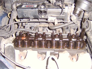
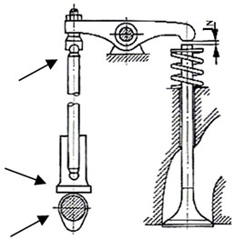
The subject of the study was a four-cylinder engine of a passenger car, with a spark ignition and cylinder capacity of 1.3 dm3. This engine is equipped with an eight-valve head and a camshaft located in the engine block (timing OHV). The test head engine with the disassembled valve cover and the possible places of the valve clearance there can decompose is shown on Fig. 1.
Fig. 1a) The test engine with the disassembled valve cover, b) Engine valve mechanism with the selected locations of the possible occurrence of valve clearance
a)
b)
For the test engine, the values of the opening and delayed closing time of the valves [38] are respectively: 18°, 38°, 45°, 7°. During the experiment, there was assumed the change in value of valve clearance - the exhaust and intake valves – increasing their value from the nominal clearance value. Adopted in this case the valve clearance values are shown in Table 1.
Table 1Valve clearance values used in the research
Valve | Test 1 | Test 2 | Test 3 |
Intake | 0.2 mm | 0.2 mm | 0.3 mm |
Exhaust | 0.5 mm | 0.6 mm | 0.5 mm |
Nominal clearance |
To diagnose valve clearance there was used a measuring system consisting of (Fig. 2):
1) Piezoelectric transducer.
2) Capacity microphone.
3) An optical sensor, which recorded the reference signal of crankshaft position.
4) National Instrument Data Acquisition Card NI 4472.
5) A computer with LabView 8.6 software.
Fig. 2Diagram of measurement system
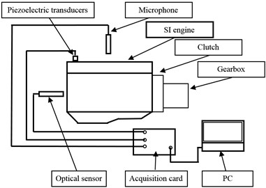
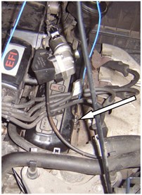
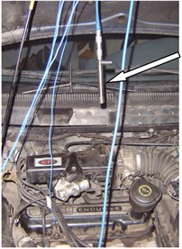
During the tests, the vibrations of the drive unit were recorded in the direction of movement of the piston. Measurements of the instantaneous acoustic pressure level were made at a distance of approximately 0.5 m above the engine valve cover.
The position of microphone and vibration acceleration is given on Fig. 3. Signals were recorded at a frequency of 25 kHz. Matlab-Simulink Signal Processing software was used for processing.
Fig. 3The location of acceleration transducer and microphone on the test engine
a)
b)
3. Results and discussion
3.1. Tests at idle speed of the engine
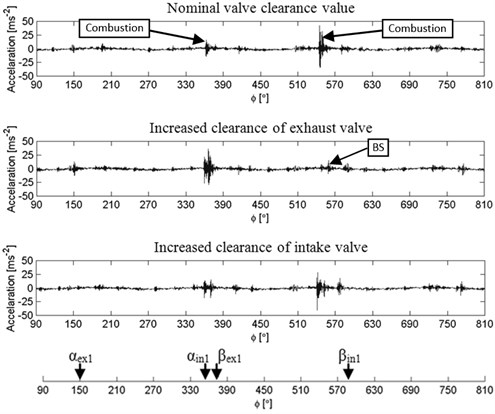
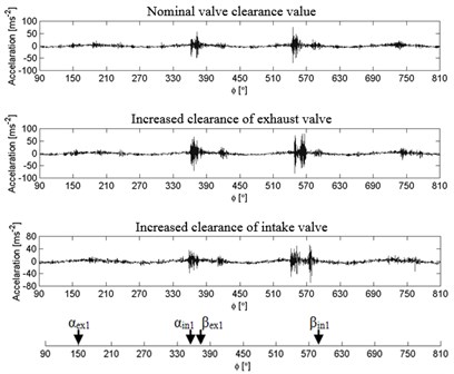
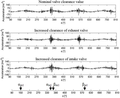
During the tests, momentary change of the vibration signal amplitude was evaluated at idle speed of the engine, in which there was valve clearance with a nominal value, as well as clearance of one exhaust and one intake valve increased by a small value. Selected non-averaged vibration signal waveforms recorded during these experiments are shown in Fig. 4.
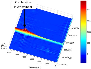
The measurements indicate that in the engine vibration signal with clearance at a nominal value we can be observe two local amplitude increases, which correspond to the process of combustion in cylinder 4th and 2nd of the engine. Other slight amplitude increases correspond to the process of combustion in the remaining cylinders and are the result of the clearances occurring in the engine, including valve clearances.
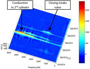
In the case of vibration signals recorded with an increased clearance in the intake and exhaust valves in the engine, we can further observe local signal amplitude increases at other positions of the crankshaft. The local amplitude increases of the vibration signal correspond in this case to range of the valve timing angles in case of valves with larger clearances. The amplitudes of vibration during the opening and closing of these valves are different. The vibration waveform shown in Fig. 4 has also made it possible to observe the misfire in cylinder 2nd, denoted BS, reflecting the damage of the ignition system in the tested engine.
Assessing the momentary change of vibroactivity of an engine at idle speed based on the waveforms, it can be concluded that the level of vibration varies locally depending on the angle of rotation of the crankshaft. The values of this change strongly depend on the transmission of vibrations in the engine from their source of generation to the point of measurement, on the clearances occurring in the engine and the proper operation of other engine systems, such as the ignition system.
Fig. 4Vibration waveform of an engine with nominal clearance, and with an increased clearance of the exhaust and intake valve, rotational speed ~873 rpm
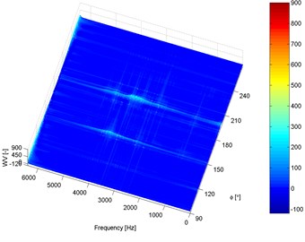
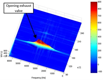
Vibration analysis with the use of time-frequency distributions is one of the methods of assessing the vibroactivity of mechanical systems. The use of these distributions enables the observation of local non-stationary changes in signal amplitude in terms of both time and frequency, and in some cases, isolation of characteristic frequency-dependent high frequency signal traits [27, 31, 34].
As part of the project, vibration signals shown in Fig. 4 have been processed by means of time-frequency Wigner-Ville distributions. These distributions were calculated in selected characteristic ranges of the rotation angle of the engine crankshaft, in which local changes in vibration amplitude were observed. Eq. (1) was used in the calculations:
where: – imaginary signal coupled to , – weight function.
The results of the calculations presented in Fig. 5 show that a local change in the engine vibroactivity caused by increased valve clearances depends on the range of the crankshaft angle, in which respective valves open and close.
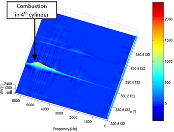
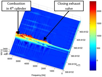
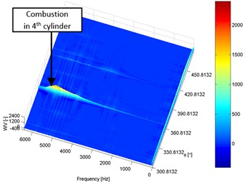
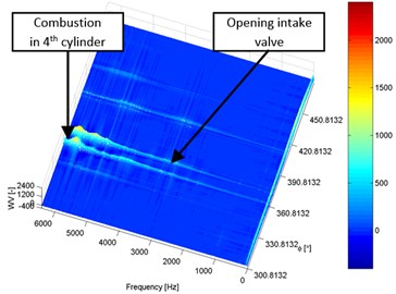
Fig. 5Wigner-Ville’a distributions of engine vibration signal with nominal valve clearances and with increased clearance of the exhaust and intake valve, rotational speed ~873rpm: a), c), e), g) Engine in good condition, b), d), f), h) Engine with increased valve clearances
a)
b)
c)
d)
e)
f)
g)
h)
If the valve timing angles are close to or coincide with the local increase of the vibration amplitude caused by the combustion process, a significant increase of the vibration amplitude caused by excessive valve clearance is observed. Also, the vibration frequency range in which there is the increase in the amplitude, is similar in this case to that at which the combustion process occurs.
If the valve timing angles of valves with an increased clearance are far away from the local increase in signal amplitude caused by the combustion process, the situation is different. During the tests it was observed that in this case, the vibration amplitude change caused by valve clearance had a much smaller value and occurred in the lower frequency range.
Four-stroke internal combustion engines are characterised by local instantaneous change of rotational speed caused by the implementation of individual power strokes [38, 39]. The study compared changes in engine’s rotational speed in subsequent working cycles, in cases of nominal and increased valve clearance. The results of average engine speed in subsequent 70 working cycles presented in Fig. 6 showed a small effect of increased valve clearance on uneven rotational speed of the engine.
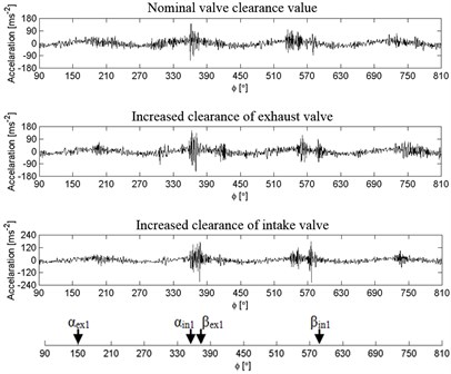
Fig. 6Vibration waveform of an engine with nominal clearance, and with an increased clearance of the exhaust and intake valve, rotational speed ~873 rpm
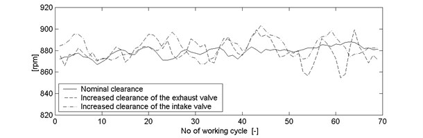
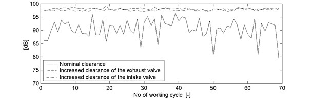
Fig. 7Vibration a) and noise b) waveform of an engine with nominal clearance, and with an increased clearance of the exhaust and intake valve, rotational speed ~873 rpm
a)
b)
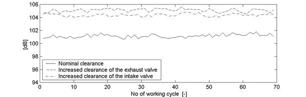
The study also included an analysis of the impact of changes in engine condition on the overall level of vibration and noise in subsequent cycles of its operation.
The average level of vibration and noise of an SI engine for each full cycle of its operation during work at constant rotational speed was calculated using the Eq. (2) and (3) [40]:
where: – the vibration acceleration signal, – the acoustic pressure signal, – reference acceleration, – reference acoustic pressure, – the length of analysis range, – the beginning of the analysis range, – the number of the analysis range.
The results of these calculations presented in Fig. 7 showed an increase in the vibration level by about 4 dB and engine noise level by about 6 dB due to the presence of increased valve clearance. It can therefore be concluded that a small change in the technical condition at idle speed of an engine causes a significant increase in the level of vibration and noise.
3.2. Tests with variable rotational speed of an engine
Combustion engines are devices whose level of vibration and noise depends, among other things, on the instantaneous rotational speed, load and technical condition [13, 25, 27, 31, 35-37]. The following part of the paper presents the calculation of the impact of changes in the rotational speed and the technical condition on the level of engine vibration and noise.
Eq. (2) and (3) were used to calculate the average level of vibration and noise of an SI internal combustion engine during acceleration for each full cycle of operation. Vibratory signals of the engine in good condition and with increased clearances were analysed. The results of these calculations are included in Fig. 8.
Fig. 8Change in the level of vibration and noise of an SI engine in different condition during acceleration
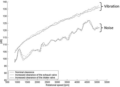
The calculation results indicate that the level of engine vibration varies by as much as 30 dB in the range from idle speed to the maximum speed recorded in the tests (approximately 5000 rpm). The observed vibration change waveform in this case is nearly linear, and local increase in vibration is not observed. Spread of the recorded vibration values was within 3 dB.
The calculations of the registered instantaneous acoustic pressure level at a distance of 0.5 m from the valve cover showed a lower noise level from the level of recorded vibration by about 8-15 dB. These values depend on the instantaneous engine speed. The noise registered shows a tendency for a general increase of its level along with the increase of speed up to about 25 dB, but this increase is not linear and shows local maxima.
Based on the results of these analyses it can also be concluded that during the acceleration of the engine, slight increase in the value of the engine valve clearance did not cause differences in the overall level of engine vibration and noise compared to its condition with nominal values of valve clearances.
Further tests compared the time signals of vibration acceleration during the acceleration the engine at varying rotational speeds, respectively, amounting to approximately: 873 rpm, 1550 rpm, 2040 rpm, 2520 rpm and 3000 rpm. These waveforms are presented in Fig. 4 and 9.
Fig. 9Waveforms of engine vibration with nominal valve clearance, with increased clearance of the exhaust and intake valve, at different rotational speeds: a) ~1550 rpm, b) ~2040 rpm, c) ~2520 rpm, d) ~3000 rpm
a)
b)
c)
d)
These tests showed that significant local changes in the vibration amplitude occur along with the increase of engine’s rotational speed. Comparing these changes to those occurring at idle speed, it can be concluded that they change their value during engine acceleration and at the same time there are new local changes in the vibration amplitude.
Increasing rotational speed above idle speed also caused a change in the local symptoms of an increased valve clearance in the vibration signal. Symptoms with the smallest amplitude (at idle speed), at a higher speed, have a very low amplitude or may disappear. In the case of the symptoms that occur in the area of amplitude change caused by the combustion process, signal modulation is also observed.
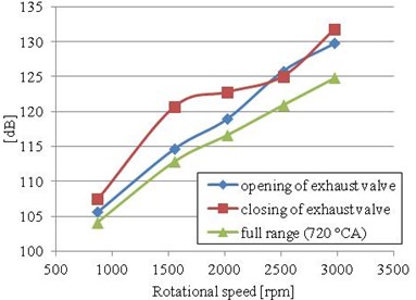
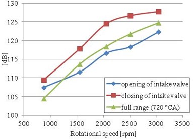
In order to accurately determine the effect of rotational speed on the vibration signal emitted, the average vibration level was analysed in the full range of operating conditions of the engine (720°) and in the ranges of valve timing angles corresponding to the opening and closing of valves with increased clearances. Calculations of the measure of vibroactivity were performed according to the Eq. (2) and the results of calculations are presented in Fig. 10.
Fig. 10The measure of vibroactivity determined in the range of angles corresponding to the opening of valves with increased clearances and for the 720° CA, at various engine speeds during acceleration: a) Engine with an increased clearance of the exhaust valve, b) Engine with an increased clearance of the intake valve
a)
b)
In any case, it can be seen that the measure of vibroactivity increases with increasing engine speed. The value of the measure in the valve timing range corresponding to the opening and closing of individual valves with an increased clearance calculated in this case has shown that a greater sensitivity of vibration measures to an increased clearance occurs in case of analysis of vibrations occurring during valve closing, and not opening.
4. Conclusions
Changes in the vibroactivity of combustion engines can be caused by various factors which include rotational speed, load, and technical condition. At the same time, the vibro-acoustic signal in modern internal combustion engines should be regarded as an important source of diagnostic information about their condition.
As part of the project, tests were carried out aimed to assess changes in the level of engine vibroactivity in stationary and non-stationary operating conditions, and additionally, in different technical conditions.
The study demonstrated that in stationary operating conditions, local amplitude increases occur in the recorded vibration signal cause by the combustion process in the selected cylinders, increased valve clearance, but also the lack of such change in the amplitude caused, for example, by misfire. The calculations of time-frequency distributions of vibration signals performed made it possible to determine that a local change of the engine vibroactivity caused by increased valve clearances strongly depends on the range of the crankshaft rotation angle in which the individual valves open and close (range of valve timing). It has been calculated that the increased valve clearance increases the average vibration level by about 4 dB, and the noise of an SI engine by about 6 dB.
The calculations performed in non-stationary conditions showed that the change in engine speed from idle to about 5000 rpm causes a vibration increase by about 30 dB, and noise near the engine by about 25 dB. These studies have also shown that along with the increase in engine speed, significant local changes in the vibration amplitude can be observed. It can be seen that changes of the vibration amplitude, which occurred at idle speed, change their value as the engine accelerates and at the same time the occurrence of new local amplitude changes can be observed. Local changes in the vibration level can therefore in this case hinder the diagnosis of the technical condition of the engine. The calculated value of the measure of vibroactivity showed that a better distinction of valves with an increased clearances is obtained during the analysis of vibrations occurring during valve closing than during opening.
Summarising the tests presented in the paper, it can be concluded that there is a significant impact of the combustion engine speed on the qualitative and quantitative changes that occur in the vibration signals and the noise registered. Assessing local vibroactivity changes in the engine operated in stationary and non-stationary conditions, as well as changes caused by increased valve clearances, it can be concluded that the diagnostic tests of an engine in regard to the detection of increased valve clearance should be carried out at a fixed idle speed.
References
-
Augustyńska D., Zawieski W. Protection against noise and vibration in the working environment. Central Institute for Labour Protection, Warsaw, 1999.
-
Engela Z. W., Sadowskiego J. Environmental protection against noise in Poland in the light of the provisions of the European. Central Institute for Labour Protection – National Research Institute, Warsaw, 2005.
-
Ross B. M., Wolde T. Noise from traffic as a worldwide policy problem. Noise Control Engineering Journal, Vol. 49, Issue 4, p. 159-161.
-
Salomons E. M., Berghauser Pont M. Urban traffic noise and the relation to urban density, form, and traffic elasticity. Landscape and Urban Planning, Vol. 108, Issue 1, p. 2-16.
-
Bartłomiejczyk M., Połom M. Exploitation and development of the infrastructure and rolling stock trolleybus transport company in Gdynia. Technique of Rail Transport, Vol. 7-8, 2010, p. 18-21.
-
Sadowski J. Basics of urban acoustics. Publishing House Arkady, Warsaw, 1982.
-
Bartłomiejczyk M., Połom M. The promotion of urban electric transport. Buses – Technique, Operation, Transport systems, Vol. 7-8, 2011, p. 42-45.
-
Makarewicz R., Kokowski P. Prediction of noise changes due to traffic speed control. Journal of the Acoustical Society of America, Vol. 122, Issue 4, p. 2074-2081.
-
Van Renterghem T., Botteldooren D., Hornikx M., Jean P., Defrance J., Smyrnova Y., Kang J. Road traffic noise reduction by vegetated low noise barriers in urban streets. Proceedings – European Conference on Noise Control, p. 944-948.
-
Lu M.-H., Jen M. U. Source identification and reduction of engine noise. Noise Control Engineering Journal, Vol. 58, Issue 3, p. 251-258.
-
Figlus T., Wilk A. Comparison of the sound pressure measurement and the speed measurement of the gearbox vibrating surface. Transport Problems, Vol. 7, Issue 1, 2012, p. 37-42.
-
Wilk A., Madej H., Figlus T. Analysis of the possibility to reduce vibroactivity of the gearbox housing. Maintenance and Reliability, Vol. 50, Issue 2, 2011, p. 42-49.
-
Burdzik R. Research on the influence of engine rotational speed to the vibration penetration into the driver via feet – multidimensional analysis. Journal of Vibroengineering, Vol. 15, Issue 4, 2013, p. 2114-23.
-
Wei H., Li Z., Liang X., Shu G. Influence of the accelerating operation mechanism on the combustion noise in DI-diesel engines. International Journal of Automotive Technology, Vol. 13, Issue 3, 2012, p. 373-388.
-
Burdzik R., Konieczny Ł., Figlus T. Concept of on-board comfort vibration monitoring system for vehicles. Activities of transport telematics, 13th International Conference on Transport Systems Telematics, Poland, 2013.
-
Burdzik R., Konieczny Ł. Application of vibroacoustic methods for monitoring and control of comfort and safety of passenger cars. Diffusion and Defect Data Pt.B: Solid State Phenomena, Vol. 210, 2014, p. 20-25.
-
Steffens C., Korfer T., Hanses G., Rosplesch A., Kremer F., Schaub J. Improvement of comfort aspects for high efficiency diesel engines. SAE Technical Papers, 2013, p. 5.
-
Luft T., Ringwelski S., Gabbert U., Henze W., Tschöke H. Noise reduction potential of an engine oil pan. Proceedings of the FISITA 2012 World Automotive Congress, Vol. 201, 2013, p. 291-304.
-
Liu H., Zhang J., Bi F., Shi Y., Ma W. Radiation noise prediction and low-noise modification of diesel engine. Chinese Society for Internal Combustion Engines, Vol. 29, Issue 3, 2011, p. 265-9.
-
Frenne N, Johansson O. Acoustic time histories from vibrating surfaces of a diesel engine. Applied Acoustics, Vol. 67, Issue 3, 2006, p. 230-248.
-
Paslawski J. Highway noise management using advisory system. International Journal of Environment and Pollution, Vol. 35, Issue 2-4, 2008, p. 275-295.
-
Sandberg U. Tyre/road noise – myths and realities. The International Congress and Exhibition on Noise Control Engineering the Hague, The Netherlands, 2001.
-
AlbarbarA., Gu F., Ball A. D. Diesel engine fuel injection monitoring using acoustic measurements and independent component analysis. Journal of the International Measurement Confederation, Vol. 43, Issue 10, 2010, p. 1376-1386.
-
Albarbar A., Gu F., Ball A. D., Starr A. Acoustic monitoring of engine fuel injection based on adaptive filtering techniques. Applied Acoustics, Vol. 71, Issue 12, 2010, p. 1132-1141.
-
Albarbar A., Ball A., Starr A. On acoustic measurement based internal combustion engines condition monitoring. Non-Destructive Testing and Condition Monitoring, Vol. 50, Issue 1, 2008, p. 30-34.
-
Pruvost L., Leclère Q., Parizet E. Diesel engine combustion and mechanical noise separation using an improved spectrofilter. Mechanical Systems and Signal Processing, Vol. 23, Issue 7, 2009, p. 2072-2087.
-
Madej H., Flekiewicz M., Wojnar G. Application of continuous wavelet transform (CWT) for vibration analysis of internal combustion engines. Nauk.-Probl. Mot. PAN, 2008, p. 259-268.
-
Chiatti G., Chiavola O., Recco E. Combustion and vibration characteristics in a small displacement diesel engine fueled with biodiesel blends. SAE Technical Papers, 2013, p. 4.
-
Zheng G. Piston slap reduction considering coupled vibration of an internal combustion engine. Journal of Vibration and Shock, Vol. 32, Issue 11, 2013, p. 167-72.
-
Dziurdź J. Application of correlation and coherence functions in diagnostic systems. Diffusion and Defect Data Pt. B: Solid State Phenomena, 2013, p. 3-12.
-
Madej H., Czech P. Discrete wavelet transform and probabilistic neural network in IC engine fault diagnosis. Maintenance and Reliability, Vol. 4, 2010, p. 47-54.
-
Wang L., Li D., Yang Z. Fault diagnosis of hydrogen-fueled engine using lifting wavelet packet transform. International Review on Computers and Software, Vol. 7, Issue 2, 2012, p. 862-868.
-
Czech P., Madej H. Application of cepstrum and spectrum histograms of vibration engine body for setting up the clearance model of the piston-cylinder assembly for RBF neural classifier. Maintenance and Reliability, Vol. 4, 2011, p. 15-20.
-
Yang C., Feng T. Abnormal noise diagnosis of internal combustion engine using wavelet spatial correlation filter and symmetrized dot pattern. Applied Mechanics and Materials, Vol. 141, Issue 1, 2012, p. 168-73.
-
Figlus T., Wilk A., Franke P. The estimation of changes in the noise level generated by devices equipped with two-stroke internal combustion engines with small displacement volume. FME Transactions, Vol. 41, Issue 3, 2013, p. 216-221.
-
Figlus T., Wilk A. The influence of drive parameters and technical condition on the vibroactivity of devices with single-cylinder internal combustion engines. Transport Problems, Vol. 8, Issue 1, 2013, p. 79-85.
-
Shatnawi Y., Al-Khassaweneh M. fault diagnosis in internal combustion engines using extension neural network. IEEE Transactions on Industrial Electronics, Vol. 61, Issue 3, 2014, p. 1434-1443.
-
Wajand J. A., Wajand J. T. Internal combustion engine. WN-T, Warsaw, 1993.
-
Droździel P. The new classification of start-up phases of the diesel engine. Scientific Problems of Machines Operation and Maintenance, Vol. 4, Issue 144, 2005, p. 87-96.
-
Müller L. Transmissions design. WN-T, Warsaw, 1996.
About this article

