Abstract
Taking images for airborne photogrammetry, tilt angles (drifts) variations of camera are resulting to objects positions on the images therefore influence to correctness and accuracy of produced geodata. Several experiments have been done for investigation of camera’s roll-pitch-yaw angles determination regarding to technical flying means orientation in the space. Using aerial triangulation technique, exterior orientation parameters of each image from entire flight strip – projection center coordinates and image tilt angles with estimated accuracy are presented. Results show coincidences or discrepancies to requirements specified in aerial photography regulations. In order to investigate deflections of camera’s tilts, stereo pair of images has been processed using airborne photogrammetric approach and different software. Two digital photogrammetric software (DDPS and LISA PHOTO) used in experimental image orientation operates on particular algorithms. Determined values of exterior orientation parameters differ not significantly. Exterior orientation of images gained by Unmanned Aerial Vehicle (UAV) with mounted CCD camera has been done. As shows analysis, images from UAV Photogrammetry are under marketable tilts. Using a certain number of Ground Control Points (GCP) measured by GPS, exterior orientation was not possible; the results not meet the accuracy requirements.
1. Introduction
Different technical means are used for taking images in airborne photogrammetry. The high resolution camera mounted in aircraft generates imagery of area. The camera mount that requires primary – is to ensure vibration-free taking photography. There are a wide variety of camera mounts, e.g. one of such means is gyro-stabilized suspension mount. Many basic photogrammetric procedures involve the use of vertical aerial photographs. An aerial photograph is considered truly vertical when the optical axis of the camera is in perfect alignment with the plumb line. Because of unavoidable angular tilts of the aircraft during the exposure, virtually all aerial photographs are tilted to some degrees for the perfect aerial camera stabilizer has introduced. Tilt is the effect of lateral tip of the wings of the aircraft or the dipping of the aircraft fore and aft. The tilt of the axis of the camera at the moment of exposure causes marked displacement of images on the photograph. However, images under significant tilt can have potentials for use in some special cases. Oblique images capture the scene under a tilt angle: oblique cameras lie between 30° and 45°. The tilt – the angle between nadir and optical axis improves visibility of vertical structures, but raises the occlusions: self-occlusion (e.g. when side of building becomes invisible) and occlusions by other objects. Occlusions can be avoided or its effect reduced by increasing the number of images taken from different viewpoints and by increasing overlap. Oblique aerial views of urban areas significantly easy the creation of 3D city models [1, 2].
With today’s operational unmanned aerial systems, photogrammetry has started a new era. Remotely controlled unmanned airborne vehicles (UAV) with integrated sensor are increasingly finding a place in the photogrammetric application. Main features of UAV Photogrammetry are considered with respect on costs (low-cost), flying altitude (low-high), capability of image acquisition in real-time that’s quality depends on sensors features, flight performance, influence of atmospheric and environment conditions, wind influence, etc. [3-5]. However, not every UAV is suited for aerial mapping. Vibration can be a major problem in small UAVs and can come from a variety of sources, but in UAVs the most significant source is rotating equipment (e.g. unbalanced propeller, etc.). The ability to fly at low altitude – is essential priority getting high resolution images [6, 7]. The UAV are light, because of that there can be integrated ease (amateur) cameras, and so the image resolution and quality may not always meet the needs of the user. The interest of UAV great potential for digital photogrammetry application is rising in many countries, as well as in Lithuania.
Using airborne photogrammetry for area mapping, digital surface modelling requires such data: images, GPS coordinates, camera parameters. Image orientation requires these optional data: roll-pitch-yaw or omega-phi-kappa angles and ground control points, to improve accuracy [8, 9]. Tilt angles variations of technical flying means (as well as camera’s drifts) are resulting objects positions on the images correctness and accuracy of produced geodata. Therefore, the goal of analysis is to investigate drifts values using different approaches and means for determination of image exterior orientation parameters and verifying of coincidence to requirements (specifications).
2. Methodology of interior orientation parameters determination
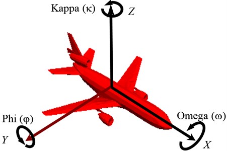
Reconstruction of the orientation of each image means definition the exact position of all images (photos) in the terrain coordinate system. The goal is to get the six parameters of the exterior orientation , , , , , . In a case of aerial photogrammetry, the values of phi () and omega () normally should be near zero. But in practice, this will never happened due to wind drift and small movements of the aircraft. The value of kappa () is defined according to -axis of counting anti-clockwise (Fig. 1). Non zero values of phi () and omega () as well as terrain relief leads to scale variation within photos.
Fig. 1Aircraft tilt angles: roll (κ), pith (φ), yaw (ω)
Exterior orientation calculates relation between image and object coordinates system. For this task ground control points (GCP) – the points which is represented in the image ant three-dimensional terrain coordinates (, , ) are known from geodetic measurements.
The images orientation can be complete in two different ways. First – process involves three steps: interior-relative-absolute orientation. Within the relative orientation the two images are connected by the calculation of model coordinates. Then, these are transformed to terrain coordinates in the absolute orientation. Second – for each image independently measuring control points carry out the exterior orientation.
The relative orientation of the images gives three-dimensional information, but the model is without scale, the origin of the axes is not determined and the axes system is not oriented to the ground system. To have these elements, absolute orientation must be done. The purpose of absolute orientation is the transformation from model coordinates to ground coordinates. The relation between the models coordinates , , and the ground coordinates , , is expressed by the equations [10, 11]:
where , , – ground coordinates of the perspective centre, – scale factor, – matrix of the spatial rotation of the system into the system:
A minimum of seven equations is required for the determination of the seven parameters , , , , and . Therefore sufficient number of control points must be available. Control point (, , are known) gives three equations – planimetric control point (, are known) gives two equations and a height control point ( known) gives one equation. The unknowns are determined by a least squares adjustment, with the first approximation values:
When these parameters are known, the ground coordinates of every point tracked down on the two images can be computed.
Different software applies different algorithms for image processing. Two digital photogrammetric systems used in experimental image orientation operate by different ways.
3. Experimental procedures of camera drifts evaluation
Several experiments have been done for investigation of tilt angles variations (camera’s drifts) regarding to technical flying means orientation in the space. A flight (navigation) and taking aerial photographs have to be done concerning to specifications that’s outlines the specific requirements such as flying height, overlaps, swing round (yaw) tolerances, etc.
Aerial images at a scale of 1:6000 with 62 % forward and 33 % sideward overlap covering the eastern-northern part of Vilnius were used for experimental photogrammetric measurements. Digital images are of size of 16862×16861 pixels. Aerial cameras RMK TOP calibration parameters and control points were used for interior and exterior orientation. Camera’s focal length 153.6 mm, flying height 910 m. Coordinates of ground control points were determined by GPS method.
3.1. Aerial triangulation
Photogrammetric technique was used for creation of dense control point’s network and determination of 3D coordinates. The model of mathematics block network adjustment has been based on collinearity equations. Equations of aircraft GPS antenna coordinate corrections are involved into process of adjustment. Results from aerial triangulation are parameters of exterior orientation (projection center coordinates of each image and tilt angles) with estimated accuracy [12]. One entire strip with 24 images (numbered from 215 to 238) has been selected as test model for drifts investigation. Fragment of determined exterior orientation parameters is presented in Table 1. Fig. 2 shows graphical representation of tilt angles variations of images from selected test model.
Table 1Fragment of exterior orientation parameters with estimated standard deviation (m/gon)
Images No. | ||||||
215 | 6066445.305 0.133 | 592875.211 0.105 | 1065.741 0.132 | 0.1572 0.0066 | 0.9945 0.0079 | 199.4832 0.0046 |
216 | 6066450.859 0.119 | 592343.814 0.087 | 1065.698 0.113 | 0.1901 0.0050 | 1.2260 0.0072 | 198.9848 0.0028 |
….. | ….. | ….. | ….. | ….. | ….. | ….. |
227 | 6066463.483 0.087 | 586559.113 0.067 | 1066.558 0.063 | -0.0067 0.0040 | 1.1195 0.0053 | 200.4561 0.0017 |
228 | 6066461.755 0.090 | 586017.042 0.069 | 1066.017 0.062 | -0.3055 0.0039 | 0.9752 0.0055 | 200.3307 0.0017 |
229 | 6066462.314 0.093 | 585483.446 0.069 | 1066.687 0.063 | -0.1626 0.0038 | 1.8138 0.0056 | 200.1176 0.0017 |
Fig. 2Entire strip image’s tilt angles variations (in gons): a) pith (φ); b) yaw (ω); c) roll (κ)
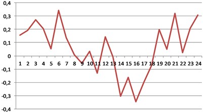
a)
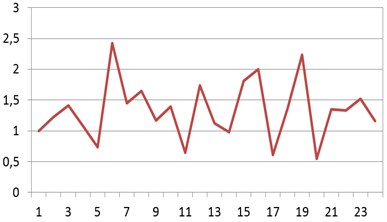
b)
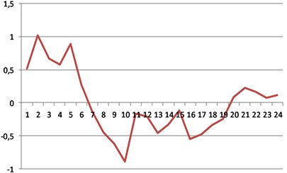
c)
Regarding to photogrammetric mission specifications flight line deviation from straight path shall not exceed 2 % of the flight path length, tilt and drift of aerial photographs should not exceed ±2° and roll – up to ±5° when measured between the base line and the line parallel to the frame of the photograph. Maximal values of tilt angles can get not more than 2 % of aerial photographs and drift – shall not exceed 5 %. Departures from flight heights to produce the recommended aerial photographs scale should not exceed 3 % [13, 14].
In the test model maximal deflection angles (tilt, drift and roll) are: –0.3473 gon (–0.3126°), 2.2336 gon (2.0103°), 1.0152 gon (0.9137°).
3.2. Photogrammetric images processing
In order to investigate deflections of camera tilts stereo pair (numbered by 229/228) of images have been selected for image processing using airborne photogrammetric technique and different software. Digital photogrammetric software used in experimental image orientation operates by different algorithms.
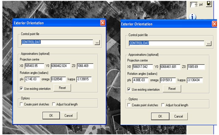
Digital Photogrammetric Workstation LISA has been applied for determining of images exterior orientation parameters. Digital photogrammetric software LISA with extensions of LISA FOTO and raster GIS software LISA BASIC developed at the Hannover University, Germany has a lot of possibilities in image processing [15]. Exterior orientation using LISA FOTO was carried out independently for each image. Fig. 3 presents images exterior orientation results.
Fig. 3Images exterior orientation parameters in LISA software application
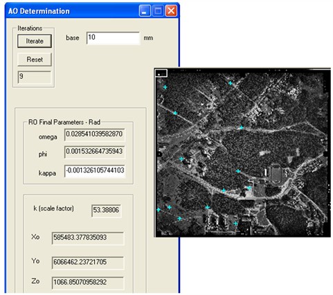
Using workflow of photogrammetric digital images processing realized on a Digital Photogrammetric System (DDPS) exterior orientation parameters of images have been defined (Fig. 4). The software DDPS was developed within the cooperative project between Universities of Liege, Belgium and the Institute of Geodesy and Cartography, Poland. DDPS is complete and integrated photogrammetric package with user-friendly interface [16].
Fig. 4Image (left) exterior orientation parameters in DDPS software application
Camera orientation in space comparison analysis results obtained from different softcopies application is summarized in Table 2.
Table 2Comparison results of images exterior orientation parameters (m/deg)
Images No. | ||||||
Aerial triangulation | ||||||
228 | 6066461.755 | 586017.042 | 1066.017 | –0.2749 | 0.8778 | –0.3157 |
229 | 6066462.314 | 585483.446 | 1066.687 | –0.1463 | 1.6324 | –0.1060 |
LISA | ||||||
228 | 6066461.681 | 586017.042 | 1065.690 | –0.2796 | 0.8602 | –0.2955 |
229 | 6066462.024 | 585483.95 | 1066.469 | –0.1226 | 1.6357 | –0.1018 |
DDPS | ||||||
228 | 6066461.181 | 586017.129 | 1065.928 | –0.0504 | 0.9013 | –0.2034 |
229 | 6066462.237 | 585483.378 | 1066.851 | –0.0878 | 1.6353 | –0.0760 |
As seen from Table 2, parameters of camera orientation in space, determined by different photogrammetric technique, varies not significantly. Regarding to aerial triangulation maximal difference is of pith angle (), when using DDPS softcopy – 0, 2245°.
3.3. UAV Photogrammetry
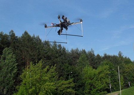
Next step of investigation was determining exterior orientation parameters when processing UAV images. The built-up area was selected as experimental test. The images were taken by self-constructed UAV remotely operated and with integrated digital camera Sony NEX-5 (see Fig. 5). Some characteristics of used digital camera: resolution – 14 mega pixels (4592×3056), focal length 16 mm, image’s pixel size 72.6 µm. UAV flying height above ground was about 30 m.
Fig. 5UAV used for Photogrammetry
Several UAV images have been selected for image photogrammetric processing using software LISA FOTO.
Examples of determined parameters of exterior orientation are presented in Fig. 6.
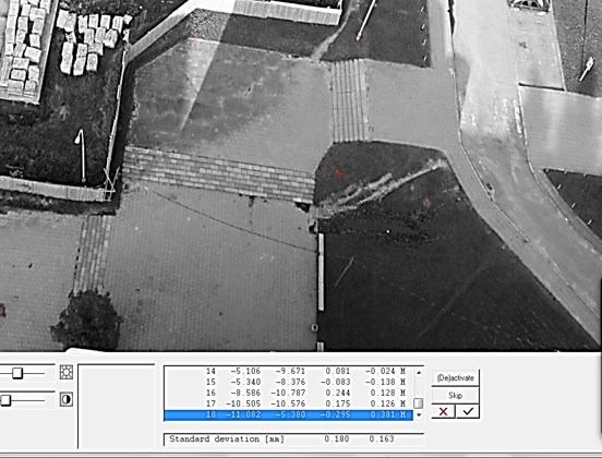
Image processing results shows significant values of tilt angles, e.g. 10.9656°,60.2262°, 8.6811°. When processing such very deflected UAV images, impossible to perform exterior orientation in required accuracy. Example of selected UAV image orientation exterior orientation results are presented in Fig. 7.
The residuals in and at every point as well as the resulting standard deviation are given referring to the image. Required accuracy of imagery interior orientation should be reached up to half of an image pixel. Processed images resolution is 72.6 µm. As seen from Fig. 7 residuals are not about half a pixel – 0.036 mm.
Fig. 6UAV images exterior orientation parameters
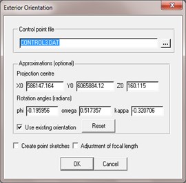
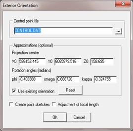
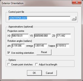
Fig. 7Results from UAV image exterior orientation
4. Conclusions
Airborne photogrammetry produces images with drift variations. The tilt of the axis of the camera at the moment of exposure causes marked displacement on the photograph. Tilt is the effect of lateral tip of the wings of the aircraft or the dipping of the aircraft fore and aft. A photograph is considered tilted when the angle between the perpendicular projection through the center of the lens and the plumb line is greater than 3°.
For getting very high quality of aerial photographs at a flight mission for territory’s photogrammetric mapping, the developed requirements should be considered. After analysis of determined exterior orientation parameters (projection center coordinates and image roll-pitch-yaw) of each image from entire flight strip with help of aerial triangulation technique, have been detected not significant deflection regarding to requirements specified in aerial photography regulations. As was determined, maximal image tilt has yaw angle: 2.0103°. It was approved that tilt and drift of aerial photographs nearly not exceed ±2° as required in specifications.
Using different photogrammetric software DDPS and LISA PHOTO, determined values of images exterior orientation parameters differ not significantly.
The application of Unmanned Aerial Vehicle (UAV) with embedded CCD camera, getting images from bird fly is rapidly growing and usefulness for land surface mapping should be investigated. UAV images are under significant oblique as shows investigations. Using a certain number of Ground Control Points (GCP) measured by GPS, exterior orientation was not possible – the results not meet the accuracy requirements. Therefore, traditional photogrammetric software is undesirable for UAV Photogrammetry and needs special designed algorithm involved in images processing softcopy.
References
-
Wolf R., Dewitt A. Elements of Photogrammetry with Application in GIS. 3rd edition, USA McGraw-Hill, 2000.
-
Konecny G. Geoinformation: Remote Sensing, Photogrammetry and Geographical Information Systems. London and New York, Taylor and Francis, 2003.
-
UAV Systems-Unmanned Aerial Photography. http://www.uavsystems.com.au/.
-
Eisenbeiss H. UAV photogrammetry. ETH Zurich, Switzerland, Mitteilungen, 2009.
-
Haala N., Cramer M., Weimer F., Trittler M. Performance test on UAV-based photogrammetric data collection. International Archives of the Photogrammetry, Remote Sensing and Spatial Information Sciences, Vol. 38-1/C22, 2011, p. 1-6.
-
Veprik A. Vibration protection of critical components of electronic equipment in harsh environmental conditions. Journal of Sound and Vibration, Vol. 259, Issue 1, 2003, p. 161-175.
-
Plasencia G., Rodríguez M., Rivera S., López Á. Modelling and analysis of vibrations in a UAV helicopter with a vision system. International Journal of Advanced Robotic System, Vol. 9, 2012, p. 1-9.
-
Nurminen K., Karjalainen M., Yu X., Hyyppä J., Honkavaara E. Performance of dense digital surface models based on image matching in the estimation of plot-level forest variables. ISPRS Journal of Photogrammetry and Remote Sensing, Vol. 83, 2013, p. 10-115.
-
Rock G., Ries J., Udelhoven T. Sensitivity analysis of UAV-photogrammetry for creating digital elevation models (DEM). International Archives of the Photogrammetry, Remote Sensing and Spatial Information Sciences, Vol. 38-1/C22, 2011, p. 69-73.
-
Manual of Photogrammetry. Edited by Chris McGlone, Fifth Edition, American Society for Photogrammetry and Remote Sensing, USA, 2004.
-
Ruzgienė B. Photogrammetry. Vilnius, Technika, 2008, (in Lithuanian).
-
Ruzgienė B., Žalnierukas A. Aerial triangulation using results from kinematic GPS method. Geodesy and Cartography. Vol. 24, Issue 1, 1998, p. 16-25, (in Lithuanian).
-
Ruzgienė B. Requirements for aerial photography. Geodesy and Cartography. Vol. 30, Issue 3, 2004, p. 75-79.
-
Ruzgienė B., Kaczynski R. Photographic mission specification for mapping urban territories at a large scale. The 6thInternational Conference Environmental Engineering, Vol. 2, 2005, p. 993-1005.
-
Linder W. Digital Photogrammetry. A practical Course. Springer-Verlag, Berlin, Heidelberg, 2009.
-
Donnay J. P., Kaczynski R. Didactic and digital photogrammetric software (DDPS). University of Liege, Belgium; Institute of Geodesy and Cartography, Warszawa, Poland, 2005.
About this article

The co-operation with Eglė Tamašauskaitė from master student at Geodesy and Cadastre Department and Evaldas Černiauskas from Aviation Institute, VGTU is highly appreciated.
