Abstract
Recently, the aircrafts tend to be replaced by unmanned, light, simple, aerial vehicles (UAVs), same can be said about the field of aerial photogrammetry. UAV system besides the standard airframe and engine includes main processor board, Inertial Navigation System (INS), Global Positions Systems (GPS), telemetry module. For areal imaging purposes there can be a photo camera mounted too. The images taken by the areal camera can later be processed by software which is specialized for photogrammetry. The project of testing Pix4d Mapper (Switzerland) and PhotoMod (Russia) software programs is described in this paper. Pix4d Mapper is software specialized for UAV images proceedings meanwhile PhotoMod is designed for common photogrammetry proceedings. PhotoMod request some special photogrammetric knowledge from the user. There were 36 images processed producing ortho-mosaic and surface model. The results are further described in the paper.
1. Introduction
The mapping of terrain is a long lasting process that could last from half a year up to several years. Recently designed technology constructed by the scientists and engineers of Space Science and Technology Institute (SSTI) together with the students of A. Gustaitis Aviation Institute (AGAI) would assist in updating that process. For the purposes of minor terrain mapping like cases of maps updating, military purposes, studies of nature and for the other intentions it is recommended to deploy the constructed UAVs.
The UAVs are available in various sizes, shapes and structures; they signify themselves by the manifold characteristics [1]. Previously, those were ordinary model aircrafts under remote control, but recently, there is a tendency to use the autonomous unmanned aerial vehicles, which move according to the pre-programmed flight pathway or they could be operated by the help of a more complicated system of dynamic automation. For areal imaging purposes a digital, calibrated and integrated camera is present in an UAV, which is to acquire the Earth’s surface photographic images. The images made during the UAV flights can later be processed by applying the methods of photogrammetry, with substantially lower costs than they used to be in cases, when the images were taken from an airplane with the complicated and rather expensive equipment, devices and facilities [1-4].
SSTI and students of AGAI designed two UAV systems for aerial photography. One of the systems was used in four test flight projects. During the flights by UAV made lot of images. The images were processed by different software: Pix4d Mapper and PhotoMod. These experimental projects explain basics of images processing and shows the advantages and disadvantages and difference between used software’s.
2. Platform of UAV System
An unmanned aerial vehicle, commonly known as drone is an aircraft without a human pilot onboard. Its flight is controlled either autonomously by onboard computers or by the remote control of a pilot on the ground or in another vehicle. The tested UAV is an electric powered flying wing that is flown autonomously through its own onboard autopilot system. An Inertial Measurement Unit (IMU) provides stabilization for the aircraft. GPS (Global Position System) navigation is used to guide the aircraft to its destination. The UAV is landed autonomously by parachute via point and click on the included Ground Control Software or performing belly landing. The main performances are show in Table 1.
Table 1Flying wing X-5 and 1.8 m RC performance
UAV | X-5 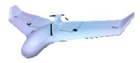 | 1.8 m plane 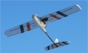 |
Length | 0.5 m | 1,5 m |
Wingspan | 1 m | 1.8 m |
Gross weight | 2 kg | 5 kg |
Payload | 0.5-0.7 kg | 0.5-0.7 kg |
Max speed | 80 km/h | 70 km/h |
Cruising speed | 55 km/h | 50 km/h |
Flight time | 30-45 min. | 30-45 min. |
Range | 30-50 km | 20-40 km |
Engine | Electrical | Electrical |
Control | Fully automatic | Fully automatic |
Take off | Hand launch | Hand launch |
Landing | Parachute | Belly landing |
Telemetry of control | 430 MHz direct control about 15 km | 430 MHz direct control about 15 km |
People require in service | 1 | 1 |
Camera | Canon S100 | Canon S100 |
The planes performances are very similar. One of them is flying wing type and second one – conventional. Due to the airframe type (flying wing) X-5 is faster, smaller. Both of them are made of foam and control systems are the same. It is Arduino-based ArduPilot. Ground unit consists of a computer with special software and telemetry module.
The UAV had an installed digital camera Canon S100 intended for test flights. X-5 has the camera mounted in the fuselage, with automatic lens coverage and 1.8 m plane has photo camera hang up under the wing. The camera lens optics was calibrated by the special German program Tcc according to the calibration test field – cube and the mode self-calibration processes by Pix4d Mapper software (see an article Chapter 4) [5, 6]. Flight over four tested objects was made by 1.8 m plane.
3. Data of UAV test flights
The test flights were performed on four areas located near Vilnius city (villages Kazbiejai and Melagenai) also at Taurage and Klaipeda (Lithuania). The selected objects areas, flight data, time and height, processing images number are shown in the Table 2.
The first two selected areas comprise buildings, roads, cultivated fields and natural vegetation. Next two test flights were made at urban city area and had multi-storey buildings. The flight height was 200-350 m. Consequently, there are 1:5000 scale images.
4. Photogrammetric software for images processing
The images were processed by two photogrammetric software Pix4d Mapper (Switzerland) and PhotoMod (Russia). The results are further described.
Table 2Information about tested flights
Object | Area, km2 | Flight data and time | Flight height, m | Number of processing images by Pix4d Mapper | Number of processing images by PhotoMod |
Village Kazbiejai | 0.11 | 2013-11-29, 10 a.m. | 200 | 36 | 20 |
Village Melagenai | 0.83 | 2012-12-12, 1 p.m. | 350 | 173 | 18 |
City Taurage | 0.79 | 2012-03-10, 3 p.m. | 220 | 214 | 10 |
City Klaipeda | 0.65 | 2012-10-19, 1 p.m. | 204 | 242 | – |
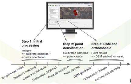
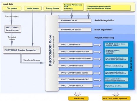
Pix4d Mapper has function, which automatically shows image center at Google Map. There is a need just upload images to Pix4d Mapper. Images center location by GPS provides information of working area. Useless images can be deleted. Selected images can be processing. The images processes are shown at Fig. 1. There are 3 main processing steps [7, 8].
Fig. 1Image processing by Pix4d Mapper
During initial processing (Step 1) digital photo camera is calibrated and images are orientated equally. Compact cameras are extremely sensitive to temperature differences, vibrations and shocks and these elements require a complete calibration for each flight. Pix4D software includes a powerful camera auto-calibration algorithm that takes the full information of each pixel of your images to estimate the optimal camera and lens calibration for each flight. This feature is critical to ensure perfect accuracy at any climate condition, without any manual and tedious user intervention involving checkerboard patterns that can be error prone steps. Pix4d Mapper software is initiate self-calibration, which calculate photo camera focal length , principal point location (, ) and radial, tangential distortions (, , , , ). Results of camera Canon S100 self-calibration parameters processing images of all test areas objects are in the Table 3.
The focal length is a property of the camera, its sensor and optic. It varies with temperature, shocks, altitude and time. The calibration process starts with parameters of an initial camera model and optimization of parameters with respect to the images. It is normal that the focal length is slightly different for each project. An initial camera model should be within 5 % of the optimized value to ensure a fast and robust optimization [9]. Test flight data (Table 3) shows that in the Taurage object focal length is different from other object. Probably the weather conditions made biggest impact on results. All the project results are valued and the mean lens focal length is calculated 5.732 mm (in this case).
Sometimes not all the images can be calibrated due to low key points at over covering area. There have to be more than 2000 joint key points for successful camera (images) calibration [10]. If there is forested area, there is a need to increase the frontal overlap area to 80-95 %. This must be done to increasing joint key points number.
There are results of key points and matching points number in the test flights (Table 4).
Table 3Internal camera Canon S100 parameters in the tested flight
Focal length, pix | Focal length, mm | Principal point, pix | Radial distortions | Tangential distortions | ||||
Village Kazbiejai | ||||||||
2906.347 | 5.406 | 1988.262 | 1463.751 | –0.047 | 0.012 | 0.004 | –0.003 | –0.001 |
Village Melagenai | ||||||||
2923.998 | 5.439 | 1973.220 | 1491.112 | –0.054 | 0.014 | 0.004 | –0.004 | 0.001 |
City Taurage | ||||||||
3577.760 | 6.655 | 2037.901 | 1492.670 | –0.049 | 0.002 | 0.007 | 0.000 | 0.003 |
City Klaipeda | ||||||||
2919.948 | 5.431 | 2013.602 | 1458.274 | –0.050 | 0.014 | 0.003 | –0.004 | 0.002 |
Table 4Result of the matching point number
Tested flights | Number of calibrated images | Number of median key points per images | Number of median matches point of calibrated images |
Village Kazbiejai | 36 | 37 442 | 15 361 |
Village Melagenai | 173 | 34 229 | 12 252 |
City Taurage | 204 | 15 716 | 6 619 |
City Klaipeda | 242 | 11 868 | 6 917 |
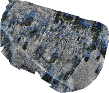
All the images of the villages Kazbiejai and Melagenai, and Klaipeda city have been calibrated. Calibrated images had from 6000 to 15 000 matching points. 10 images of Taurage city were not calibrated due to low matching point number. Ortho-mosaic preview shows not rendered (white places) orthophoto area (Fig. 2).
Fig. 2Preview ortho-mosaic before densification
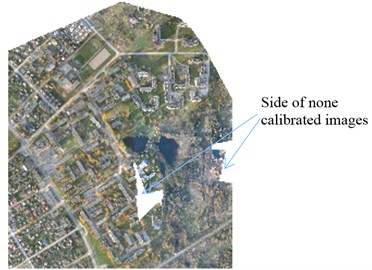
To correct this failure additional flight should be performed over the area and pictures with bigger longitudinal coverage taken.
Exterior image orientation. Exterior orientation in photogrammetry systems includes images interior and relative orientation. There are measured principal points during interior orientation process and these points location is determined during self-calibration (Table 3). In Pix4d Mapper all of these steps are operated automatically without user interference. The process of relative orientation is following [10]:
• Measuring of the tie points on stereo pairs in overlapping areas and triplet zones (if we have three images) manually or automatically;
• Input and measurement of ground control points (GCP). Majority of software recognize GCP points, but some software including PhotoMod cannot generate orthographic model without GCPs. Pix4d Mapper generates both of them. No GCP were entered. That means the geo-location of the project is done by averaging the position of the optimized geo-tags. GPS devices used for geo-tagging of original images may suffer from a global shift, leading to a global shift in the project of several meters.
The difference between the image geo tags (GPS) and the optimized camera positions in the test areas are showed in Table 5.
Table 5The difference between the image geo tags (GPS) and the optimized camera positions
Tested flights | Direction | ||
Longitude direction () | Latitude direction () | Altitude direction () | |
Geo tag localization variance sigma*, m | |||
Village Kazbiejai | 10.012 | 9.188 | 2.449 |
Village Melagenai | 15.647 | 1.746 | 1.432 |
City Taurage | 5.560 | 5.202 | 4.263 |
City Klaipeda | 3.609 | 2.224 | 1.929 |
*this does not correspond to the accuracy on the ground. | |||
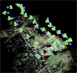
Data of Table 5 show that proceeding exterior image orientation without GCP key points gives accuracy 2-15 m of ortho-mosaic. In Fig. 3 the example of matching points and optimized camera position (green points) in village Kazbiejai are shown.
Fig. 3Identified matching point cloud and optimized camera position
When relative orientation is accomplished, triangulation process follows. Triangulation is a process when tie (matching points) points are transformed to geodetic coordinates system. All these photogrammetric work stages are performed automatically in the Pix4d Mapper software. There is no need to be familiar with basics of photogrammetry to do triangulation calculations.
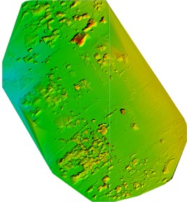
Next image processing step (2) is to determine point cloud densification which means filtering and smoothing of point clouds (Fig. 2). The generation of point cloud can lead to noisy and erroneous points. The noise filtering algorithm corrects the altitude of these points with the median altitude of the neighboring points. The noise filtering radius defines the size of the neighborhood to be considered. For a noisy point, only the points within the distance of radius will be used to correct this point. For example for a project with a 5 cm/pixel GSD (Ground Sampling Distance), a radius of 20 GSD units represents a distance of 1m. This means that points further than 1 meter of the noisy point will not influence its correction. The GSD is the distance between pixel centers measured on the ground in these test projects shown in the Table 6.
The bigger the value of image GSD is, the lower the spatial resolution of image is and less details are visible in the ortho-mosaic. The GSD is related to the flight height: the higher the altitude of the images, the bigger the GSD value. Even when flying at a constant height, the images of a same project cannot have the same GSD. This is due to the differences in elevation of the terrain and the inclinations of the camera while shooting. The final ortho-photo corrects this issue and is created using one unique GSD.
Table 6Results of ground sampling distance
Tested flights | GSD, cm |
Village Kazbiejai | 5.34 |
Village Melagenai | 6.54 |
City Taurage | 5.73 |
City Klaipeda | 6.76 |
Once the noise filter has been applied, a surface is generated from the point cloud. This surface can contain areas with erroneous small bumps. The surface smoothing algorithm corrects these areas by flattening them. It is important to understand that the surface smoothing deals both with the points and the surface generated from the points, whereas the noise filtering deals with points only.
DSM and ortho-mosaic generation contains five sections:
• Raster DSM: allows to select the output file format for the raster DSM;
• Grid DSM: allows to select the output file format for the vector DSM;
• Ortho-mosaic: allows to select the output file format for the ortho-mosaic as well as different options related to the ortho-mosaic generation;
• Triangle model: allows generate the Triangle Model while processing step 3. DSM and Ortho-mosaic Generation;
• Set as default options: option deactivated by default. When this option is deactivated the changes in one project will not apply to future projects. Clicking on this checkbox, options of this tab will be used as default options for future projects.
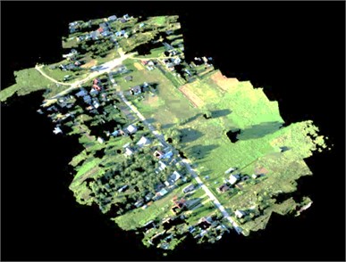
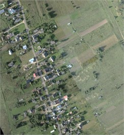
Fig. 4Elevation view and ortho-mosaic of village Kazbiejai project
Ortho-mosaic removes the perspective distortions from the images using the 3D model and then blends the ortho-rectified images together. A high number of matches/key points (more than 1000) is required to generate the 3D model. This method handles any type of terrains as well as large datasets. Geo-reference is well supported. Distances are preserved and therefore ortho-rectified images can be used for measurements purposes. Pix4D’s advanced algorithms allow the computation of a 3D point and elevation for up to every pixel of the original images. This feature enhances the accuracy of DSMs and provides true ortho-rectification to the mosaics.
Once the project has been processed, it is possible to use the results using the Mosaic Editor. The Mosaic Editor allows to (Figs. 4, 5):
• Visualize the DSM (raster GeoTIFF Digital Surface Model);
• Improve the visual aspect of the ortho-mosaic.
The ray Cloud Editor allows to:
• Visualize the different elements of the reconstruction: camera positions, point clouds, GCPs, automatic tie points, etc.
• Verify the accuracy of the reconstruction;
• Improve the visual aspect of the point cloud;
• Measure distances, surfaces and stockpiles.
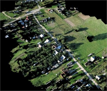
Fig. 5Ortho-mosaic of village Melagenai project
Improve the quality of ortho-mosaic in an easy and fast way. The Pix4d Mapper can remove moving objects by editing seam lines and selecting the most appropriate images. Seam lines and 3D views are shown in the Figs. 6, 7.
Fig. 6Seam line view
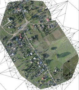
Fig. 73D view
Output result format is very important for next software to read the data [8, 10]. 2D and 3D output results easily readable by standard GIS (Geo TIFF, point cloud in LAS, LAZ, XYZ, PLY format), CAD and Photogrammetry software packages and Google tiles export in KML output format. Also object can be export in DXF, SHP and KML formats.
Pix4d Mapper software automatically generates an easy to use “5 Point Checklist” after initial processing that lets instantly assess the quality of the project. With just a quick glance, optimal results can be obtained by following the tips proposed in the “Help” feature of the report. The report displays scores of image, dataset, matching and geo-referencing quality, as well as an overview of the ortho-mosaic and DSM. It also provides detailed, quantitative measurements of the AAT, BBA and ground control points accuracy.
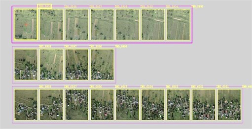
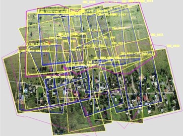
PhotoMod. To upload images to Google Maps a special function is needed. PhotoMod does not have such a function. Some other software like Digital Photo Professional has to be used. This software helped to select images of flight projects (Table 2). The images of village Kazbiejai project which were selected and processed with photogrammetric software PhotoMod are shown in Fig. 8.
Fig. 8Selected project images by PhotoMod
Majority photo-geometrical determinations have been done, in manual or semiautomatic mode, so user had to had good knowledge in photogrammetric basics. The images processing stages are shown in Fig. 9 [11].
Fig. 9PhotoMod image processing
Calibration parameters are entered to PhotoMod manually (photo camera have to be calibrated before) meanwhile Pix4d Mapper has the self-calibration system. Photo camera Canon S100 was calibrated in 2012 by the special TCC software (Germany) according to the calibration stand-cube [5, 6]. The test field – cube was photographed from different position: right, center and left. The focal length was fixed at the widest angle with the focus attached to infinite. The following distortions – parameters of the camera were determined: – the distance of the focal length; – the coefficient of the image scale; – the correction of the principle image point of the coordinate ; – the correction of the principal image point of the coordinate ; , – a camera lens radial – symmetric distortion; – a camera lens radial – asymmetric distortion. The obtained results are presented in Table 7.
Table 7Parameters of camera lens optics, camera Canon S100
Calibration parameters | Result in pixels | Accuracy of the results |
2.88232393E+003 | 1.98802050E+000 | |
, coefficient | 1.00047179E+000 | 5.83221020E-005 |
–1.63261043E+001 | 1.16958398E+000 | |
–1.87603888E+000 | 2.62542675E-001 | |
–5.16691758E-009 | 7.16637585E-011 | |
1.89104679E-016 | 1.32316596E-017 | |
–3.90038626E-007 | 3.60068319E-008 |
The accuracy of the camera calibration is characterized by the standardized deflection () of the weight unit, which indicates the accuracy of the identification and measurement of the points on the calibration stand. Theoretically, this value does not have to exceed 15 µm.
After calibration of camera Canon S100, the standard deflection of the weight unit was 3.16 µm; the acquired result is very good and acceptable. The size of the digital matrix of the image taken by the camera Canon S100 is 7.44×5.58 mm, thus, the smallest size of the image point (pixel) is 0.00186 mm. The distance of the focal length is 2882.323 pix (5.361 mm). A small distance of the focal length indicate, that the camera has a wide field of view, therefore, when taking images with this camera a large area of the location could be covered. A difference of focal length of photo camera Canon S100 was got from different softwares is 0.371 mm.
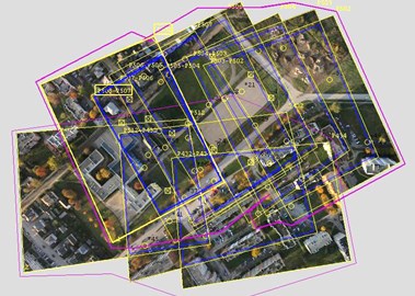
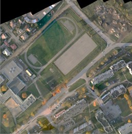
Proceeding images interior orientations PhotoMod manually measure principal points, which coordinates is half of all the photo matrix size (2000×1500 pix). Principal point location is corrected automatically for photo camera calibration parameters. Next Tie and GCP points are measured. Without GCP points PhotoMod cannot generate ortho-photo mosaic, though Pix4D can do it. Tie and GCP points at this test project were measured manually. There were 100 Tie and 11 GCP points. GCP points were selected at 1:5000 scale orthographical map (www.geoportal.lt). There was determining rectangular coordinates with 1-5 m accuracy. Ortho-photo mosaic should be more accurate if GCP coordinates be determined by geodetic method. Geometric model used in village Kazbiejai and city Taurage projects are show at Fig. 10.
Fig. 10Geometric model of village Kazbiejai object and city Taurage
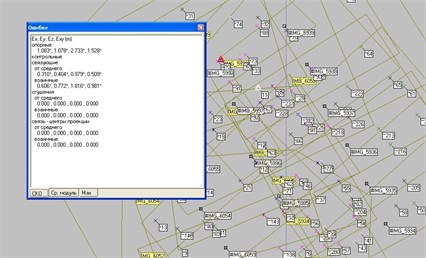
When relative orientation was made Tie point’s transformation to geodetic coordinate systems was started. Result of point transformation is shown in Fig. 11.
Fig. 11Result of point transformation
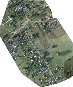
Root mean square of GCP points are 1.5 m and Tie points – 0.5 m. In case accuracy is sufficient and satisfies the requirements, it is possible to generate ortho-mosaic (Fig. 12.), surface model DTM and later according to this data render topographical map. These processes require some special modules with semi-automatic functions in PhotoMod.
Fig. 12Ortho-mosaic made by PhotoMod
a) Project of village Kazbiejai
b) Project of city Taurage
All output data can be exported to a selection of popular exchange formats. Ortho-mosaic may be saved into the following formats: BMP, DGN, ERDAS Img, GeoTIFF, JPEG, NITF, PCIDSK, PNG, TIFF. Result of comparison between two analyzed softwares was shown in the Table 8.
Table 8Comparison of software
Photogrammetric stages | PhotoMod | Pix4d Mapper |
Images deployment at world map | No | Automatically |
Photo camera calibration | No | Yes |
Images correction depending on photo cameras lens disorientations | Automatically | Automatically |
Image orientation: • interior orientation; • relative orientation; • triangulation. | Manually Semi automatically Automatically | Automatically |
Ortho-mosaic generation | Semi automatically by Mosaic module | Automatically |
Surface model (DTM) creation | Semi automatically by DTM module | Automatically |
Topographic map creation | Manually by Stereo Draw module | Manually |
5. Conclusions
The images acquired by UAVs are suitable for proceeding by different software packages: software like Pix4d Mapper special used for UAV image processing and PhotoMod photogrammetric software were analyzed in this paper.
The most important differences between software’s are the following:
1) Photo camera mounted on the UAV has to be calibrated. Camera implemented can be calibrated in laboratory conditions or images can be calibrated during processing. Pix4d Mapper software has some advantages, it has self-calibration and there is no need to worry about cameras parameters before taking images. PhotoMod software does not have such function, so photo camera parameters have to be known. These parameters have to be entered to the software first of all.
2) Images got from the UAV have GPS coordinates of image center. These coordinates allow uploading images to Google Map. There is special software to do that but Pix4d Mapper also has that function.
3) Image orientation is fully automated in Pix4d Mapper. User may even be unaware of photogrammetry processes running inside the program. Meanwhile in PhotoMod software some processes have to be done manually or semi automatically, for example image center fixation, so user have to know photogrammetry basics very well.
4) Pix4d Mapper generates ortho-mosaic automatically, meanwhile in PhotoMod user has to select images, define area, enter data semi automatically. The time consumption for these processes is very different.
5) PhotoMod software can render topographical map manually and in stereo mode. User sees object data in 3D at the computer screen. Pix4d Mapper does not have that function. Topographical map made in stereo mode is more accurate.
6) Pix4d Mapper software can process qualitatively huge amount of images. It is difficult to do that with specialized software because photogrammetry needs high quality images. So if there are lots of images it is better to use specialized UAV processing software instead of just specialized photogrammetry software.
References
-
Chiabrando F., Piatti D., Rinaudo F. UAV and PRV systems for photogrammetric surveys in archaeological areas: two tests in the Piedmont region (Italy). Journal of Archaeological Science, Vol. 38, Issue 3, 2011, p. 697-710.
-
Kim J., Lee S., Ahn H., Seo D., Park S., Choi C. Feasibility of employing a smartphone as the payload in a photogrammetric UAV system. Journal of Photogrammetry and Remote Sensing, Vol. 79, 2013, p. 1-18.
-
Pérez M., Agüera F., Carvajal F. Low cost surveying using an unmanned aerial vehicle. International Archives of the Photogrammetry, Remote Sensing and Spatial Information Sciences, Vol. XL1/W2, UAV-g, Rostock, Germany, 2013.
-
Yun M., Kim J., Seo D., Lee J., Choi C. Application possibility of smartphone as payload for photogrammetric UAV system. International Archives of the Photogrammetry, Remote Sensing and Spatial Information Sciences, Vol. 39, Issue B4, 2012, p. 349-352.
-
Sužiedelytė-Visockienė J., Bručas D. Influence of digital camera errors on the photogrammetric image processing. Journal of Geodesy and Cartography, Vol. 35, Issue 1, 2009, p. 29-33.
-
Sužiedelytė-Visockienė J. Photogrammetry requirements for digital camera calibration applying Tcc and MatLab software. Journal of Geodesy and Cartography, Vol. 38, Isssue 3, 2012, p. 106-110.
-
Pix 4d Mappe. https://support.pix4d.com/entries/36814253-Features-description, 2014.
-
Pix 4d Mapper output format, https://support.pix4d.com/entries/36814253-Features-description.
-
Technical Support department. Accuracy control at various stages of photogrammetric processing in PhotoMod system. The Federal Agency of Geodesy and Cartography of Russia, http://www.racurs.ru/?page=586, 2012.
-
Quality Report. Help, 2014, ftp://mail.dmme.virginia.gov/DMLR/EbeeDemo/dmme/report/ dmme_report_help.pdf.
-
PhotoMod System. http://photomod.galantis.com/, 2014.
-
Laliberte A. S., Jeffrey E. H., Rango A., Winters C. Acquisition, or the rectification, and object-based classification of unmanned aerial vehicle (UAV) imagery for rangeland monitoring. Photogrammetric Engineering & Remote Sensing, Vol. 76, Issue 6, 2010, p. 661-672.
About this article

This work is funded by the Lithuanian Science Council under the project No. MIP-089/2012-2014.
