Abstract
This paper presents a fast topology optimization method of damping material layer for noise reduction to elastic curved plate (shell)-cavity structure. Using less as far as possible the damping materials reach the maximum efficiency of one's vibration or noise reduction. Energy method is employed. The way to determine the location where the damping material pasted on is to find the location where damping material’s energy will lose more. The computational model is based on a finite element discretization. Assuming pasting a small amount of damping materials on the structure has little effect on vibration mode, the relationship between energy loss of the damping material on each element and the displacement of the nodes of the plate (shell) during a period of vibration was deduced. Damping material was laid out on the element location where damping layer energy will lose most, and then the second gradually, until optimization target was achieved. Commercial finite element software was used to obtain the finite element model of complex engineering structures. Nodes information, stiffness and mass matrix were read out by Matlab subroutines. A numerical result of topology optimization of damping material layer on the curved plate-cavity structure noise reduction was presented. The topology optimization method is approximate, simple and suitable for complex engineering applications.
1. Introduction
In the field of aeronautical, vehicle, naval engineering and the like, many structures may be simplified to elastic plate, curved plate or shell-cavity structure. Dynamic vibration absorber and damping materials are applied widely in vehicle vibration control systems. Damping and topological optimization has been deeply studied [1-8]. Some studies focus on continuum topology optimization methods [9], the Solid Isotropic Material with Penalization (SIMP) method [10-12], the level set method [13-14], Evolutionary Structural Optimization Method [15], maximizing natural frequencies [16-19] or band gaps [20], Direct MultiSearch method [21], optimization problem for minimizing dynamic responses [22-23] or acoustic radiation [24, 25]. However these methods need larger amount of calculation, and are suitable only for simple structures.
Nowadays, studies have been devoted to the optimization of structural-acoustical properties of vibrating structures [26, 27]. Various acoustic characteristics have been taken as target, such as sound power [28, 29], the sound pressure level at a given location [30] and so on. The studies on topology optimization of acoustical properties have been mainly devoted to the optimal distribution of stiffness and mass properties, while the damping layers layout optimization has been rarely addressed.
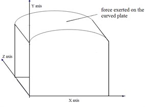
This paper presents a fast topology optimization formulation and numerical techniques of damping material layer were designed for sound reduction to a curved plate-cavity structure (as schematically illustrated in Fig. 4).
For weight limit reason, damping material could not be pasted on all surfaces. Optimization principle is using less as far as possible the damping materials to reach more effective vibration or noise reduction. The computational model is based on a finite element discretization. Assuming pasting a small amount of damping material on the structural has little effect on vibration mode, the relationship between energy loss of the damping materials on each element and the displacement of each node of the plate (shell) is deduced in a vibration cycle. Principle of the topology optimization method is to paste damping materials on the more effective location, where the element energy will lose most and then the second gradually, until the noise reduction target was achieved. Usually, only one or several modal orders of the structure affect the noise or vibration most. Aimed at the appointed order, only one or several eigenvalues need to be calculated. It is unnecessary to solve a large complex differential equation or matrix eigenvalue. So it is considered as a kind of fast and approximate topology optimization method.
2. Vibration analysis of curved plate or shell structure
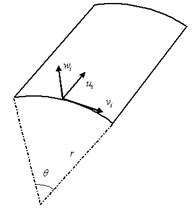
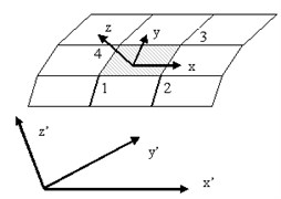
Middle plane of the shell is a curved surface (thin shell diagram and global coordinates and local coordinates of rectangular element are shown as Fig. 1). The displacement in the middle plane and the displacement perpendicular to the surface generally occur simultaneously. Bending state and membrane state are mutual coupling. Generally, there are two kinds of methods to analyze thin shell: one is to use plane element combining folded plate system to replace shell, which combined plane stress and bending stress together to replace the stress of the thin shell; the other is to adopt curved shell element or curved thick shell element directly. In theory, adopting the surface shell element can reflect the real shape of the shell, and obtain accurate results. For most of the mechanical structures are space plate structure or plate-beam combination structure, in this paper plane element was combined to a folded plate system to replace shell and its coordinates which is shown as Fig. 1. Plane stress and bending stress together are used to replace the stress of the thin shell. Element stiffness matrix of the shell is also the stiffness matrix combination of the two kinds of elements.
Fig. 1Sketch of the shell, global coordinates and local coordinates of rectangular element
In the four node quadrilateral plane element, for example, plane stress state has the following relation:
where superscript means plane stress. represents shape function of the plane stress model:
where , , which is dimensionless local coordinates. Length and width of the rectangle element are , respectively. Plate bending state has the following formula:
where superscript means bending stress. represents shape function of kirchhoff bending plate element. Let , , , , we get:
Combining plane stress and bending stress together. Put into node displacements vector. For local coordinate system, we get:
And in global coordinate system, node displacement vector is:
3. Energy analysis for free damping layer attached to curved plate or shell structure
Damping materials and base metal materials consolidated together. Suppose each layer of the structure is uniform. In the process of vibration, energy dissipation of each layer in one vibration period is equal to the loss factor of layer multiplying the maximum elastic deformation energy. For elastic plate:
Superscript (), () indicate membrane and bending state respectively, which is:
Shell strain can be decomposed into two parts, which are membrane strain and bending strain respectively. So the deformation of thin shell could also be divided into two parts: membrane strain energy and bending strain energy respectively. Strain energy of the shell can be expressed as:
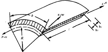
It is assumed that the strain of the free damping shell at time is . Within , the increment of the strain is , and the increment of the strain energy is . The strain energy per unit volume at time is , and the whole energy could be . For the shell is composed of damping material and metal material, the integral area should be these two parts. Then:
where means volume of metal plate, and means volume of damping material. Sketch of the shell with damping material is shown as Fig. 2.
When strain of the structure changed periodically, we get . Suppose that the base layer is composed of isotropic metal materials. Young’s modulus is , while Poisson’s ratio is , and the density is . The variation of the strain energy per unit volume in a cycle is:
The Eq. (11) above describes that the base layer, the metal plate do not experience energy decaying, and energy is unchanged. Constitutive relation of the free damping layer can be described as:
Using three parameters’ viscoelasticity solid modal, relaxation modulus is:
where, . Set integrating range is and set . Under periodical strain effect, can be calculated as:
The first part of the above Eq. (14) equals zero, which is corresponding to elastic vibration energy per cycle. The latter two integrals represent energy attenuation in a cycle, and the integral range is [0, ]. We get:
Solve the above Eq. (15):
When the time is long enough, the value of the second part of the Eq. (16) will verge to a constant . In a vibration steady state, the energy corresponding to the second part of the Eq. (16) attenuate close to zero. So it can be concluded that in steady state vibration, only second integral item needs to be considered, which is:
where represents strain vector at any point of the free damping layer.
3.1. The relationship between energy loss of the damping material on each element and the displacement of the nodes of the curved plate (shell) structure
The purpose of damping materials is to convert kinetic energy into heat energy to reduce the vibration of the thin plate. The way to determine the location where the damping material pasted on is to find the location where damping material’s energy will lose more.
Energy loss of damping material on each element in a vibration cycle is . Then can be expressed as , which also can be expressed by the node displacement of the base metal plate as below (Eq. (18)):
where:
where , and are membrane stiffness matrix, coupling stiffness matrix and bending stiffness matrix of the four nodes rectangular plate element respectively. Because the thickness of the shell and the damping layer are constants, the coefficients in Eq. (18) are also constants and independent to coordinate. Given:
Fig. 2Sketch of the shell with damping material layer
The Eq. (20) above can be simplified as:
According to the aimed order vibration mode of the metal plate, energy loss of damping materials on each element can be calculated by Eq. (21). Damping materials will be pasted on the element location where damping material energy will lose most, and then the second gradually, until the optimization target is achieved.
3.2. Modal acoustic transfer vector (MATV) and structural modal participation factor
Acoustic transfer vector is a corresponding relationship between structure surface and sound pressure of the measure point in a radiation sound field. Under the condition of small disturbance, it is considered that the acoustic equation of structural sound radiation is linear. That is to say, a linear relationship can be established between input (vibration on the surface of the structure) and the output (sound pressure of the specified point in the sound field). Which is:
where means sound pressure, means acoustic transfer vector, and means vibration velocity of the structure surface at normal direction.
Displacement of the structure is linear superposed through mode of the structure, which is:
where means mode of the structure. represents structural modal participation factor, which is the function of frequency. For , we get:
It is few modals that affect the vibration, aimed at which vibration or noise control can be more effective. According to modal acoustic transfer vector and structural modal participation factor, the most effective mode was found. The example is shown as Fig. 8.
4. Process of the fast topology optimization
From the view of energy, damping means energy attenuation. According to Eq. (21) the relationship between energy loss of the damping materials on each element and the displacement of each node in a vibration cycle, a fast topology optimization method for damping materials laid on elastic curved plate (shell) structure was established. Damping materials were pasted on the most effective location, which is the object of the damping topological optimization. Only one eigenvalue needs to be computed. And it is unnecessary to solve a large complex differential equation or matrix eigenvalue.
The optimization process is described as below:
1) Complex structures can be established by commercial finite element software. Matlab subroutines were produced to read out the finite element and node information. And also stiffness matrix, mass matrix, and the corresponding modal vibration mode were calculated.
2) It is few modals that affect the vibration, aimed at which vibration or noise control can be more effective. According to modal acoustic transfer vector or structural modal participation factor, the modal orders which have more influence on the vibration or noise reduction could be found.
3) One order modal can be optimized or make use of weighted factor several order modals can be optimized. According to the aimed order vibration mode of the metal plate, energy loss of damping materials on each element can be calculated by Eq. (21).
4) Supposing the optimized modal is th. Energy loss of damping material on each element in one vibration cycle was calculated. Paste damping materials on the location where energy loss the most, and then the second most. The rest can be done in the same manner, until achieve the optimization target. At the same time filter formula used effectively inhibit the checkerboard phenomenon.
5) Contrast the intensity of sound pressure of a specified point in the acoustic cavity before and after the optimization respectively, the validity of this method was verified.
Flowchart of the optimization process of pasting damping layer to elastic shell for vibration noise reduction is show in Fig. 3.
The method in this paper is quite different from evolutionary optimization techniques. Evolutionary optimization method requires multiple iterations and a small amount of elements are removed in each iteration. However the method in this paper is called fast topology optimization algorithm which only needs to compute one eignvalue of the metal plate. And also this method can be considered as a kind of approximate algorithm, for using Eq. (21) to calculate the energy loss is based on the vibration mode without pasting damping materials. Assuming that pasting a small amount of damping material has no effect on structural vibration mode, yet, there was always a little bit influence. For large structures, the influence of vibration mode with a small amount of damping materials pasted on is really small.
5. Example
Fig. 4 shows a curved plate and an acoustic cavity structure. Force was exerted on the curved plate. Acoustic radiation was produced mainly because of the forced plate. Damping materials were pasted on the surface of the forced plate. The topology optimization procedure is implemented in MATLAB, and the flowchart is given in Fig. 3.
Fig. 3Flowchart of the optimization process
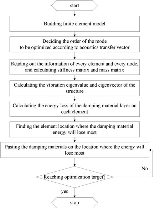
Fig. 4Sketch of curved plate – cavity structure
The length-width-height of the curved plate-cavity structure respectively is 1.2 m×0.6 m×1.0 m. Material parameters of metal layer and damping material layer are presented in Table 1.
Table 1Material parameters of metal layer and damping material layer
The type of layer | Elasticity modulus | Poisson’s ratio | Density |
Metal layer | 210 GPa | 0.3 | 7800 kg/m3 |
Damping layer | 70 GPa | 0.3 | 800 kg/m3 |
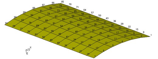
First of all, finite element model of the curved plate-acoustic structure was built by the finite element software. Curved plate model is shown as Fig. 5.
Fig. 5Node distribution on the curved plate
The elastic curved plate-cavity structure can be simulated for a driving cab. Sound pressure at the point of person’s ear was considered. The information of elements and nodes were read out, frequency and vibration mode were calculated by Matlab subroutines. Commercial sound simulation software was used to determine the order of the plate to be optimized.
Fig. 6Node distribution and the specified node (85) in the cavity
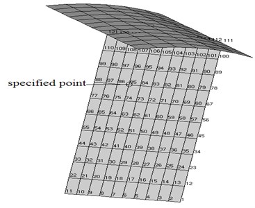
For specified point as shown in Fig. 6, the order of the mode affect the level of the sound pressure most is different. According to modal acoustic transfer vector, the plate (shell) mode which affects the sound pressure of the specified point most was found. Fig. 7 shows transfer function between structural modal and point in the cavity.
From the Fig. 7 above, we get that the third order modal of the plate has the largest influence on the sound pressure of the specified point 85. So aimed at the third modal, using the method described in this paper, and according to the flowchart of the optimization process Fig. 4, the result of the damping layer sticking position diagram is shown in Fig. 9. Setting the finial damping layer occupy half of the whole area. The optimization process can be sketched as: 1) Building finite element model take advantage of commercial finite element software; 2) Writing MATLAB programme, reading out the information of every element and every node, and calculating stiffness matrix and mass matrix; 3) Calculating the vibration eigenvalue and eigenvector of the curved-plate; 4) Calculating the energy loss of the damping material layer on each element according to Eq. (21); 5) Pasting the damping materials on the location where the energy will lose most until reaching optimization target.
Sound pressure level at specified point was calculated taking advantage of commercial sound simulation software. Two models were established for curved-plate without damping layer and with damping layer respectively. And these two modes were meshed in finite element software. Exerting force to the structure model, displacement response of each node was calculated and saved, which would be imported to sound simulation software. According to these displacement response of each node, sound pressure level at specified point was calculated, which was shown as Fig. 9. Two pictures represent two cases the curved plate with damping materials and without damping materials respectively. The figures show that in the low frequency area sound pressure is decreased obviously.
Fig. 7Modal acoustic transfer vector to specified point 85 in the sound radiation field
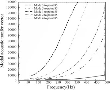
Fig. 8Location of the damping material after optimization
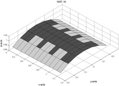
Fig. 9Sound pressure level at the specified point
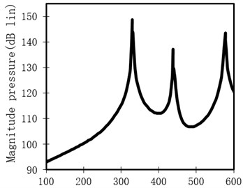
a) Before optimization
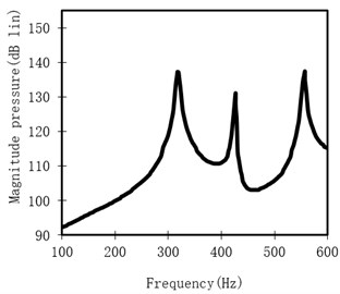
b) After optimization
6. Conclusions
In this paper, a fast topology optimization method of damping material layer for noise reduction to elastic curved plate-cavity structure was given. Only calculating one eigenvalue can get approximate optimal distribution of damping material layer, so the topology optimization method is a kind of approximate and fast method.
The purpose of the topological optimization is to use less as far as possible the damping materials to reach the best result of vibration or noise reduction effect. Finite element model was established by commercial software which is easy for complex structure. Write Matlab subroutines to read out nodes and elements information of the model, calculate the stiffness matrix, mass matrix, and the corresponding modal vibration mode. According to modal acoustic transfer vector or structural modal participation factor, the order of the mode to be optimized was decided. Aimed at the order to be optimized, energy loss of damping material on each element in a period was obtained. Paste damping material on the location where the damping material energy would lose most, and the second most gradually, until optimization target was achieved. Numerical example results show that this method is simple, suitable for engineering application.
References
-
Li Hong-qiu, Chen Guo-ping, Zhang Bao-qiang Topology optimization design of constrained layer damping plate-cavity system considering vibro-acoustic coupling. Journal of Vibration, Measurement and Diagnosis, Vol. 10, 2011, p. 586-590.
-
Smith D. C., Bernhard R. J. Computation of acoustic shape design sensitivity using a boundary element method, numerical techniques in acoustic radiation. Winter Annual Meeting of ANME, SAN Francisco, California, 1989, p. 109-116.
-
Wolfgang A. W., Moritz A. F., Christian C. Isogemetric structural shape optimization. Compute Methods Applied Mechanics and Engineering, Vol. 97, Issue 33, 2008, p. 2976-2988.
-
Hilmann J., Pass M., Haenschke A., Automatic concept model generation for optimization and robust design of passenger cars. Advances in Engineering Software, Vol. 38, 2007, p. 795-801.
-
Renato Barbieri, Nilson Barbieri Finite element acoustic simulation based shape optimization for a muffler. Applied Acoustic, Vol. 67, 2006, p. 346-357.
-
Marburg S., Beer H. J., et al Experimental verification of structural –acoustic modeling and design optimization. Journal of Sound and Vibration, Vol. 252, Issue 4, 2002, p. 591-615.
-
Zaiwei Li, Xinhua Liang Vibro-acoustic analysis and optimization of damping structure with response surface method. Materials and Design, Vol. 28, 2007, p. 1999-2007.
-
Eddie Wadbro, Martin Berggren Topology optimization of an acoustic horn. Computer Methods in Applied Mechanics and Engineering, Vol. 196, 2006, p. 420-436.
-
Bendsøe M. P., KikuchiN.Generating optimal topologies in structural design using a homogenization method. Computer Methods in Applied Mechanics and Engineering, Vol. 71, 1988, p. 197-224.
-
BendsøeM. P. Optimal shape design as a material distribution problem. Structural Optimization, Vol. 1, 1989, p. 193-202.
-
Zhou M., RozvanyG. I. N. The COC algorithm, part II: topological, geometry and generalized shape optimization. Computer Methods in Applied Mechanics and Engineering, Vol. 89, 1991, p. 197-224.
-
SigmundO. A 99 line topology optimization code written in Matlab. Structural and Multidisciplinary Optimization, Vol. 21, 2001, p. 120-127.
-
Wang M. Y., Wang X. M., GuoD. M. A level set method for structural topology optimization. Computer Methods in Applied Mechanics and Engineering, Vol. 192, 2003, p. 227-246.
-
Allaire G., Jouve F., ToaderA. M. Structural optimization using sensitivity analysis and a level-set method. Journal of Computational Physics, Vol. 194, Issue 1, 2004, p. 363-393.
-
Pasi Tanskanen A multi objective and fixed element based modification of the evolutionary structural optimization method. Computer Methods in Applied Mechanics and Engineering, Vol. 196, 2006, p. 76-90.
-
Diaz A. R., KikuchiN. Solutions to shape and topology eigenvalue optimization using a homogenization method. International Journal for Numerical Methods in Engineering, Vol. 35, 1992, p. 1487-1502.
-
PedersenN. L. Maximization of eigenvalues using topology optimization. Structural and Multidisciplinary Optimization, Vol. 20, Issue 1, 2000, p. 2-11.
-
Du J., OlhoffN. Topological design of freely vibrating continuum structures for maximum values of simple and multiple eigenfrequencies and frequency gaps. Structural and Multidisciplinary Optimization, Vol. 34, 2007, p. 91-110.
-
Takezawa A., Nishiwak S., IzuiK., Yoshimura M. Structural optimization based on topology optimization techniques using frame elements considering cross-sectional properties. Structural and Multidisciplinary Optimization, Vol. 34, Issre 1, 2007, p. 41-60.
-
Sigmund O., JensenJ. S. Systematic design of phononic band-gap materials and structures by topology optimization. Philosophical Transactions of the Royal Society of London Series A-Mathematical Physical and Engineering Sciences, Vol. 361, 2003, p. 1001-1019.
-
Araújo A. L., Madeira J. F. A., Mota Soares C. M., Mota Soares C. A. Optimal design for active damping in sandwich structures using the direct multisearch method. Composite Structures, Vol. 105, 2013, p. 29-34.
-
Erik Andreassen, Jakob Søndergaard Jensen Topology optimization of periodic microstructuresfor enhanced dynamic properties of viscoelastic composite materials. Structural and Multidisciplinary Optimization, Vol. 49, 2014, p. 695-705.
-
Shu L., Wang M. Y., Fang D., Ma Z. D., Wei P. Level set based structural topology optimization for minimizing frequency response. Journal of Sound and Vibration, Vol. 330, 2011, p. 5820-5834.
-
Xiaopeng Zhang, Zhan Kang Topology optimization of damping layers for minimizing sound radiation of shell structures. Journal of Sound and Vibration, Vol. 332, 2013, p. 2500-2519.
-
Smith D. C., Bernhard R. J. Computation of acoustic shape design sensitivity using a boundary element method, numerical techniques in acoustic radiation. Winter Annual Meeting of ANME, SAN Francisco, California, 1989, p. 109-116.
-
Christensen S. T., Sorokin S. V., OlhoffN. On analysis and optimization in structural acoustics –part I: problem formulation and solution techniques. Structural Optimization, Vol. 16, 1998, p. 83-95.
-
BosJ. Numerical optimization of the thickness distribution of three dimensional structures with respect to their structural acoustic properties. Structural and Multi disciplinary Optimization, Vol. 32, 2006, p. 12-30.
-
Luo J., GeaH. C. Optimal stiffener design for interior sound reduction using a topology optimization based approach. Journal of Vibration and Acoustics, Vol. 125, 2003, p. 267-273.
-
Du J. B., OlhoffN. Minimization of sound radiation from vibrating bi-material structures using topology optimization. Structural and Multidisciplinary Optimization, Vol. 33, 2007, p. 305-321.
-
Niu B., Olhoff N., Lund K., ChengG. D. Discrete material optimization of vibrating laminated composite plates for minimum sound radiation. International Journal of Solids and Structures, Vol. 47, 2010, p. 2097-2114.
About this article

This research has been supported by Doctoral Fellowship of Jinling Institute of Technology No. JIT-B-201219, Natural Science Foundation of China, No. 51305197, the Aeronautical Science Foundation of China under Grant No. 2012ZA52001, and Research Fund for the Doctoral Program of Higher Education of China No. 20123218120005.
