Abstract
The objective of this paper is to evaluate the aerodynamic effect of the high-speed train on an overpass cable-stayed bridge completed by the rotation method. Computational fluid dynamics software Fluent was used in this numerical study. Flow field under a high-speed train has been considered as a viscous, compressible and unsteady flow. Flow model of high-speed train and bridge was established by the sliding mesh approach. Simulated train is passing 7.25 m underneath the bridge with a speed of 350 km/h and 500 km/h to obtain the time history of lifting force, resistance force and torque such that those data can be later applied to the bridge under different construction stages. Numerical results showed that larger aerodynamic response was observed when the tail of the train passed the bridge and the maximum response was observed right above the train. As for current scenario, the aerodynamic effect on such type of concrete cable-stayed bridge could be ignored but it should be checked when structure became lighter (such as steel structure).
1. Introduction
Nationwide construction of high-speed rail (HSR) network is still ongoing in China and railway lines are overlapped each other when approaching to the railway stations. Near a station, the rotation method is usually chosen to build a bridge across other existing lines such that current operation of other lines will not be interrupted. During the rotation process, high-speed trains will pass underneath the bridge frequently such that the structure may be subjected to significant aerodynamic loading. It is well known that the high-speed train can generate an unsteady, viscous and turbulent flow field surrounding the body of the train, which may trigger the instability of the structure and passing trains nearby. Certain studies have been carried out in past two decades to evaluate the aerodynamic effect of a running train on adjacent trains, sound barrier and even human body [1], and simplified calculation approach has been issued in specifications to estimate the aerodynamic pressure from the running trains [2, 3]. But most studies to date only focused on low-speed train (i.e. below 350 km/h) and the aerodynamic effect of high-speed train on surrounding structures is lack of study.
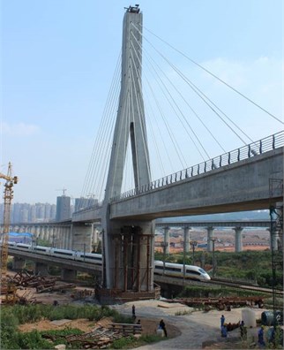
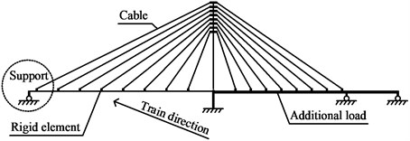
In present study, the overpass structure above the existing Wuhan-Guangzhou HSR line (intersecting angle is 15°) is a single tower prestressed concrete cable-stayed bridge with a three-span arrangement (112+80+32 m), which is part of the Shanghai-Kunming HSR line located near the new HSR station at the city of Changsha, as shown in Fig. 1. The design speed on the Wuhan-Guangzhou HSR line is 350 km/h. The objective of this study is to evaluate the aerodynamic response of this cable-stayed bridge under various construction periods, including rotation process, completed stage and operation stage. The flow field of the high-speed train and the numerical mode of the bridge were simulated through the computational fluid dynamics software.
Fig. 1Built single tower cable-stayed bridge
2. Analysis of aerodynamic force on cable-stayed bridge
The flow field was assumed as a viscous, compressible and unsteady field. The equation turbulence model was used for the turbulence flow, selecting the segregated solver. The continuity equation, momentum equation, equation were used as control conditions [4].
Considering the aerodynamic characteristic of train mid-sections is similar, the CRH3 (China Railway High-speed No. 3) train model consists of train head (25.25 m), intermediate (25 m) and tail (25.25 m). The train surface was simulated with smooth curved surface to improve the computing efficiency [5].
Both computational domain of the train and the bridge (considered as rigid object) were established by the sliding mesh method. The entire numerical model consists of 2.19 million elements. For the boundary conditions, the train surface was set as the slip surface (slip velocity was the train speed), and the other surfaces were non-slip surfaces [6, 7]. In addition to analyzing the train maximum operating speed 350 km/h, another possible scenario of increasing train speed was considered. The train speed was increased to 500 km/h so as to simulate the aerodynamic effect of train on the bridge at the ultimate limit state. The clearance between the rail and the bridge above is 7.25 m.
Fig. 2Schematic diagram for aerodynamic data partitioning
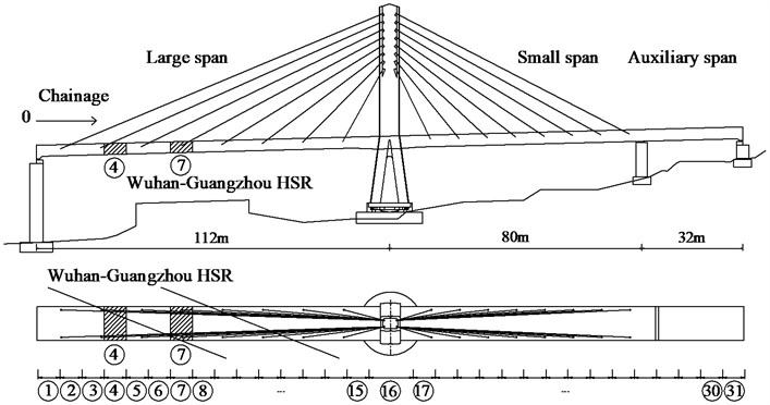
The cable-stayed bridge was divided into 31 sections (7 m per section, shown in Fig. 2). The surface pressure of each section was calculated through iterative calculation of flow field. Pressure difference between the upper and lower surfaces of the bridge was integrated to obtain the lift force that applied to bridge; integrating the upwind side and downwind to obtain the resistance force; take the centroid of the cross-section of bridge as enter to calculate the torque due to the lift force and resistance force.
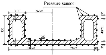
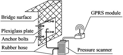
In the test, the time history of wind data was collected by using pressure sensors installed on the lower part of each section and the side of the cross-section of the bridge. These test data were sent to a computer server through the embedded data acquisition module and GPRS module when high-speed train passed the bridge, see Fig. 3. These data were then received by the manager for an estimation of wind pressure in order to obtain the response curve of lift force, resistance and torque.
Fig. 3Test method of wind pressure on bridge: a) Pressure sensor arrangement; b) Pressure test system
a)
b)
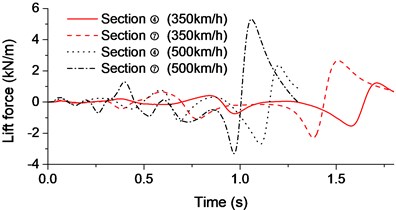
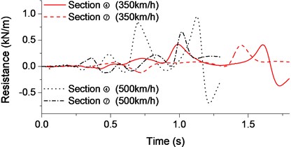
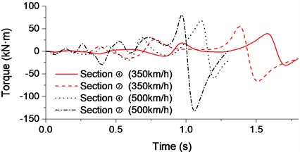
Taking Sections ④ and ⑦ (just above the train) of the bridge as examples, time-history analysis of the lift force, resistance and torque that applied to the beam were shown in Fig. 4 when the passing train speeds were respectively 350 km/h and 500 km/h.
Fig. 4Aerodynamic time-history curve for high-speed train: a) Lift force; b) Resistance; c) Torque
a)
b)
c)
It can be seen from Fig. 4, the peak of aerodynamic response did not occur at the time when the head of the train approached the bridge. Instead, a larger response can be observed when the tail of the train reached the bridge. The maximum response of the bream can be found at the cross-section right above train, i.e. the Section ⑦ on the beam. The aerodynamic force applied to the bridge was significantly increased with higher train speed.
3. Dynamic response of cable-stayed bridge in rotation
The construction of the overpass cable-stayed bridge might in the middle of rotation when a high-speed train passed underneath. In this case, the 32 m span still cannot link with the 80 m span. In order to ensure the balance on both sides of tower, additional load was applied to 80 m span side. When analyzing such dynamic response of overpass cable-stayed bridge under the train aerodynamic, the gravity of cable-stayed bridge was not included (but considering its mass). The 3D beam element with 6 degree of freedom was adopted to simulate the main beam and the rigid link was set on the beam element to accurately simulate the spatial location of cables. The rotational restraint of tower was provided by rotary ball hinge friction. Due to the short span of this bridge, the bar element was used to simulate the cables. Additional dead load was simulated as the mass element, without considering frictional resistance of the movable bearing. Tower and pier were simulated according to the actual geometrical dimension, and 6 equivalent stiffness springs were adopted to consider the pile-soil interaction.
Fig. 5Calculation model for cable-stayed bridge at rotational stage
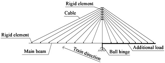
Fig. 6Displacement envelope of cable-stayed bridge at rotational stage: a) Vertical displacement of bridge; b) Horizontal displacement of bridge; c) Bridge torsion
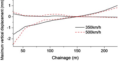
a)
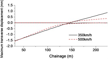
b)
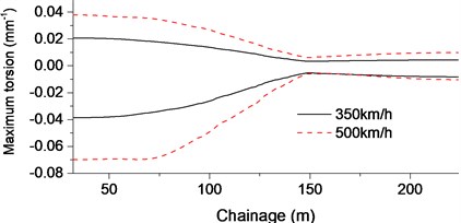
c)
The static friction coefficient of ball hinge is 0.1 and the dynamic friction coefficient is 0.05 (considered as 0.05 in this study). The radius of the ball hinge is 2 m with a rotational total weight of 145 MN. The friction torque of the ball hinge is approximately 9.6 MN·m. The built model was shown in Fig. 5.
The modal analysis of this bridge was carried out. The first modal shape is the horizontal rotation of the beam with a natural vibration frequency of 0.0944 Hz, which means that the rotational stiffness of the tower is small.
Time history of aerodynamic forces was obtained through the flow field analysis. The dynamic response of cable-stayed bridge was analyzed by applying those forces to each sections of the bridge. Load interval is 0.001 s and the total load duration is 1.3 s (500 km/h) and 1.8 s (350 km/h) including the aerodynamic peak. See Fig. 6.
When the train passed underneath the bridge with a speed of 350 km/h, the maximum vertical displacement of bridge is 1.6 mm that was observed on the side of 112 m; maximum transverse displacement is about 1.5 mm and maximum torsion is 0.03 mm-1 (350 km/h). At a higher speed of 500 km/h, the vertical displacement of bridge increased about 50 % and torque increased about 105 %.
4. Dynamic response of cable-stayed bridge after closure
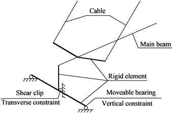
At the closure stage of cable-stayed bridge, both 80 m span and 32 m one were closed. Additional weight was only set on the 80 m span. Again, the rigid links were used between the tower and beam. Two movable bearings were set on the piers, and shear clips were set at the center of beam, shown in Fig. 7.
Fig. 7Diagram for cable-stayed bridge bearing arrangement
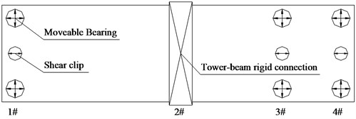
In order to consider the torsion caused by the aerodynamic force, the rigid elements on the main beam were used to make sure each cable, moveable bearing and shear clip in their right positions. The transverse displacement of bridge is restrained by the shear clips. And the moveable bearings only provides vertical supports (only pressure). The built model was shown in Fig. 8.
Fig. 8Detailed diagram for cable-stayed bridge analysis model: a) Calculation model of cable-stayed bridge after closure; b) Detail of support
a)
b)
Modal analysis of this bridge was carried out. First three natural frequencies are 1.0366 Hz, 1.1494 Hz and 1.7367 Hz. Vibration characteristics are: vertical bending at the longer span (112 m), lateral bending of the tower and the reverse bending of the main beam. Again, the vertical stiffness of the longer span side is small.
Under the aerodynamic force, the horizontal forces applied to bridge, shear clips and substructure were analyzed by applying lift force, resistance and torque with different train speeds, shown in Fig. 9.
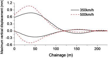
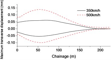
Fig. 9 shows that when the train ran at the speed of 350 km/h, the maximum horizontal force of shear clip is 51.5 kN; the maximum vertical displacement of beam on the 112 m span is 0.7 mm, the transverse displacement is 0.05 mm and the maximum torsion was 0.02 mm-1 under the aerodynamic force. When the train ran at the speed of 500 km/h, the maximum horizontal force of shear clips is 54.4 kN, the maximum vertical displacement of bridge is 1.3 mm (increasing about 85.7 %) and the transverse displacement increased to 0.09 mm (increasing about 80 %).
Fig. 9Cable-stayed bridge displacement and horizontal force envelope at closure stage: a) Vertical displacement of bridge; b) Horizontal displacement of bridge; c) Bridge torsion; d) Shear clips and tower horizontal force
a)
b)

c)
d)
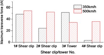
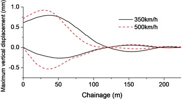
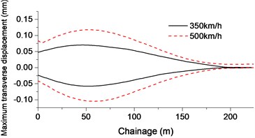
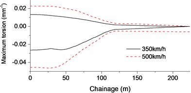
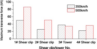
Fig. 10Cable-stayed bridge displacement and horizontal force envelope at operating stage: a) Vertical displacement of bridge; b) Horizontal displacement of bridge; c) Bridge torsion; d) Shear clips and tower horizontal force
a)
b)
c)
d)
5. Dynamic response of cable-stayed bridge in operation
During the operation, the weight of the ballast was all set on the entire bridge. Due to the changes of bridge and the restraints, first three natural frequencies of the bridge changed to 0.9482 Hz, 1.1321 Hz and 1.6803 Hz. After applying the aerodynamic forces of the train at different speeds, both transverse force and bridge displacement were analyzed, shown in Fig. 10.
The maximum horizontal force of shear clip is 50.3 kN (350 km/h) and 86.3 kN (500 km/h), and the maximum vertical displacement of bridge is 0.8 mm (350 km/h) and 0.9 mm (500 km/h). The transverse displacement is 0.07 mm (350 km/h) and 0.1 mm (500 km/h). After rounding up to 1 mm, it still satisfy the required limits of horizontal deflection on bridge [3]; the maximum torsion 0.03 mm–1 and 0.05 mm–1 of bridge could meet the requirement that less than 1.5 mm vertical deformation between two rails prescribed in the specifications [3].
6. Conclusions
Dynamic response of an overpass cable-stayed bridge due to aerodynamic effect of 350 km/h and 500 km/h high-speed train was analyzed in this paper. The main conclusions include:
1) The impact of high-speed train tail flow on the overpass was larger than the effect of the train head. The maximum lift force, resistance and torque applied are observed at the cross-section of the beam right above the passing train. Increasing speed of the train speed will lead to larger the aerodynamic force applied to the beam.
2) During the rotational stage, the running train results in a 1.6 mm vertical displacement and a 1.5 mm transverse displacement that will cause a significant vibration on the beam.
3) After the closure and during the operation, the aerodynamic force of the train will lead to a 50-80 kN horizontal forces on the shear clips and piers that cause an trivial vertical displacement (less than 1 mm) and transverse displacement (less than 0.1 mm).
4) In this case, the aerodynamic effect due to the high speed train on the prestressed concrete cable-stayed bridge can be ignored due to the large stiffness of the bridge, but the significant vibration could be found if the overpass bridge uses even lighter material, such as steel. In that case, a specific analysis must be required to ensure the dynamic response of bridge within an allowable range.
References
-
Orellano A., Wengle H. Numerical simulation (DNS and LES) of manipulated turbulent boundary layer flow over a surface-mounted fence. European Journal of Mechanics-B/Fluids, Vol. 19, Issue 5, 2000, p. 765-788.
-
Bsi U. National annex to eurocode 1: Actions on structures – part 2: Traffic loads on bridges, NA to BS EN 1991-2: 2003. British Standards Institution, 2008.
-
Ministry of Railways of the People’s Republic of China. Code for Design of High Speed Railway. China Railway Publishing House, 2010.
-
Yu Z., Weiqi Q., Youqi D., Mingsheng M. Introductory analysis of the influence of Menter’s k-ω SST turbulence model’s parameters. Acta Aerodynamica Sinica, Vol. 28, Issue 2, 2010, p. 213-217.
-
Chen Y. The study of aerodynamic effects of high-speed train induced wind and its effect on Cable-stayed Bridge crossing line. Central South University, 2003.
-
SchetzJ. A. Aerodynamics of high-speed trains. Annual Review of Fluid Mechanics, Vol. 33, Issue 1, 2001, p. 371-414.
-
Li R., Zhao J., Zhang S., Peng Y. Influence of the aerodynamic force to human body near high-speed trains. China Railway Science, Vol. 5, 2007, p. 22.
About this article

The first author is a researcher at Post-doctoral fellow of Traffic Engineering of Central South University. The authors would like to acknowledge Mr. Nan Hu from Michigan State University for language checking and constructive comments on this paper.
