Abstract
Magnitude of the impact test for spacecraft is generally required to be between 1000 g and 2000 g, moreover, the magnitude of some products is more than 3000 g. For high-magnitude impact test of large products, it is difficult for film impact test and drop impact test to meet the test requirements. In order to solve those problems, this paper designed a pneumatic impact test which can perform a high-magnitude impact test, gave the principles of the design and the diagram of the composition of the pneumatic test system, introduced the process and methods of the design of the pneumatic test system, which proposed a theoretical basis for the impact system.
1. Introduction
Since the GJB1027A has issued, space products now are advised to use shock response spectrum (SRS) test to replace classical shock test on ground explosion shock environment simulation in development stage. The way of space products SRS test at present goes as follows: 1) shaker excitation; 2) pendulum machine excitation; 3) drop shock machine excitation. The domestic pendulum machine’s load capacity is 100 kg, breaking frequency lays between 300 Hz and 1000 Hz, full load SRS level is no more than 2000 g. For the test articles whose mass is over 100 kg, SRS test level is over 2000 g, such test method above cannot accomplish the test. Based on the theory that compressed air momentary expansion generates high speed shock effect, through theoretical analysis, computation and practical experience, this paper proposed a method which can help design a horizontal pneumatic SRS test system in order to perform big mass, large size and high magnitude shock test.
2. Constitution and principle
The mass block of pneumatic test system pushed by compressed air momentary expansion impacts metal board which has multi order natural frequency (as shown Fig. 1). The metal board will be then set up resonance. By adjusting the mats located before and behind the systolic plate, the response of the systolic plate will be similar to attenuated sine wave which is used to simulate explosion shock environment.
Fig. 1The pneumatic test system for SRS
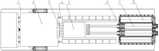
Composition of the system are as follows: 1 base, 2 systolic plate, 3 impaction plate, 4 guide track, 5 shock hammer, 6 piston pushing pole, 7 air cylinder, 8 air reservoir. Among these above, shock hammer, piston pushing pole, air cylinder, and air reservoir altogether constitute the impact components. Systolic plate supplies mounting interfaces for test article and generate resonance response in accordance with spectrum reference. The function of air cylinder and air reservoir is to apply power source of shock test. Mass block is kinetic component whose function is to impact systolic plate in high speed with the help of compressed air momentary expansion.
3. Theoretical design and analysis
3.1. Theory
The pneumatic test system mentioned above can be simplified as several different single degree of freedom (SDOF) spring-mass systems. For each SDOF system, first calculate SRS, then composite them to get the whole system SRS. Fig. 2 is horizontal SRS test system’s SDOF mass-spring-damp model.
Fig. 2The single-freedom model of SRS system
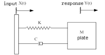
When systolic plate’s initial displacement and velocity is 0, the equation of the model is:
For the pneumatic SRS test system, the key point is design and analysis of systolic plate and impact components.
3.2. Systolic plate design and analysis
The following factors of systolic plate should be taken into consideration: mass of test article, size, frequency range, magnitude, breaking frequency, mounting method, material damping coefficient, geometry and etc. Like the design method of pendulum machine, modal analysis, frequency response analysis, strength analysis and SRS analysis are necessary. Breaking point adjustable is crucial. According to design principle of SRS test machine, only boundary condition is fixed and natural frequency appears at breaking point, SRS in accordance with test specification can be realized through adjusting the impact power and wave generator.
The method of design and analysis is as follows: 1) choose material, generally LY12 will be chosen; 2) design systolic plate shape and size, be sure that first order main modal is lower than lowest breaking point frequency with the help of finite element analysis (FEA); 3) determine the way of mounting to the base by simulation with various displacement restriction load; 4) check the strength, check the strength using maximum test level and leave enough safety margin.
3.3. Impact components design and analysis
The design of impact components is mainly about the mass of impact hammer, air cylinder, the diameter of air reservoir and run distance of piston pushing pole.
Given systolic plate’s natural frequency is , peak value of impact acceleration is , minimum impulse time is , impulse load duration time when impact hammer impact systolic plate is almost the half of periodic time.
When peak value of impact acceleration is , the velocity of systolic plate is:
where:; is modifying factor, generally the value is between 2.5 and 5.
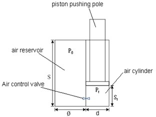
Given allowed run distance of piston pushing pole is , inner diameter of air cylinder is , inner diameter of air reservoir is , air reservoir zero hour pressure is , intermediate hour pressure is , corresponding piston run distance is , mean pressure inside the air cylinder is , as is showed in Fig. 3.
Fig. 3Pressure at discretionary time
During impact process, if pressure inside the air reservoir is stable, at any time it can be expressed as:
According to force equilibrium principle, such equation can be established:
where is standard atmosphere pressure; refers to friction coefficient.
Solve Eq. (3), (4), impact hammer velocity at the time of can be showed as:
The velocity when impact hammer impacts systolic plate () is:
Given the mass of systolic plate and product is , the mass of impact hammer is , the process of impact hammer impacts systolic plate follow elastic collision theory, according to energy conservation law, can be expressed as:
where is energy loss factor.
From the formula above, assume the diameter of air cylinder and air reservoir is the same. Such equation can be got:
As a result, the mass of impact hammer, the diameter of air cylinder, run distance of impact hammer can be got according to maximum magnitude of test reference.
4. Test and verification
Take length × width (1.25 m×1.25 m) systolic plate as an example to verify the design method, aluminum is chosen as the material of systolic plate. The specification of design is as follows: load capacity 200 kg, maximum test level with full load 5000 g, breaking point frequency range 400 Hz-2500 Hz.
Finite element analysis is taken at first, the thickness of systolic plate is 80 mm, 3 guide track and 6 sliding block are used in mounting, the first order natural frequency is approximately 389 Hz, the mass of it is 216 kg.
Secondly, determine the physical quantity as follows: 0.7 MPa, MPa, , when full load, .
Generally, the breaking point of high test level is greater than low test level. Given impact test level 5000 g, breaking point frequency 1200 Hz, impact energy needed is equal to test level 2000 g, breaking point frequency 400 Hz. Formular can be simplified as:
Several different parameter groups are used to do calculation. For instance, , diameter of air cylinder 0.2 m, then run distance of piston pole . Take these parameters above into Eq. (9), the velocity when impact components impacts systolic plate can be got, which is 7.2 m/s, far higher than impacting velocity of domestic pendulum machine. That means more impact energy and test level available.
Fig. 4Pneumatic test machine for SRS
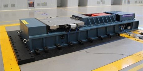
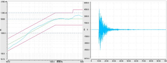
Based on design proposal, a pneumatic test machine with 1.25 m×1.25 m systolic plate is made (as is shown in Fig. 4), after we carrying on a test on the machine, test result acquired is ideal, 400 Hz-2500 Hz breaking point adjustable and 8000 g with full load are realized. Fig. 5 is the test curve when the load is 196 kg, test reference is 100-1500 Hz, 6 dB/oct, 1500-5000 Hz, 5000 g. SRS conform to test specification. Time domain curve is similar to explosive shock attenuated spectrum.
Fig. 5The test result (frequency: Hz, time: ms, load: 196 kg)
5. Conclusion
This paper provided a design and analysis method of high range pneumatic test system for shock response spectrum. Compared with traditional mechanical shock response system, horizontal style pneumatic test system for shock response spectrum has greater advantages. Instantaneous shock velocity has been enhanced a lot due to air actuated plant application, which can effectively increase test level. Time domain curve is similar to explosion shock attenuated spectrum. Impact time can be strictly controlled within 10 ms. Based on the design and analysis method introduced in this paper, the pneumatic test system in accord with client demand can be developed.
References
-
Jianhua Zhang Pyroshock environment of missiles and launch vehicles. Missiles and Space Vehicles, 2005, p. 30-35.
-
Bo Hao Design of Pendulum impact testing system. Beijing University of Technology, 2006.
-
Peng Xu, Jing Zu, Jing-Biao Fan Acceleraton shock test technology with higher values of G. Journal of Vibration and Shock, Vol. 30, Issue 4, 2011, p. 241-244.
-
Bin Wu, Liming Li Design of dual-horizontal shock test apparatus. Journal of Vibration Measurement and Diagnosis, Vol. 22, Issue 4, 2002, p. 310-314.
-
Fei Wang, Benlou Pi, Weigan Feng Experiment research of pneumatic pyroshock environment simulation device. Structure and Environment Engineering, Vol. 38, Issue 4, 2011, p. 16-19.
-
Barrett Peter, Cornford Steven L., Larson Calvin N. Pyroshock testing using large resonant plates and SRS theory using time and frequency domain methods. JPL, 2002.
-
Smith Strether, Hollowell Bill A proposed method to standardize shock response spectrum analysis. Journal of the Institute of Environmental Sciences, 1996.
About this article

