Abstract
An experiment on the vibrational characteristics of a hybrid gas bearing-rotor system in a 45 kW high-speed permanent magnet machine test rig is conducted. Nonlinear methods of measurements and analyses, including bifurcation maps, frequency spectra, and axis orbits, are adopted to evaluate sub-synchronous vibration in rotor acceleration. The effects of bearing supply pressure and speed accelerating rates on the stability of the gas bearing-rotor system are determined. Experimental results show that half-speed whirling of the gas film is eliminated and the start of gas film whipping is delayed by using the appropriate bearing supply pressure plan, thereby improving stability. Meanwhile power frequency vibrational amplitude is the smallest during the acceleration process, including the critical speed, when the appropriate speed accelerating rates are employed.
1. Introduction
High-speed permanent magnet (PM) machine technology is a key technology in micro or small turbine engines and high-speed motors. A structural feature of high-speed PM motors is the PM rotor, which prevents excitation loss and significantly increases efficiency. The rotation speed of the PM rotor ranges from tens of thousands revolutions per minute (r/min) to several hundred thousands r/min, and its circumferential velocity can reach up to 200 m/s. The current frequency of the stator winding can achieve 1000 Hz.
The Royal Institute of Technology in Stockholm began studying high-speed PM motors [1] in the mid-1980s, during which they developed a rotor with a rated speed of 100000 r/min and a rated power of 20 kW. This rotor employed non-magnetic steel to protect the PM. Stress calculation for a motor rotor was also conducted. The rotational speed of the motor in the experiment reached 75000 r/min. Reference [2] discusses solid-rotor induction machines and PM synchronous motors for high-speed applications. The authors compared three induction and three PM machines with the same operation points. They suggested that if the design (mechanical and thermal) is developed successfully, then the PM machine can provide the best operating characteristics for most high-speed applications. Calnetix Inc. developed a high-speed PM motor for shipboard applications, which provides power of up to 2 MW at a rotational speed ranging from 19000 r/min to 22500 r/min [3].
The stability of the hybrid gas bearing-PM rotor system, which includes the coaxial compressor and the turbine, is important in high-speed PM motors.
The present study investigates the effects of bearing supply pressure and accelerating rates on the stability of a bearing rotor based on a 45 kW high-speed PM motor test rig. The methods for restraining and eliminating low-frequency vibration are discussed.
2. 45 kW high-speed PM motor test rig
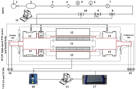
The test rig for a 45 kW high-speed PM motor consists of a vibration signal testing and analysis subsystem (VSTAS), a bearing supply pressure subsystem (BSPS), a 45 kW high-speed PM motor test bench body, and a frequency conversion driving subsystem (FCDS), as shown in Fig. 1. A screw-type air compressor, control pipes, flow sensors, temperature sensors, and pressure sensors make up the BSPS. The FCDS comprises a transducer and connecting cables. The VSTAS includes eddy current displace sensors, accelerometers, and a data-collecting instrument. The 45 kW high-speed PM motor test bench body consists of hybrid gas lubrication bearings, a PM rotor, a stator winding, and a chassis [4].
The 45 kW high-speed PM motor has a rated speed of 60000 r/min and a rated power of 45 kW. The stator winding has a Y-triphase and two-stage form. The cooling system uses air as working fluid. The exterior of the 45 kW high-speed PM motor is 580 mm long, 400 mm wide, and 325 mm tall.
Fig. 1Test rig of the 45 kW high-speed PM motor: 1. Air compressor 2. Gas tank 3. Filter 4. Dryer 5. Pressure gauge 6. Thermometer 7. Flow meter 8. Pressure stabilizing valve 9. Regulation valve 10. Safety shut-off valves 11. PM rotor 12. Stator wingding 13. Radial-thrust hybrid bearing 14. Radial hybrid bearing 15. Thrust bearing 16. Eddy current displace sensor 17. Data acquisition 18. Transducer 19. Computer
2.1. Hybrid gas lubrication bearings
Two hybrid gas radial bearings and a hydrostatic thrust bearing are adopted in the gas bearing-rotor system.
A schematic of the gas hybrid bearing is shown in Fig. 2. Dynamic lubrication is provided by the herringbone grooves distributed evenly on the inner surface of the bearing. The load-bearing capacity of the thrust bearing is attributed to the 32 orifices along the circumference. Table 1 presents the geometric characteristics of the hybrid bearings [4].
2.2. PM motor rotor and stator
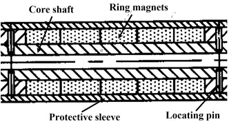
The PM motor rotor includes protective sleeves, two shaft ends, a core shaft, and ring magnets consisting of semicircular magnets. The shaft ends and the core shaft have interference-fit connections, and locating pins are used to fix the connections. The shaft ends are connected to the PM motor housing through the gas bearings. The ring magnets are pinned to the core shaft using a high-temperature glue. The magnets are divided into five segments along the axis.
This structural design has the advantages of a uniformly distributed mass, a simple manufacturing process for the ring magnets, and easy installation (Fig. 3).
Table 2 shows the geometric characteristics of the PM motor rotor. The stator for the 45 kW PM motor is found outside the rotor. The stator is 5 mm longer than the total ring magnets. The stator is assigned symmetrically relative to the center of the ring magnets. The interior of the stator is grooved with 36 chutes. The stator winding has a triphase and two-stage form, which has 36 turns. Each chute has a turn and each phase has 12 turns [5].
Table 1Geometric characteristics of the gas hybrid bearing
Geometric parameters | Values |
Bearing width, mm | 60 |
Number of orifices | 20 |
Nominal diameter, mm | 50 |
Distance of adjacent rows of orifices, mm | 34.58 |
Number of hydrodynamic groove | 20 |
Fig. 2Schematic of the gas hybrid bearing
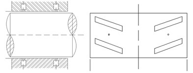
Table 2Geometric parameters of the PM motor rotor
Parameters | Values |
Total length of the rotor, mm | 575 |
Length of core shaft, mm | 200 |
Total length of ring magnets, mm | 150 |
Diameter at bearing, mm | 50 |
Bearing span, mm | 358 |
Mass of total rotor, kg | 9.3 |
Fig. 3Local structure of the PM motor rotor
3. Vibrational experiments on the hybrid gas bearing-rotor system
3.1. Effect of bearing supply pressure on stability
The frequency converter parameters are the same during different experiments and the initial temperature of the stator coil is constant at 37.5°C, the low-frequency vibrational characteristics of the gas bearing-rotor system for the 45 kW high-speed PM motor are evaluated by changing the bearing supply pressure plans.
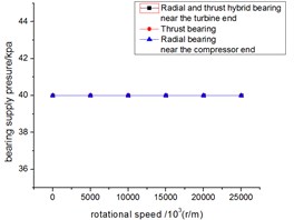
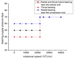
Two comparative experiments have been conducted. In the first experiment, we maintain the supply pressures for three bearings at 40 kPa during the entire acceleration process. In the second experiment, the bearing (radial and thrust hybrid bearings) supply pressure near the turbine end is set to 50 kPa when the rotor started, whereas the bearing supply pressure close to the compressor end is set to 60 kPa, and the thrust bearing supply pressure is set to 40 kPa. When the rotational speed reaches 22000 r/min, all the bearing supply pressures are increased to 70 kPa. The plans are described as Fig. 4.
Fig. 4Plans for the bearing supply pressure
a) Plan 1
b) Plan 2
Vibration displacement results are similar at the four measuring points, and the test results for the horizontal direction of the turbine end are discussed.
The waterfall plots for two different bearing supply pressure plans are shown in Fig. 5.
The bifurcation diagrams for two different bearing supply pressure plans are shown in Figs. 6 and 8, respectively. The speed accelerating rates for the two experiments have the same value (6.875 rad/s2). The spectral characteristics of the two speeds, which have been plotted using the frequency set for the analysis of the horizontal axis and the vertical vibrational amplitude, are shown in Fig. 7.
Fig. 5Waterfall plots for bearing supply pressure plan 1
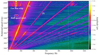
a) Plan 1
b) Plan 2
The bifurcation diagrams for two different bearing supply pressure plans are shown in Figs. 6 and 8, respectively. The speed accelerating rates for the two experiments have the same value (6.875 rad/s2). The spectral characteristics of the two speeds, which have been plotted using the frequency set for the analysis of the horizontal axis and the vertical vibrational amplitude, are shown in Fig. 7.
The critical speed for bearing supply pressure plan 1 is 7600 r/min, and the half-speed whirl occurs at 14700 r/min (Fig. 7). When the rotational speed reaches 18400 r/min, the bifurcation point appears, and the axis orbit exhibits a multi-periodic feature. The amplitude in the bifurcation diagrams increases with the rotational speed ranging from 18400 r/min to 22000 r/min.
The axis orbit during the occurrence of the half-speed whirl presents a periodic-2 characteristic (Fig. 7(a)), with a whirl ratio of 0.492 at the present moment. Three low-frequency elements, namely, 62.5, 125, and 187.5 Hz, are observed at 18600 r/min (Fig. 7(c)). Among the elements, the amplitude of 125 Hz is higher than those of the others, i.e., its frequency is close to the critical speed (7600 r/min). The low frequency at 125 Hz remains unchanged (Fig. 7(d)) with an increasing power speed of up to 20005 r/min. Therefore, the low frequency at 125 Hz is a gas film whip frequency. The axis orbit during gas film whip is shown in Fig. 7(b).
Fig. 6Bifurcation diagram for bearing supply pressure plan 1 (turbine end)
The experimental limit of the stable speed under bearing supply pressure plan 1 is at 18400 r/min (Fig. 6).
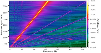
Fig. 8 gives bifurcation diagrams for bearing supply pressure plan 2 before the occurrence of the gas film whip. Half-speed whirl and gas-film whip disappear under bearing supply pressure plan 2; and the critical speed is at 8550 r/min. The frequency spectrum at 38900 r/min is shown in Fig. 9(a). The rotor maintains single-period stability during the speed-up process (Fig. 9(b)). Fig. 9(c) gives axis orbits at 39000 r/min after bifurcation point.
The following results are observed based on the two experimental conditions on gas bearing before and after the change in bearing supply pressure.
The critical speed increases with bearing supply pressure because the addition of bearing supply pressure increases the direct stiffness of the gas film.
Fig. 7Orbits and frequency spectra for bearing supply pressure plan 1
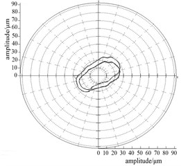
a) 14769 r/min
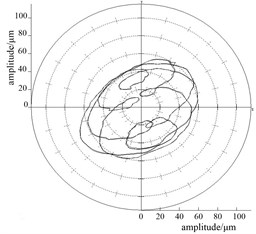
b) 19996 r/min
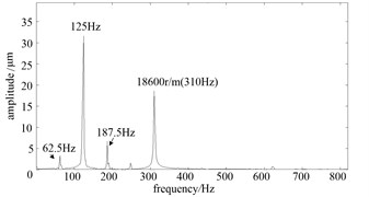
c) 18600 r/min
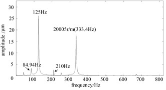
d) 20005 r/min
Fig. 8Bifurcation diagrams for bearing supply pressure plan 2 (turbine end)
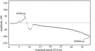
Fig. 9Frequency spectra and axis orbits for bearing supply pressure plan 2 (turbine end)
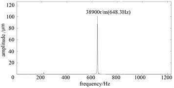
a) 38900 r/m
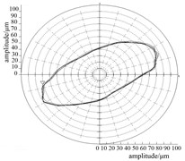
b) 34319 r/min
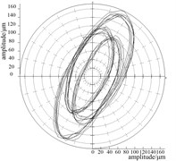
c) 39000 r/min
In bearing supply pressure plan 2, the half-speed whirl disappears at 14700 r/min, and the bifurcation point for the gas film whip is delayed to the speed of 38900 r/min. The stability of the gas-bearing rotor is significantly improved.
3.2. Effect of increasing speed rate on power frequency vibration
Power frequency vibration characteristics are evaluated by changing the increasing speed rate. Three different increasing speed rates, namely, 6.875, 11, and 13.75 r/s2 are used during the experiments under bearing supply pressure plan 2 (Table 2), which are set by changing the frequency converter parameters.
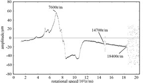
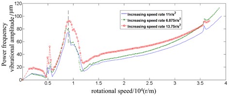
The power frequency vibrational amplitude from 0 r/min to 40000 r/min in the acceleration process under the three increasing speed rates is depicted in Fig. 10.
The vibrational amplitude for the increasing speed rate of 11 r/s2 is the smallest from 5300 r/min to 10400 r/min, including the amplitude at the critical speed. However, the critical speed of the bearing-rotor system (8550 r/min) is not affected by the increasing speed rate.
Therefore, an optimized increasing speed rate plan exists during acceleration to control the power frequency vibrational amplitude, even at the critical speed region and the design speed.
The regularity and the relevant mechanism analysis of experimental results for effect of increasing speed rate on power frequency vibration need further investigation.
Fig. 10Power frequency vibrational amplitude curve for the three speed accelerating rates (turbine end)
4. Conclusions
To improve stability in a gas hybrid bearing-rotor system for a 45 kW high-speed PM machine, this study investigated the dynamic characteristic effects of bearing supply pressure and speed accelerating rates, and discussed the nonlinear behaviors of whip and whirling instabilities. This study presented several simple and effective measures for enlarging the stable range of working rotating speed.
The instability characteristics for the gas hybrid bearing-rotor system remains to be sub-synchronous vibrations, including gas film half-speed whirling and whip, based on the experimental results. However, gas film whirling and whip can be eliminated and restrained by experimental methods listed in the paper.
A reasonable bearing supply pressure plan can eliminate gas film half-speed whirling and delay the start of the bifurcation point for gas film whip, which consequently increases up to rotational speed and keeps synchronizing.
Power frequency vibrational amplitude can be decreased by employing appropriate increasing speed rate plans during acceleration, particularly when the rotor passes the critical speed region. However, changes in speed accelerating rates cannot alter critical speed values. Several techniques presented in this study are easy to perform in engineering practice. The regularity and the relevant mechanism analysis of experimental results for effect of increasing speed rate on power frequency vibration need further investigation.
References
-
Chudi P., Malmquist A. Development of a small gas turbine driven high-speed permanent magnet generator. Licentiate Thesis, Stockholm, The Royal Institute of Technology, KTH, 1989.
-
Arkkio A., Jokinen T., Lantto E. Induction and Permanent Magnet Synchronous Machines for High-speed Applications. Electrical Machines and Systems, Vol. 2, 2005, p. 871-876.
-
Huynh C., Hawkins L., Farahani A., Mcmullen P. Design and development of a 2MW, high speed permanent alternator for shipboard application. Electric machines Technology Symposium, Philadelphia, 2004.
-
Han Dongjiang, Yang Jinfu, Geng Jiamin, et al. Vibration characteristics of gas bearing-rotor system of high-speed permanent magnet machine. Journal of Aerospace Power, Vol. 28, Issue 8, 2013, p. 1791-1796, (in Chinese).
-
He Min, Yang Jinfu, Geng Jiamin, et al. A high-speed permanent magnet motor. China, 2010, (in Chinese).
About this article

This work was supported by National Science and Technology projects (Grant No. 2012BAA11B02), and the support is gratefully acknowledged.
