Abstract
Dynamic response of assembled structures is strongly dependent on the mechanical behavior of joint interfaces. However, the effect of mechanical joints on structural dynamics is not yet fully understood due to the complex multi-scale, multi-physics and nonlinear characteristics of frictional contact interfaces. A monolithic beam without joint interfaces and a jointed beam with a typical shear lap joint are fabricated. Both structures are subjected to hammer impact excitation to identify the nonlinear effect of joint interfaces. The time-domain responses of both structures are first compared directly to identify the effect of joints. Experimental modal analysis is further used to yield mode shape, frequency and modal damping. The effects of joint interfaces on structural modal properties are investigated. Finally, the wavelet transform analysis and empirical mode decomposition are used to analyze recorded time-domain signals to quantify the effect of joint interfaces on dynamic behavior in time-frequency domain. The results show that joint interfaces play a critical role in dynamic response of assembled structure. The effective stiffness and damping of the lap joint bolt are amplitude dependent. Nonlinear effect of joints on dynamical response is obvious in high-frequency.
1. Introduction
Joint interfaces have a significant effect on dynamic response of assembled structures. They are considered as the major resource of energy dissipation and stiffness nonlinearity of complex structures [1, 2]. Identification and nonlinear modeling of joint interfaces is critical for simulation and prediction of dynamic behavior of these structures.
A number of experimental and theoretical investigations have been carried out to identify the nonlinear effect of joint interfaces [3-5]. Beards et al. [6] performed a series of experiments to characterize the joint damping. It is found that joint damping is much larger than material damping. Gaul et al. [1] carried out the dynamic experiments of a bolted structure, where a single-lap joint was located between two large masses. The results reveal hysteresis loop and nonlinear softening behavior between the tangential interfaces restoring force and relative displacement. Ma et al. [7] investigated the dynamic behavior of a jointed beam and a monolithic beam with identical geometry. It is shown that non-proportional damping and nonlinear softening stiffness are observed by the presence of joint interfaces. The similar procedure was used by Hartwigsen et al [5] to study the nonlinear effect of joint interfaces on the dynamics of a lap-jointed beam with a large great mass on each end. However, to characterize the effect of joint interfaces on the dynamic properties of a complex structure is still an open problem.
In this paper, a double-lap jointed beam and a monolithic beam with the identical geometry but without joint interfaces are subjected to a series of hammer impact tests. Several dynamic analysis methods are applied to analyze the recorded acceleration response. Time-domain response and FFT frequency-domain response of both structures are compared to identify the effect of joint interfaces. Experimental modal analysis method is used to pull out modal frequency and modal damping ratio. The identified modal parameters are compared. Finally, the recorded acceleration time-histories are analyzed by two time-frequency signal analysis methods, named wavelet transform analysis and empirical mode decomposition (EMD). Multi-scale nonlinear behavior induced by joint interfaces is characterized by these two time-frequency methods.
2. Experimental beam configurations
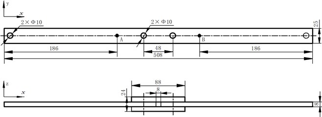
A jointed beam and a monolithic beam with identical geometry were fabricated. The geometry dimensions are shown in Fig. 1. Both beams are made of a low-carbon steel, consistent of a 508×25×8 mm3 simple beam with (jointed beam) or without (monolithic beam) a shear lap joint (88×25×8 mm3) in the central section.
An approximate free-free boundary condition was simulated by suspending the beam at their ends from the ceiling. The input excitations applied by model hammer were measured by the integral transducer at point A, and response accelerations on each beam were measured by miniature single-axial accelerometers attached at point B. All measured data was collected with a NI data acquisition cards and inputted to a PC to analyze the data.
Fig. 1The geometry of the experimental beam
3. Time-domain response analysis
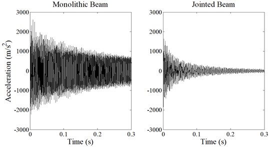
Fig. 2 shows the recorded acceleration response histories of the monolithic (left) and the jointed beam (right). It can be seen that the acceleration response of the jointed beam decays faster than the monolithic beam. Thus, a larger effective damping ratio can be expected for the jointed beam.
Fig. 2Acceleration response time histories of the monolithic and jointed beam
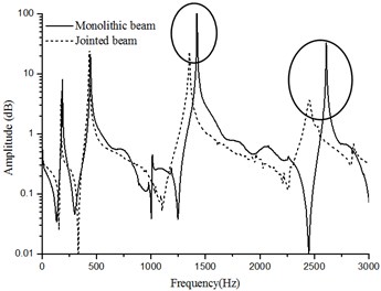
The FFT amplitude curves of both acceleration signals are illustrated in Fig. 3. It can be seen that at the low-frequency interval, both curves are similar, while for the high frequency interval, the differences are obvious. The peak frequencies of the jointed beam shift and are lower than the peak frequencies of the monolithic beam in high frequency modals. The peak amplitude of the jointed beam is smaller than the monolithic beam, which indicates larger damping ability. It is noted that for the third modal, the peak nearly disappears for the jointed beam.
Fig. 3FFT response amplitude of the jointed beam and the monolithic beam
4. Experimental modal analysis
Experimental modal analysis was used to extract the modal frequencies and modal damping ratio. The experiment schematic diagram is shown in Fig. 4 and the results are listed in Table 1.
Fig. 4The profile of modal analysis testing
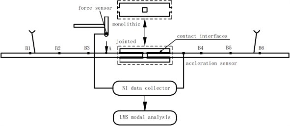
Table 1Modal analysis for frequency and damping
Mode | Frequency (Hz) | Damping ratios | ||
Monolithic | Jointed | Monolithic | Jointed | |
1 | 186.31 | 174.18 | 0.0004 | 0.0017 |
2 | 444.37 | 433.02 | 0.0027 | 0.0026 |
3 | 1013.08 | 952.43 | 0.0041 | 0.0090 |
4 | 1422.85 | 1353.73 | 0.0003 | 0.0035 |
5 | 2609.60 | 2454.44 | 0.0007 | 0.0077 |
It can be seen that the normal mode frequencies all decrease for the jointed beam compared with the monolithic beam. It turns out that the stiffness of the jointed beam is much lower than the monolithic beam due to the presence of the joint interfaces. The damping ratio of each mode of the jointed beam is much higher than the monolithic beam except for the second one. The reason may be that the node line of the second mode shape is located at the center of the beam. Displacement and velocity are nearly constant at the node line during a vibration cycle. Thus, the relative interfaces motion and resulted energy dissipation are both unobvious.
5. Wavelet transform and EMD
Time domain analysis and frequency analysis cannot give the insight of the system dynamic behavior in the time-frequency domain, while time-frequency analysis can give the multi-scale information of the system response. Wavelet transform and empirical mode decomposition are used here to perform the time-frequency analysis.
In mathematics, the wavelet series is a representation of a square-integrable (real- or complex-valued) orthonormal function. Nowadays, wavelet transformation is one of the most popular candidates of time-frequency-transformations.
The Hilbert-Huang transform (HHT) is designed to work well for data that is non-stationary and nonlinear [8, 9]. The core procedure of HHT is EMD [10]. The EMD method is a necessary step to reduce a given data into a collection of intrinsic mode functions (IMFs). Then the Hilbert spectral analysis can be applied to obtain instantaneous frequency data. An IMF is defined as a function that satisfies the following requirements:
1) In the whole data set, the number of extreme and the number of zero-crossings must either be equal or differ at most by one.
2) At any point, the mean value of the envelope defined by the local maxima and the envelope defined by the local minima is zero.
The IMFs can be calculated by the following procedure. Given that the time domain signal, contains distinct components at the dominant frequency resulting in the decomposition:
where, is the residual function and indicates the component associated with IMFs. The application of EMD yields IMFs sequentially from higher to lower frequency components. The main steps of the algorithm for extracting the IMFs of a signal , is summarized as follows: 1) find all peaks of ; 2) perform (spline-) interpolations between minima (maxima), resulting in an envelope and ; 3) compute the average ; 4) extract the residual detail ; and 5) iterate on the residual (inner loop that iterates) until the average can be considered zero-mean under some tolerance or monotonous series.
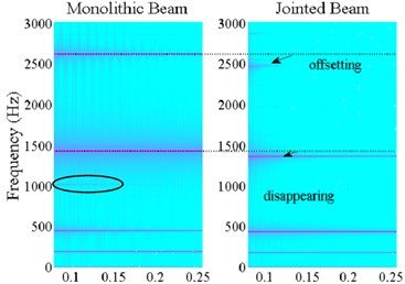
Fig. 5 shows the results of wavelet transform of the acceleration time domain response for the monolithic beam (left) ant the jointed beam (right). It can be seen that the high frequency time domain signal decay very fast due to joint damping. The peak frequencies of high frequency mode of the jointed beam are lower than the monolithic beam, which correspond to the results from experimental mode analysis. The third peak frequency, near 1000 Hz, disappears on the time-frequency plot of the jointed beam.
Fig. 5Wavelet transform of time domain response
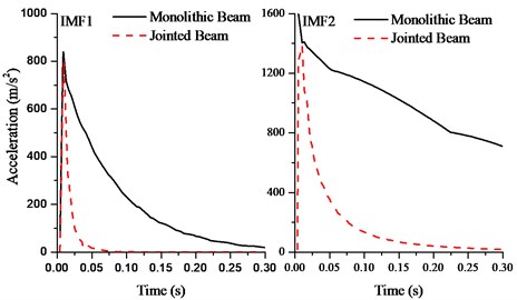
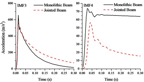
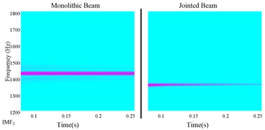
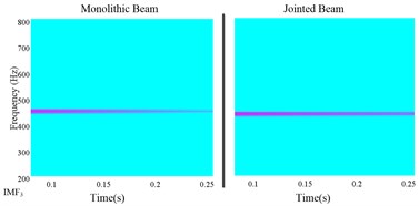
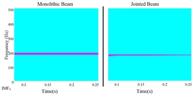
The amplitude envelopes of extracted IMFs for the monolithic and jointed beam are illustrated in Fig. 6. The IMF1 and IMF2 correspond to structural high frequency response component. It can be found that both signals decay very fast, which agrees well with the results from wavelet transform. Therefore, the joint interface plays a much more important role for structural high frequency response than low frequency. Joint damping is critical to control structural high frequency vibration.
Fig. 6The IMFs for impact excitation
a)
b)
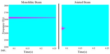
Fig. 7 shows the wavelet transform results of each extracted IMF. It can be seen that the central frequency of each IMF is corresponded to the modal frequency. The high frequency components decay very faster and after a short time, they disappear nearly. It is noted that for nonlinear identification of jointed structures, we must make full use of the short time interval high frequency response information to yield good identification results.
Fig. 7The wavelet analysis of each IMF
a)
b)
c)
d)
6. Conclusion
The aim of the paper is to investigate the effect of joint interfaces on structural dynamic behavior. Two experimental beams with identical geometry dimensions, one is a monolithic beam and the other is a jointed beam with mechanical joint interfaces. Both are subjected to hammer impact tests. Several dynamic signal analysis methods, including time-domain analysis, experimental mode analysis, wavelet transform, and EMD are used to give insights of the effect of joint interfaces on structural dynamic properties.
Compared with the monolithic beam, the stiffness of the jointed beam decrease and the damping increase due to the presence of the joint interfaces. The interfaces effect on structural dynamic response mainly is shown in the interval of high frequency. The decaying of high frequency component is very fast due to joint damping. It is important to build a nonlinear identification method, which can make full use of the response information of high frequency component and multi-scale characteristics. The further work will focus on the nonlinear model identification of jointed structures.
References
-
Gaul L., Lenz J. Nonlinear dynamics of structures assembled by bolted joints. Acta Mechanica, Vol. 125, 1997, p. 169-181.
-
Segalman D. J., Gregory D. L., Starr M. J., Resor B. R., Jew M. D., Lauffer J. P., Ames N. M. Handbook on dynamics of jointed structures. Sandia National Laboratories, Albuquerque, 2009.
-
Song Y., Hartwigsen C., McFarland D., Vakakis A. F., Bergman L. Simulation of dynamics of beam structures with bolted joints using adjusted Iwan beam elements. Journal of Sound and Vibration, Vol. 273, 2004, p. 249-276.
-
Smallwood D. O., Gregory D. L., Coleman R. G. Damping investigations of a simplified frictional shear joint. Sandia National Laboratories, Albuquerque, 2000.
-
Hartwigsen C. J., Song Y., McFarland D. M., Bergman L., Vakakis A. F. Experimental study of non-linear effects in a typical shear lap joint configuration. Journal of Sound and Vibration, Vol. 277, 2004, p. 327-351.
-
Beards C. F. The damping of structural vibration by controlled interfacial slip in joints. Journal of Vibration and Acoustics, Vol. 105, 1983, p. 369-373.
-
Ma X., Bergman L., Vakakis A. Identification of bolted joints through laser vibrometry. Journal of Sound and Vibration, Vol. 24, 2001, p. 441-460.
-
Huang N. E., Shen S. S. Hilbert-Huang Transform and Its Applications. World Scientific, 2005.
-
Huang N. E., Wu M. L., Qu W., Long S. R., Shen S. S. Applications of Hilbert-Huang transform to non-stationary financial time series analysis. Applied Stochastic Models in Business and Industry, Vol. 19, 2003, p. 245-268.
-
Lin L., Hongbing J. Signal feature extraction based on an improved EMD method. Measurement, Vol. 42, 2009, p. 796-803.
About this article

It is acknowledged that the present work is supported by the National Science Foundation of China through Grants No. 11372246.
