Abstract
A spatial filter and two linear PZTs arrays based structural imaging method for damage and impact localization of composite structure is proposed in this paper. This method can be realized without using the Lamb wave group velocity. In this innovative method, two linear PZTs arrays are adopted to acquire Lamb wave signals generated by damage or impact. The angle of damage or impact position relative to each array is obtained by a spatial wavenumber filtering method. And then, the damage or impact coordinate image can be obtained by fusing the damage or impact angle image of each array. Lastly, the impact or damage position is estimated by the coordinate probability weighted algorithm. This method is verified on a carbon fiber composite laminate plate. The localization results are in good agreement with the actual damage and impact occurring positions, and the maximum distance error of localization is no more than 1 cm.
1. Introduction
Modern structures, especially in aircraft applications, make increasing use of composite structures, which can generate inner damage easily by outer impact [1]. It would reduce the strength or stiffness of the structures, and even cause air crash [2]. Hence, damage and impact monitoring has always been an important monitoring object in the research area of composite structural health monitoring (SHM) [3]. In the existing SHM methods, much attention has been paid to piezoelectric transducers (PZTs) and Lamb wave based on-line damage and impact monitoring methodology, as it is sensitive to small damage and has a long detection range [4]. Among the existing researches of SHM methods based on Lamb wave and PZTs, sensors array based damage imaging methodology is considered to be an efficient SHM method and studied by many researchers, such as delay-and-sum imaging method [5], time reversal focusing imaging method [6], ultrasonic phased array imaging method [7], and so on.
In recent years, spatial filter has emerged to be a new promising SHM method. Purekar [8] introduced the spatial filter into the area of SHM. Yuan [9] studied a spatial filter based damage imaging method improved by complex Shannon wavelet transform. In their presented work, phased array signal processing and the unique directional filtering properties allow the signals of sensors to be interpreted in a useful manner. By using the spatial filter properties, the sensor signals are deconstructed in the wavenumber domain and related to direction of signal propagation. By steering the angle of spatial filter, only Lamb wave signals propagating from certain direction can be reserved in the signals processed. So the angle of signal source relative to the array can be obtained by imaging the filtered signals. Compared with the conventional ultrasonic phased array imaging method, the spatial filter control beam scanning, deflection and focusing without using the Lamb wave group velocity and phaser. Howere, the damage location need the Lamb wave group velocity at last. It limits the application of this method in the composite structures. And the damage monitoring based on spatial filter only be studied in the researches mentioned above. But damage and impact are both needed to be monitored for composite structures.
This paper proposes a composite structure imaging method based on spatial filter and two linear PZTs arrays, which is without using the Lamb wave group velocity. In this method, the angle of damage or impact position relative to each array is calculated by the spatial filter. And then, the damage or impact angle image of each array fuse together and transform into the damage or impact coordinate image. Finally, the impact or damage position is estimated by the coordinate probability weighted algorithm.
2. Spatial filter
A linear PZTs array constructed by PZTs is arranged on the structure and an acoustic source excites Lamb wave signal in the structure as shown in Fig. 1. (, ) is the location of acoustic source, is the angle of the acoustic source relative to the linear PZTs array, is the wavenumber of the Lamb wave signal. The output synthesis signal of the linear PZTs array for the acoustic source can be expressed as Eq. (1):
where is the sampling time, is the label of PZT, denotes the output signal of the PZT located at (, 0), , is the spatial sampling rate.
Fig. 1Schematic diagram of the spatial filter
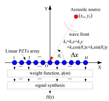
Fig. 2The composite structure imaging method
Applying a weight function to the output signal of each PZT, Eq. (1) can be rewritten as Eq. (2). Eq. (3) is the weight function, in which, is the angle of the weight function:
Transforming the weight function to wavenumber domain, it is represented as Eq. (4):
where is the Dirac function.
It can be seen from Eq. (4) that the weight function can pass through the signal of angle , and reject the signal of the other angles . The filtered synthesis signal of the linear PZTs array can be obtained by combining Eq. (3) and Eq. (2), it is represented as Eq. (5):
The energy of filtered synthesis signal at angle can be calculated by Eq. (6):
where is the signal sampling length.
Then the angle-energy image of acoustic source can be acquired by the spatial filter at each angle. And the damage probability at each angle can be obtained by normalizing the energy.
The excitation signal for damage monitoring is excited by a single frequency signal. But the impact response signal is frequency broadband. Thus, complex Shannon wavelet transform is adopted to extract frequency narrowband signal to fulfill the spatial filter [10].
3. Structural imaging method
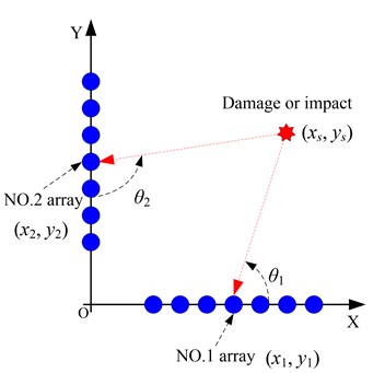
The two linear PZTs arrays are numbered No. 1 and No. 2 array respectively, and the center point are (, ) and (, ), just as shown in Fig. 2. The damage introduces scattering signals and the impact excites the Lamb wave. The angle-damage probability image of damage or impact can be obtained by the spatial filter without using the Lamb wave group velocity.
According to the center point and angle-damage probability image of a linear PZTs array, the damage probability of position (, ) relative to the array can be obtained by Eq. (7). Then the damage or impact angle image of each array can be obtained:
Fig. 3The implementation process of the composite structure imaging method
As shown in Fig. 2, the damage or impact coordinate image can be obtained by fusing the damage or impact angle images of the two linear PZTs arrays. The impact or damage position is calculated by the coordinate probability weighted algorithm which expressed as Eq. (8):
where (, ) is the calculated coordinate, (, ) is a position in the structure, is the damage probability of position (, ).
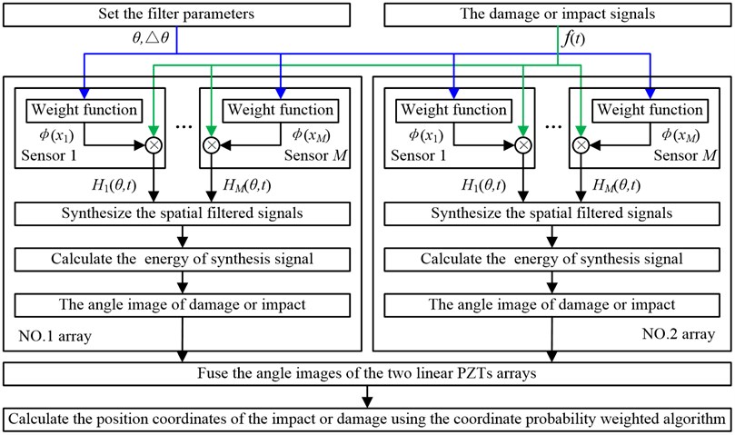
Based on the studies above, the implementation process of the composite structure imaging method based on spatial filter and two linear PZTs arrays without using the Lamb wave group velocity is shown in Fig. 3.
4. Experimental validation
The validation experiment system shown in Figure 4 consists of a carbon fiber composite laminate plate with a dimension of 60 cm×60 cm×0.216 cm (length×width×thickness), an integrated SHM system, two linear PZTs arrays. Each array is constructed by 7 PZTs with a spacing of 1 cm. The method of applying simulated damage on the structure is bonding a mass block on damage position to change the local stiffness of the structure at the bonding area [11], and using impact hammer to generate the impact damage. In the simulated damage experimental, the excitation signal is modulated five-cycle sine burst. The center frequency of the excitation signal is 50 kHz and the amplitude is ±70 V. The sampling rate is 10 MHz and the sampling length is 8000 samples including 1000 pre-samples. The trigger voltage is 5 V. For impact damage experimental, the trigger voltage is 1 V, the sampling rate is 1 MHz, and the sampling length is 5000 samples including 1000 pre-samples. The experimental process of simulated damage: (1) in the health state of the structure, the Lamb wave signals of the two linear PZTs array are acquired as the health reference signals; (2) damage is applied at each position shown in Fig. 4(b) and the corresponding Lamb wave signals of the two linear PZTs array are acquired as the on-line monitoring signals. For impact experiment, the impact is applied at each position shown in Fig. 4(b) and the impact respond signals are acquired respectively.
Fig. 4Experiment of the composite structure imaging method
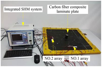
a) Experimental setup
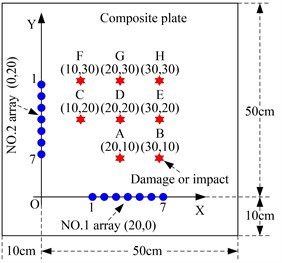
b) Damage and impact position
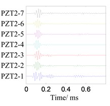
Choose the position C as a typical case to be analyzed first. For damage, the health reference signals and on-line monitoring signals of the two linear PZTs array are shown in Fig. 5 and Fig. 6 respectively.
Fig. 5The health reference signals
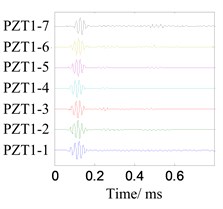
a) No. 1 array
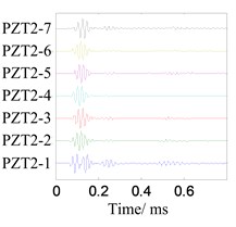
b) No. 2 array
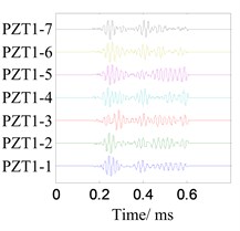
Fig. 6The on-line monitoring signals
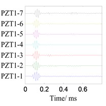
a) No. 1 array
b) No. 2 array
The damage-scattering signals extracted by subtracting with are shown in Fig. 7. The angle searching range is set to [0°, 180°) with the angle resolution is 0.36°. The damage angle images can be obtained by spatial filtering the damage-scattering signals, as shown in Fig. 8. The damage coordinate image can be acquired by fusing the damage angle images of each array, as shown in Fig. 9. The damage position (10.8 cm, 19.7 cm) is calculated by the coordinate probability weighted algorithm, and the damage localization error is 0.85 cm.
Fig. 7The damage-scattering signals
a) No. 1 array
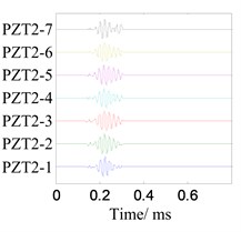
b) No. 2 array
Fig. 8Damage angle images of each array
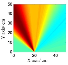
a) No. 1 array
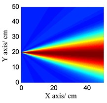
b) No. 2 array
Fig. 9Damage coordinate image
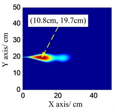
Table 1Location results of the damage and impact without using the Lamb wave group velocity
Position | Actual coordinates / cm | Damage | Impact | ||
Location / cm | Distance error / cm | Location / cm | Distance error / cm | ||
A | (20, 10) | (19.7, 9.4) | 0.67 | (19.5, 10.7) | 0.86 |
B | (30, 10) | (29.3, 9.5) | 0.86 | (30.2, 10.9) | 0.92 |
C | (10, 20) | (10.8, 19.7) | 0.85 | (10.3, 19.7) | 0.42 |
D | (20, 20) | (19.6, 19.1) | 0.98 | (19.4, 19.3) | 0.92 |
E | (30, 20) | (29.5, 19.5) | 0.71 | (29.4, 19.3) | 0.92 |
F | (10, 30) | (10.7, 30.6) | 0.92 | (10.8, 30.5) | 0.94 |
G | (20, 30) | (19.7, 29.9) | 0.32 | (19.5, 29.4) | 0.78 |
H | (30, 30) | (29.3, 29.8) | 0.73 | (29.1, 29.9) | 0.90 |
According to the composite structure imaging process studied above, the imaging and location results of the damage and impact at each position, and the distance errors are listed in Table 1. It indicates that the maximum localization error is no more than 1 cm.
5. Conclusion
This paper proposes a spatial filter and two linear PZTs arrays based composite structure imaging method without using the Lamb wave group velocity, which extends the spatial filter to the application of composite structures. The validation results on a carbon fiber composite laminate plate show that the damage and impact localization errors are less than 1 cm.
References
-
Staszewski W. J., Mahzan S., Traynor R. Health monitoring of aerospace composite structures-Active and passive approach. Composites Science and Technology, Vol. 11, Issue 69, 2009, p. 1678-1685.
-
Liang D., Yuan S. F., Qiu L., David S., Cai J., Liu M. L. Large structural impact localization based on multi-agent system. Journal of Vibroengineering, Vol. 14, Issue 4, 2012, p. 1638-1655.
-
Ostachowicz W., Güemes A. New Trends in Structural Health Monitoring. Springer, New York, 2013.
-
Zhou L., Feng Y. M. A Lamb wave signal processing method for damage diagnosis in the plate structure. Journal of Vibroengineering, Vol. 14, Issue 4, 2012, p. 1607-1615.
-
Qiu L., Liu M. L., Qing X. L., Yuan S. F. A quantitative multi-damage monitoring method for large-scale complex composite. Structural Health Monitoring, Vol. 12, 2013, p. 183-196.
-
Wang L., Yuan F. G. Damage identification in a composite plate using prestack reverse-time migration technique. Structural Health Monitoring, Vol. 4, Issue 3, 2005, p. 195-211.
-
Yu L., Giurgiutiu V. In situ 2-D piezoelectric wafer active sensors arrays for guided wave damage detection. Ultrasonics, Vol. 48, Issue 2, 2008, p. 117-134.
-
Purekar A. S., Pines D. J., Sundararaman S., Adams D. E. Directional piezoelectric phased array filters for detecting damage in isotropic plates. Smart Materials and Structures, Vol. 13, Issue 4, 2004, p. 838.
-
Wang Y., Yuan S. F., Qiu L. Improved wavelet-based spatial filter of damage imaging method on composite structures. Chinese Journal of Aeronautics, Vol. 24, Issue 5, 2011, p. 665-672.
-
Qiu L., Yuan S. F., Zhang X. Y., Wang Y. A time reversal focusing based impact imaging method and its evaluation on complex composite structures. Smart Materials and Structures, Vol. 20, Issue 10, 2011, p. 105014.
-
Sohn H., Park H. W., Law K. H., Farrar C. R. Damage detection in composite plates by using an enhanced time reversal method. Journal of Aerospace Engineering, Vol. 20, Issue 3, 2007, p. 141-151.
About this article

This work is supported by the National Natural Science Foundation of China (No. 51205189), the National Science Fund for Distinguished Young Scholars (No. 51225502), the China Postdoctoral Science Foundation (No. 2012M510134), the Research Fund for the Doctoral Program of Higher Education of China (No. 20123218120007), the Priority Academic Program Development of Jiangsu Higher Education Institutions and the Qing Lan Project.
