Abstract
The kinematics concurrent vibratory rolling screw system used in rolling screw screen that is used for sieving materials of fine and very fine grain was examined. The conducted experiments regarded the measurement of the torsional vibration sieve column ( and axis) and the measurement of the vertical vibration of the column (-axis).
1. Introduction
Theoretical foundations of the rolling-screw system were developed by the Russian physicists last century. On the basis of that principle a screen was built which is driven by two motor vibrators working in mutual concurrent self-synchronization. The conversion of the amplitude depending on the weight of the device is effected by the alignment of working moments [1-5]:
Motor vibrations axes are inclined towards the horizontal surface of the screen at degree. The vibratory motion is composed of: vertical vibratory motion (amplitude ) and torsional vibrations (angular amplitude ) [6-11].
Fig. 1Dynamic diagram of rolling – screw screen operations driven by two self – synchronized motor vibrators [6]
![Dynamic diagram of rolling – screw screen operations driven by two self – synchronized motor vibrators [6]](https://static-01.extrica.com/articles/15459/15459-img1.jpg)
The irregularities obtained by Sterling (model 2) are used for the calculation of the component of vertical vibration () and component of horizontal vibration () (Fig. 1) (model 2). The solutions for the rolling screw system are given by I. Blechman. The solutions regard two twin motor vibrators fastened to the cushioned solid [6].
Sterling’s theorem:
Synchronous vibrations correspond to the screw vibrations. They are described by the equation of the movement:
– Vertical component:
– Horizontal component:
hence:
– The amplitude of horizontal vibration of the system:
– Angular horizontal amplitude:
where: – inclination angle of the motor vibrators in respect of the horizon:
moment of inertia of the cylinder and – angular velocity of the frequency, (s-1):
exciting force of the vibration, (N) and - linear velocity in a circular motion, (m·s-1); – distance of gravity centre of the counterweight from the motion shaft, (mm); 450 mm – distance of motor vibrators fastening from the sieve column; – vibration amplitude in motor vibrators fastening axis, (mm); – vibration amplitude perpendicular to axis, (mm); – vibration vertical amplitude, (mm); torsional vibration amplitude on the horizontal surface, (mm); – distance of gravity centre of sieve column from the motor vibrators fastening, (mm); – distance of gravity centre of sieve column from the sieve column base, (mm); 0.56 m – sieve column diameter, – mass, (kg); – frequency, (s-1); – acceleration of the system – measurement, (m·s-2).
For the test rolling screw screen:
– exciting force of the vibration:
– exciting force for the adjustable motor vibrator:
Constant in the equation:
Constant of the equation:
hence, vertical vibration amplitude of the system, (mm):
Angular horizontal amplitude:
For the calculation of the kinematic operating system, according to the above equations, it is necessary to specify the angle position of the motor vibrators and the size of the force causing vibrations. The undertaken work and the determined dependency allow for the optimization of the screening process in a rolling screw screen [1, 2, 6, 7, 12, 13].
2. The aim of the study
The aim of the study was to define the amplitude of horizontal and vertical vibrations.
The scope of changes of the vibrations amplitude study for:
– Six forces exciting the vibrations: 100 %, 97 %, 90 %, 80 %, 70 %, 50 % maximum force of motor vibrators equals 4060 N and for the mass of the device of 170 kg;
– Inclination angles of the motor vibrators providing the circular motion of the material: 0, 10, 20, 30, 40, 45, 50, 60, 70, 80, 90° [3-5].
3. Materials and methods
The amplitude measurements were made of horizontal and vertical vibrations of the screen driven by two motor vibrators which are three phase motors with unbalanced weight at both ends of the shaft.
VIBRA Pol type BM 200/15 motor vibrators were used, revolutions 1500 min-1, voltage 380 V, current 0,45 A, power 180 W, the maximum exciting power 2∙2030 N, weight 11 kg. The coefficients determined the kinematic eguations , .
The amplitude measurements were made for:
– Six forces exciting the vibrations: 100 %, 97 %, 90 %, 80 %, 70 %, 50 % the maximum force of motor vibrators equals 4060 N and for the mass of the device of 170 kg;
– Inclination angle of the vibrators providing the circle motion of the material: 0, 10, 20, 30, 40, 45, 50, 60, 70, 80, 90°.
The amplitude was recorded with B&K accelerometer. Piezoelectric sensor system PULSE enabled the measurement of the column acceleration.
The measurements results and calculations are presented in the graphs below.
4. Results and discussion
4.1. The measurement of horizontal vibrations of the amplitude
The amplitude of horizontal vibrations of the system is directly proportional to the force exciting the vibration and it depends on the sin of the angle of motor vibrators position Eq. (13). The sequence of calculated function coincides with the measurements that indicates a good match of obtained kinematic equations.
Fig. 2XY amplitude measurements of the sin angle of motor vibrators position
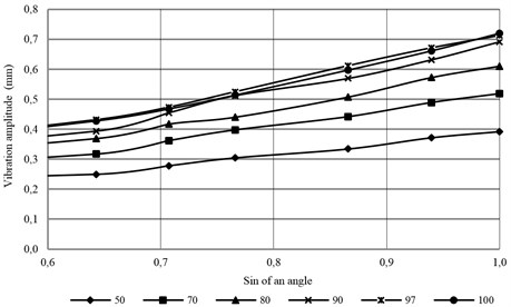
Fig. 3The dependence of the reduced horizontal component XY on the sin of an angle of motor vibrators set-up
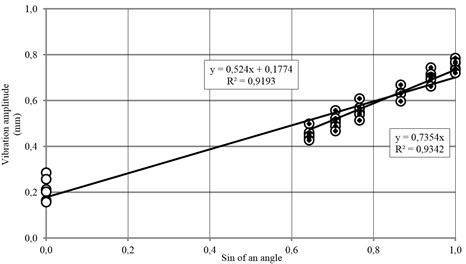
Fig. 4Torsional amplitude measurement Z axis of cos of an angle of motor vibrators position
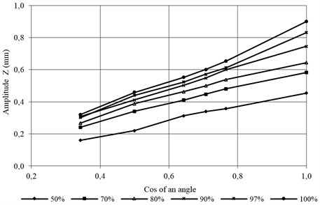
Reduced torsional vibration equation – the horizontal motion of amplitude describes the dependence:
For an angle of 0° – for the vertical motor vibrators position, spring suspension made of 12 springs has an influence on the torsional vibration system.
4.2. Vertical vibration measurement
The dependence of vertical vibration amplitude for the vibration motion of amplitude, on the force exciting the vibrations and the angle of motor vibrators position is described by the equation:
Vertical vibration amplitude is proportional to the force exciting the vibrations and to the cos of an angle of motor vibrators position Eq. (13) for changes of an angle from 40o to 90o:
Fig. 5The dependence of vertical component Z reduced from cos of an angle of motor vibrators position
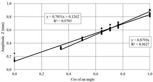
For an angle 90° – for the horizontal position of motor vibrators, the spring suspension, consisting of 12 vibration damping springs, has an inhibitory influence on vertical vibration.
Fig. 6The dependence of vertical and horizontal vibrations amplitude on an angle of motor vibrators position angle
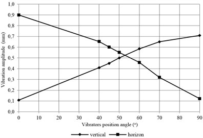
The values of the horizontal and vertical vibrations equate to an inclination angle of motor vibrators of approx. 50°. In this range, the screen shows the highest efficiency.
5. Conclusions
The already made measurements led to the following conclusions:
1. The value of used force % and the angle of inclination of the side motor vibrators have an influence on the dynamics of the screen operation of 170 kg weight and the maximum vibration exciting force which equals 4060 N:
– The tested screen should have maximum efficiency with the maximum exciting force, for which an angle of motor vibrators is comprised of 40° to 50°, and preferably 45° (Fig. 6). These results are confirmed in the research process in our laboratory within the frame of PhD thesis.
2. On the basis of the research the equations describing the amplitude in vibration motion were determined, depending on the inclination angle of motor vibrators and the force exciting the vibrations:
– The dependence of torsional vibrations – horizontal motion, of an angular amplitude describes the equation:
For an angle of 0° – for vertical position of the motor vibrators, the damping of the suspension spring has an effect on the torsional vibrations :
– The dependence of vertical vibrations of the amplitude on the force exciting vibrations and the angle of motor vibrators position is described by the equation:
For an angle of 90° – for vertical position of motor vibrators, the damping of the suspension spring has an effect on the torsional vibrations :
4. The values of the horizontal and vertical vibrations will equate when the inclination angle of the motor vibrators is about 50°. In this range the screen shows the highest efficiency.
5. The achieved results allow to submit optimal settings for the screen operation and the maximum use of the productive potential of the device.
References
-
Banaszewski T. Screens. Śląsk Publishe, 1990, (in Polish).
-
Barskij Ł., Płaksin I. Optimization criteria of separate processes. Moskwa Nauka, 1967, (in Russian).
-
Poćwiardowski W., Kaniewska J. The influence of the angle of motor vibrators on the amplitude of vibration of the screen. Agricultural Engineering, p. 287-297, (in Polish).
-
Poćwiardowski W., Wodziński P., Kaniewska J. Investigation of the rolling screen. AGH Journal of Mining and Geoengineering, Vol. 36, Issue 4, 2012, p. 143-157.
-
Poćwiardowski W., Wodziński P., Kaniewska J. The concept of the scientific standpoint of the rolling-screw screen. Partial automation of the screening process. Physicochemical Problems of Mineral Processing, Vol. 50, Issue 1, 2014, p. 97-105.
-
Blechman I. Synchronization of dynamic systems. Moskwa Nauka, 1971, (in Russian).
-
Dyr T., Wodziński P. Model practice velocity on a vibrating surface. Physicochemical Problems of Mineral Processing, Vol. 36, 2002, p. 147-157.
-
Patent: CN202993777U, Coin vibration dryer.
-
Patent: US4785551A, Metchod for drying confection pieces.
-
Patent: JP10160346A2, Dryer.
-
Patent: CN2662167Y, Intensive transmission vibration type powder material dryer.
-
Cieplok G., Michalczyk J. The Digital model of vibrating screen. Engineering Modeling, Vol. 32, 2006, p. 381-388, (in Polish).
-
Dietrych J. The theory and the construction of the screen. WGH, Katowice, 1962, (in Polish).
-
Sztaba K. Sieving. Publisher Śląsk, Katowice, 1993, (in Polish).
-
Wodziński P. Sieving and screens. Monograph 907, Publisher Institute of Technology, Lodz, 1997, (in Polish).
