Abstract
This text describes the development of an efficient approach to the analysis of the dynamics of a rotor with a structure that contains active elements. Since the Ansys software, according to our experience, has limitations in the area of rotor dynamics and due to the fact that the use of control algorithms is difficult to implement in Ansys, a new analysis approach to the study of smart rotors has been created and verified. After the generation of the geometry and building the model in Ansys, the finite-element model matrices are imported into Matlab. The space state model is created next so that the reliable control software available in Matlab can be used. The verification of this analysis method has been done by comparison with the results obtained using an analytical model of a smart Jeffcott rotor with and without control.
1. Introduction
The dynamics of rotating systems display many phenomena and features that are non-intuitive and not easy to understand. For the same geometry and the rotational speed, regardless of the external loads, the motion of the rotor can be stable or unstable subject to a small change in the effective internal or external damping coefficients. This high sensitivity to the damping conditions is characteristic of the supercritical range of rotor rotational speeds. Self-induced vibrations can be excited in such systems due only to damping and the rotation of the system. For some time now, the authors have been studying a method of actively changing the effective damping coefficients of a smart rotor by active control with piezoelectric patches used as sensors and actuators, bonded on the surface of the shaft.
The present work is focused on an efficient approach to the simulation of smart rotors and the synthesis of their control algorithms. The structure being considered is a complicated dynamical system that needs to be modelled very carefully. Since the possibilities of finite element codes are often not fully adequate in this respect, the authors have decided to create an environment that combines the capabilities of finite element modelling in the Ansys commercial software and Matlab, in order to simulate efficiently the dynamic response of a smart rotor and to perform simulation studies of its active control. The accuracy of the proposed method has been verified on a simple two degree-of-freedom analytical model.
2. Capabilities of Ansys in rotordynamics
Version 12.1 of Ansys has been used in this assessment. The dynamics of rotors can be analysed in Ansys in either the stationary or rotational reference frame. The major restriction of the stationary reference frame is the requirement of the axial symmetry of the geometry used [1]. Although the damping and gyroscopic effects are taken into account in the equations of motion in this frame, this reference frame cannot be used to properly simulate a smart rotor, due to the presence of piezoelectric parts of the structure. In the analyses done in the stationary reference frame the piezoelectric elements would always act in the global (nonrotating) directions, in other words these elements would remain stationary and would not rotate with the shaft.
Therefore, to simulate correctly the interaction between the piezoelectric patches and the shaft it is necessary to use the rotating reference frame. However, the equations of motion in this frame do not include all the necessary terms, and hence the results should be treated with care. In an earlier paper [2], all limitations of the rotating reference frame in Ansys were considered in detail. In this reference frame the term that describes the gyroscopic effect is missing and there is no circulatory matrix that results from external damping [3]. These limitations have led the authors to consider a way of importing the FEM matrices into MATLAB, in order to be able to modify the equations.
3. Ansys FEM model of a smart rotor and its importing into Matlab
The model of the smart rotor consists of a beam with a square cross-section and a lumped mass attached in the middle of its length (Fig. 1(a)). The mass has an eccentricity relative to the rotation axis, which results in an unbalance force. The gyroscopic effects are negligible for such a geometry and they are not included in the analysis. It is assumed that the structure rotates at a constant rotational speed, and that both ends of the rod are fixed. Piezoelectric elements are bonded near the ends of the shaft; there are two pairs of collocated sensors and actuators at each end. Piezoelectric patches have the poling direction perpendicular to their attachment surface. This structure of a smart rotor has been modelled using the finite-element method, and its FEM model is shown in Fig. 1(b). Independently, a simple analytical model of such a Jeffcott rotor with piezoelectric patches has been described in Ref. [4]. This model will be used for verification purposes.
Fig. 1The model of the smart rotor
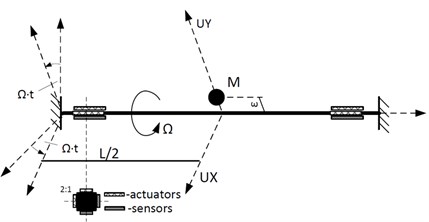
a) Schematic drawing of the structure
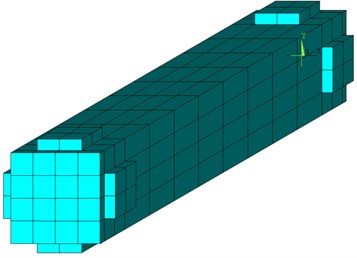
b) Finite element model
It is important to note that the number of elements affects the time needed to import the model into Matlab and to perform the subsequent simulations. Therefore, the generated mesh has been created with emphasis on the fact that it would not be too fine and the number of all DOF remains relatively small.
After the meshing of geometry, the boundary conditions have been imposed and the fixed degrees of freedom have been removed from the matrices formed. In order to model the presence of the electrodes on the surfaces of piezoelectric elements the voltage DOFs on appropriate nodes have been coupled, which further reduces the size of the problem. The mass-, stiffness- and the velocity-related (including the damping and Coriolis effects) matrix can be created in the Harwell-Boeing format in Ansys using the “hbmat” command. The latter of these matrices reduces to the Coriolis matrix if one sets damping to be equal to zero. In such a way the Coriolis matrix can be retrieved. It is to be emphasized that the Coriolis and the spin-softening matrices depend on the rotational speed.
In the next step all matrices have been imported into Matlab. Since the Harwell-Boeing format designed to store information for sparse matrices in Ansys is not recognized in Matlab, an external source code has been used to change the format [5]. The elements of the mass matrix that correspond to the electrostatic potential DOFs are all equal to zero, and the mass matrix is singular and does not have a matrix inverse. Therefore, in the first step it is important to remove the electrostatic potential in the manner discussed in Ref. [6]. Then, the magnitude of the interaction of the piezoelectric actuators and the charge generated on the sensors can be calculated using the corresponding elements of the stiffness matrix responsible for the electromechanical coupling (more details on the finite element formulation of the piezoelectric vibration problem with the definition of the respective matrices can be found in Ref. [6]). In this calculation, explicit use is made of the fact that the sensors have been equipped with charge amplifiers, and therefore the voltage across the sensors is equal to zero.
The damping has been modelled as Rayleigh’s damping (, where is the stiffness matrix in the absence of rotation). A consistent circulatory matrix corresponding to the assumed damping model has also been determined and used (for details see [3]). As is customary in the analysis of control systems, the final equations have been written in the state-space form.
4. Verification results
In order to verify the proposed approach, the results obtained using the approach discussed above will be compared with analytical solutions. The model of Section 3 corresponds to a standard Jeffcott rotor and it can be described analytically by a set of two differential equations, as has been discussed, e.g., in Ref. [3].
At time zero the structure rotates at a constant rotational speed and it is assumed that the rotor is not deformed, and all its points have zero velocity in the rotating frame at this initial time. The only loads acting on the structure are the inertial forces, corresponding to the eccentricity of the lumped mass. The gravity forces have been omitted.
Since the aim of the simulations is to test the correctness of the modelling of damping, artificial values of the parameters of Rayleigh’s model have been used, so as to bring out the effects. Fig. 2(a) presents the displacements of the centre of the rotor as a function of time, obtained using the analytical model. This model is fully consistent and it has all the matrices, including the circulatory matrix. Fig. 2(b) shows the same results obtained in Ansys in a rotational frame, as well as using the modified approach described above. The following values of parameters have been used: 100 rad/s, 10 1/s and 0 s. Comparing the results in Fig. 2(b) with Fig. 2(a) one can observe that the results obtained in the Ansys commercial program diverge from the analytical results. This is due to the absence of the circulatory matrix in the Ansys model. This inaccuracy has been removed in the model created in Matlab using the matrices imported from Ansys, as can be seen from the plots.
Fig. 2Diplacements of centre of the shaft
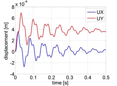
a) Jeffcott model with Rayleigh damping (10 1/s, 0 s)
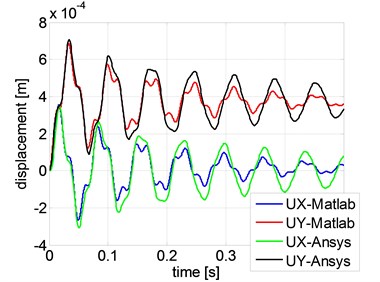
b) FEM models with Rayleigh damping (10 1/s, 0 s
Apart from the uncontrolled case discussed above, the case of a smart rotor with direct velocity feedback control ([7]) has been studied. In order to implement the control algorithm, Matlab time-continuous space-state model has been converted to a discrete-time model with sample time 0.0005 s. Since this control approach requires the calculation of a time derivative, a low-pass filter has been applied to the measured signals, in order to reduce the influence of the high-frequency modes (spillover effect) and numerical noise.
Fig. 3(a) shows the response of a shaft without active control, rotating at velocity 750 rad/s. For the parameters used shaft instability takes place, caused by self-excited vibrations. The shaft can be made stable by applying active control, as is shown in Fig. 3(b). The same results for the smart rotor with control have been obtained using the analytical approach discussed in the earlier paper [4], where more details can be found.
Fig. 3Diplacements of centre of the shaft for FEM model solved in Matlab
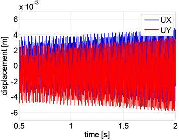
a) Without control: 750 , 0.4705, 1.0058e-005
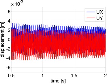
b) With an implemented control algorithm: 750 , 0.4705, 1.0058e-005
5. Conclusions
The approach to the study of smart rotating systems proposed by the authors combines the advantages of the Ansys and Matlab software. It creates a powerful tool that can be especially useful in the analysis of controlled structures. An arbitrary geometry can be easily created in Ansys and then used in Matlab, where there are many tools available for the design of control systems. The effectiveness is limited at the present stage by the number of DOFs, but it is planned to use the model-order reduction procedures to analyse and simulate complex system within acceptable times.
References
-
Ansys V12.1 Mechanical APDL Help.
-
Cupiał P., Kozioł M. Finite element analysis of a jeffcott rotor with piezoelectric patch sensors. Modelowanie Inżynierskie, Vol. 43, 2013, (in Polish).
-
Genta G. Dynamics of Rotating Systems. Springer, New York, 2005.
-
Cupiał P., Kozioł M. The Analysis of a smart jeffcott rotor with direct velocity feedback control in the supercritical range. Journal of Low Frequency Noise, Vibration and Active Control, Vol. 32, Issue 3, 2013.
-
http://people.sc.fsu.edu/~jburkardt/m_src/hb_to_msm/hb_to_msm.html.
-
Allik H., Hughes T. J. R. Finite element method for piezoelectric vibration. International Journal for Numerical Methods in Engineering, Vol. 2, Issue 2, 1970.
-
Preumont A. Vibration Control of Active Structures. 2nd Edition, Kluwer Academic Publishers, Amsterdam, 2002.
About this article

The second author would like to acknowledge the support of this research by the Dean of the Faculty of Mechanical Engineering and Robotics of AGH UST (Grant No. 15.11.130.968/14).
