Abstract
A flip-flow screen with crankshaft-link structure (FFSCLS) is an effective solution for screening of high-water and fine materials due to its good performance. The dynamical characteristics largely affects the screen performance and the processing capacity of the FFSCLS. In this paper, a dynamic model governing the dynamical characteristics of the FFSCLS was proposed. In addition, the motion trajectory and vibration data of the FFSCLS were investigated by vibration experimental technology. The results show that the experiment results can be fully described by the dynamic model whit the maximum deviation was within 6.26 %. Moreover, the mass ratio between outer box and inner box determined the dynamical characteristics of the flip-flow screen, and these parameters should be optimized. This work can provide useful references for efficient operation and optimal design for the flip-flow screen.
Highlights
- The dynamical model of a flip-flow screen with crankshaft-link structure was proposed.
- The vibrations of the FFSCLS were examined by experimental test and compared with theoretical calculation.
- The effects of key parameters on dynamics of the FFSCLS were analyzed.
1. Introduction
It is known that screens can be considered as the main equipment in mining industry [1, 2]. Dry screening of viscous and fine-grained minerals plays an indispensable role in processing coal ore, and iron or gold deposited rocks, etc. [3-7]. However, conventional screening equipment (linear vibrating or circular vibrating screens) usually encounter many problems, such as blocking and low efficiency when dealing with moist materials [8-11]. The flip-flow screen with elastic screen surface has been widely used for screening fine-grained minerals due to its good performance [12, 13]. To achieve the best screening performance of flip-flow screen with simultaneously increasing lifetime, a better understanding of its dynamics is necessary, thereby optimizing structural design [14].
Till date, many researchers investigated and analyzed the dynamic response and the operation mechanism of the flip-flow screen. Increasing the relative amplitude and avoiding undesirable resonances of the inner and outer boxes can be realized to improve the screening performance [15]. The dynamic response of the flip-flow screen largely affects its screening efficiency and processing capacity and the dynamic response curves were measured and analyzed under different operating conditions [16, 17]. Kinematics of the screen boxes and the surface of the flip-flow screen were investigated using acceleration sensor and laser displacement sensor, the results showed that screening experiments obtained excellent screening efficiency [18]. The dynamic characteristics and vibration of a flip-flow screen have been investigated; the results showed that this kind of screen was efficient even dealing with moist fine coal [19-21].
The vibration of the screen boxes can be decomposed into several components along different directions in the coordinate system. Then, dynamic characteristics of the screen boxes are explored by solving vibration differential equations, which are established based on the vibration theory [22]. Considering degrees of freedom in the translation and rotation, 1- degree of freedom (DOF) [15], 2-DOF [23], spatial 3-DOF model [24, 25] and coupled 3-DOF [26, 27] are adopted. From the standpoint of flip-flow screen applicability, the 1-DOF model is the most appropriate in dynamic analyses.
In our current study, a dynamical model of a flip-flow screen with crank-link structure was established. The time evolution of kinematic characteristics and spatial trajectories of the FFSCLS were investigated using vibration testing experiments. Besides, the mass ratio of outer box to the inner box on the dynamical characteristics of the flip-flow screen were analyzed parametrically. The results help in clarifying the kinematic characteristics and mechanical response of the FFSCLS, which provide technical and theoretical support for industrial applications and optimal design.
2. Mathematical model
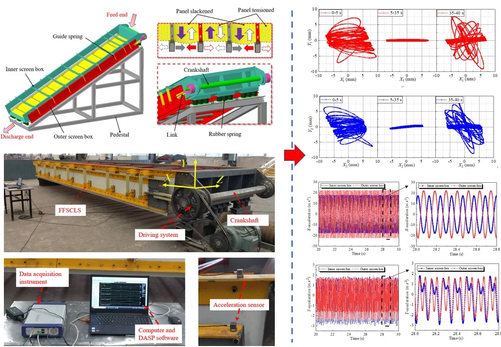
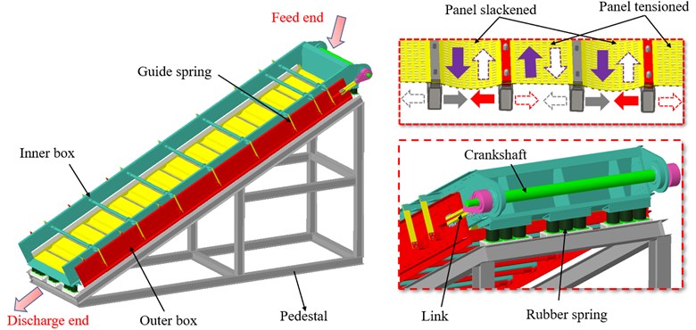
The investigated of the FFSCLS produced by Zhen Yuan Science Technology Co., Ltd in Henan China is shown as Fig. 1. The inner box is supported under the pedestal by cylindrical rubber springs. by the guiding springs connect the outer and inner boxes. The screen surface with 8.82 m length and 2.2 m width is composed of 28 polyurethane screen panels. The two ends of one screen panel are installed on the crossbeam of inner box and adjacent outer box. The crankshaft is installed at the feed end of the inner box and rotated by a driving motor. The link connects the crankshaft and the outer box. Moreover, the rotation of the crankshaft provides a simple harmonic vibration with the inner and outer screen frames, which results in periodical slack and stretch motions of the elastic screen panel. Then, under the projectile behavior of the elastic screen surface, particles can achieve a high ejection acceleration of 30-50 g [28]. Even plugging particles can easily pass through the screen surface, ensuring high screening capability and efficiency [29].
Fig. 1The mechanical structure of the FFSCLS
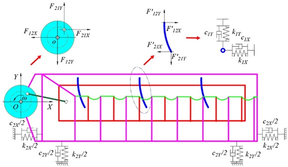
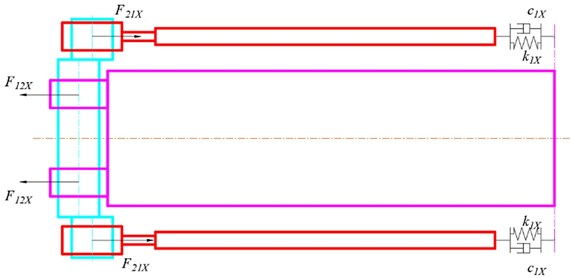
Vibration characteristics including displacement, velocity, and acceleration can be obtained by dynamical model. The dynamical model of the FFSCLS was established as shown in Fig. 2. The dynamic equation of the vibration system can be established as Eq. (1) [30]. The displacement of the outer box screen box and the displacement of the inner box along -direction can be calculated according to the Eq. (2). Based on Eqs. (1-2), the displacement, velocity, and acceleration of the outer box (, , ) can be obtained by Eq. (3), the displacement, velocity, and acceleration of the inner box (, , ) can be obtained by Eq. (4):
where, and are the mass of the outer and inner boxes; and are the rotational speed and eccentricity of the crankshaft; and are the damping and equivalent stiffness coefficients of the cylindrical rubber springs, respectively.
Fig. 2Dynamical model of the FFSCLS
a)
b)
3. Results and discussion
3.1. Experiment set up
Main parameters of the FFSCLS are shown in Table 1. The vibration behavior of the FFSCLS is closely related to its screening performance. The vibration testing technology was adopted to analyze the dynamical characteristics of the outer and inner boxes. Fig. 3 shows the field layout of the experimental test and analysis system, including FFSCLS, vibration test and signal analysis system.
Fig. 3Field layout of the experiment and analysis system
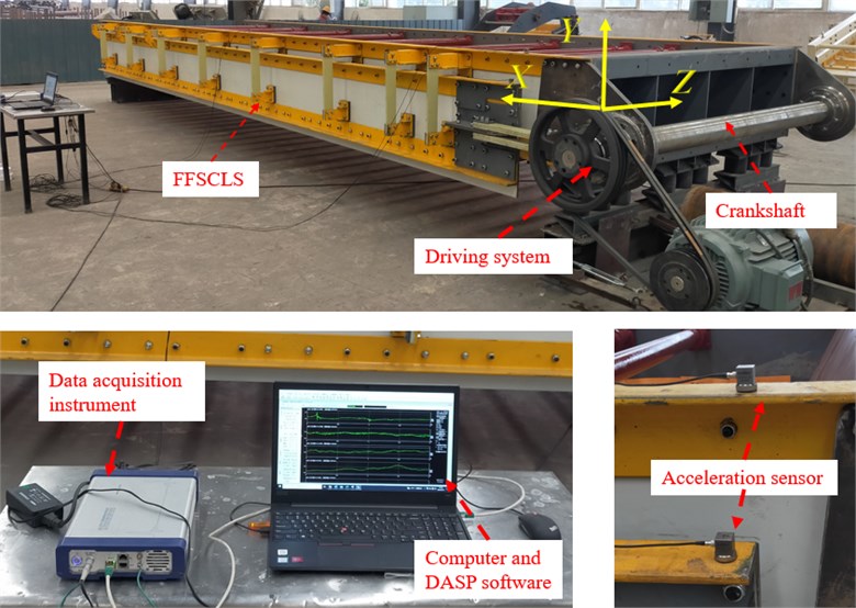
The rated power of the driving motor is 37 kW, and the rated rotational speed is 1480 r∙min-1 (660 V, 50 Hz). The pulley reduction ratio 2.68. Thus, the rotational speed of crankshaft was 550 r∙min-1 (57.6 rad∙s-1). The vibration test and signal analysis system consist of INV9832 ICP three directions acceleration sensors, a 16 channels data acquisition instrument, and DASP software installed in a computer. Acceleration sensors are absorbed on the inner and outer boxes by magnetic seats. The -direction of the acceleration sensor was parallel to the material flow, and the -direction was perpendicular to the -direction.
Table 1Parameters of the FFSCLS
Item | Value |
(mm) | 12 |
(N∙mm-1) | 1670 |
(N∙mm-1) | 6635 |
Damping ratio | 0.01 |
(kg) | 3500 |
(kg) | 5300 |
Before each experiment, the parameters of DASP software were set. Then enable the sampling mode of the DASP software and start the drive motor. Since the vibration of the screen is stable, keep recording for a period of time, then turn off the motor. Wait until the vibration of the screen is completely stopped, shut down the signal collection. Finally, the signal was recorded and the dynamical parameters can be measured.
3.2. Dynamic characteristics of the FFSCLS
The dynamic characteristics of the outer and inner boxes were analyzed after the vibration experiment. Fig. 4 demonstrates the time-domain characteristic curves of displacement signals about outer and inner boxes. In general, the displacement curves can be divided into three stages: initial stage (0-5 s), stable stage (5-35 s) and stop stage (35-40 s). At the initial stage, the displacement amplitudes of the outer and inner boxes in the -direction gradually increase with the max value of 8.52 and 9.49 mm respectively and finally stabilize. The displacement amplitudes in the direction increases rapidly at first and then decreases slowly with the peak value of 6.50 and 7.19 mm, respectively. During the stop stage, the displacement amplitude of the inner and outer boxes in the -direction decreases tardily, while the displacement amplitudes in the -direction increases and then decreases.
Fig. 4Displacement signals of the outer and inner boxes
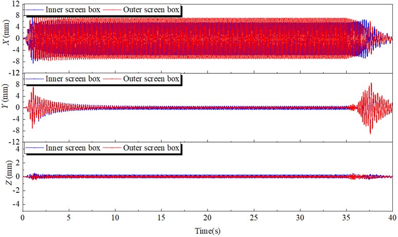
Fig. 5 demonstrates the displacement signals under the steady stage. The displacement signals of the inner and outer boxes are shown as standard sine waves. The motion directions of the outer box and the inner box in the -direction are opposite for the phase difference between the two waveforms is 180 degrees. The displacement amplitudes of the outer and inner box along -direction are 6.93 and 5.42 mm, respectively. The displacement amplitudes of the outer and the inner boxes along -direction are 0.32 and 0.52 mm, both very small, the displacement amplitudes along -direction are even smaller than along -direction. Therefore, compared to the value along the -direction, the displacements along - and - direction both can be neglected.
Fig. 5Displacements under the steady working condition
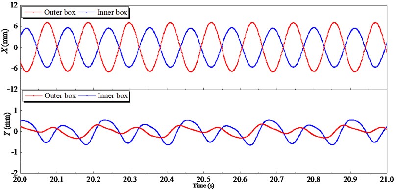
Fig. 6Lissajous displacement patterns of the outer and inner boxes
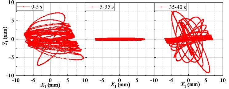
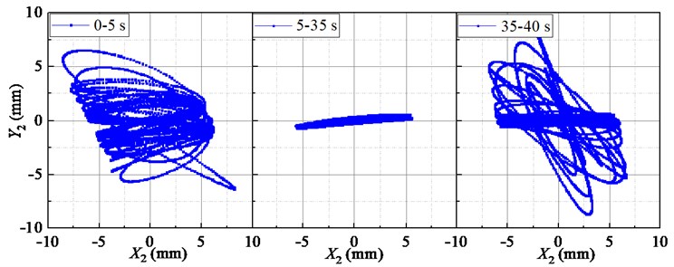
Fig. 6 shows the displacements Lissajous figure of the outer and inner boxes. The trajectories of the outer and inner boxes are messy at the initial stage (0-5 s) and stop stage (35-40 s). The trajectories look like a straight line at stable stage (5-35 s). In addition, the outer box and the inner box are oscillating around their respective centers, and the swing amplitude of the outer box is greater than that of the inner box.
In addition, because the screen box does high frequency vibration, so the acceleration is regarded as an important indicator to measure its vibration intensity. Fig. 7 shows the acceleration signals of the outer and inner boxes along and -directions during stable state. Like the displacement curves, the acceleration curves of the inner and outer boxes are also 180° out of phase in the direction. Moreover, the -direction acceleration amplitude of the outer box is close to 22.20 m∙s-2, while the acceleration amplitude of inner box is 17.59 m∙s-2. The -direction acceleration of the outer and inner boxes show a similar trend, both acceleration amplitudes are less than 2.72 m∙s-2. Therefore, the rationality of 1-DOF model is further proved.
Vibration parameters of the flip-flow screen obtained by the experimental and theoretical results under the steady working condition are listed in Table 2. The experimental results are in good agreement with the theoretical results. The relative error about the velocity amplitude of the inner box is the largest with the value of 6.26 %. Furthermore, less than 6.05 % of the rest of relative errors between the calculations and experiments are observed. Hence, the accuracy of the dynamical model about the FFSCLS at steady state is proved.
Fig. 7Acceleration signals of the outer and inner boxes
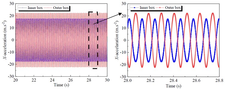
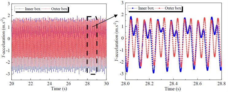
Table 2Theoretical and experimental results of the vibration parameters
Item | X1 (mm) | (mm∙s-1) | (m∙s2) | X2 (mm) | (mm∙s-1) | (m∙s2) |
Experimental results | 6.95 | 371.4 | 22.20 | 5.43 | 291.05 | 17.59 |
Theoretical results | 6.93 | 396.20 | 23.0 | 5.12 | 289.10 | 16.80 |
Error / % | 0.29 | –6.26 | 3.48 | 6.05 | 0.67 | 4.70 |
3.3. Vibration behaviors with different mass ratio between inner and outer box
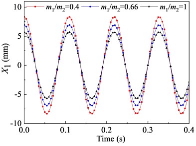
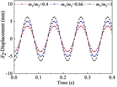
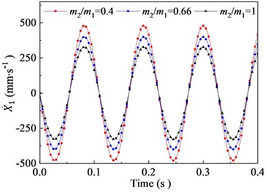
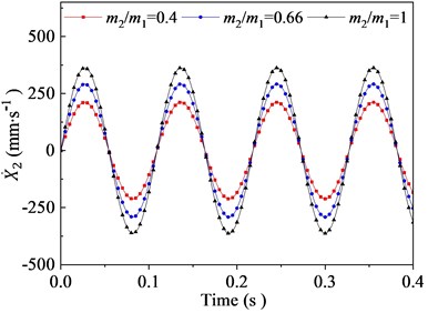
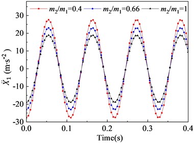
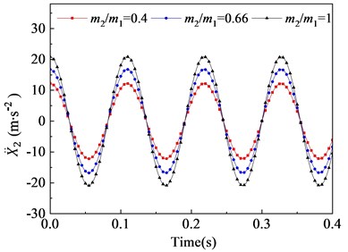
In this section, the effects of the mass ratio between inner and outer box on the vibration characteristic of the flip-flow screen are investigated parametrically. Parameters discussed here are listed in Table 3. The crankshaft eccentricity is 12 mm. The rotational speed of the crankshaft is 550 r∙min-1 (57.6 rad∙s-1). The stiffness coefficients of the rubber spring is 1.67E+06 N∙m-1. The mass of the inner box is 5300 kg. Through the dynamic model, it can be concluded that the vibration characteristics of the inner and outer box in the direction are closely related to their mass ratio. To research the effect of mass ratio (outer box mass to inner box mass) on the FFSCLS vibration performance of the flip-flow screen, the mass ratio of 0.5, 0.66 and 1 were taken for discussion respectively. The changing regular of the displacements, velocities, and accelerations about the outer box (, , ) and inner box (, , ) with the mass ratio of 0.4, 0.66 and 1 are shown in Fig. 8. It can be seen that, the amplitude of displacement (Fig. 8(a)), the amplitude of velocity (Fig. 8(c)) and the amplitude of acceleration (Fig. 8(d)) decrease with the increase of . To the contrary, the amplitude of displacement (Fig. 8(b)), the amplitude of velocity (Fig. 8(d)) and the amplitude of acceleration (Fig. 8(e)) all increase with the increase of .
Fig. 8(a) shows that the curve of displacement about the outer box demonstrates cosine variation law during the process of vibration. When the mass ration of 0.4, the displacement amplitude is 8.32 mm. The displacement amplitude of the outer box decreases from 8.32 mm to 6.94 mm when the mass ration increases from 0.4 to 0.66. Then, when further increases to 1, a larger decrease in the displacement amplitude of is observed, whose value is 5.70 mm. Fig. 8(b) is the displacement curve of the inner box . The displacement amplitudes of the inner box increases from 3.68 mm to 5.06 mm when mass ration increases from 0.4 to 0.66. Similarly, when further increases to 1, the value of is about 6.23 mm. Under the same mass ration, the sum of and is always equal to the value of eccentricity e.
Table 3Parameters used in section 3.3
Item | Value | ||
Eccentricity of the crankshaft, (mm) | 12 | ||
Rotational speed of the crankshaft, (r∙min-1) | 550 | ||
Stiffness coefficients of the rubber spring, (N∙mm-1) | 1670 | ||
Damping ratio, / | 0.01 | ||
Mass of the inner box, (kg) | 5300 | ||
Mass ratio, | 0.4 | 0.66 | 1 |
The velocities curves of the outer and inner boxes are shown as Fig. 8(c) and 8(d). When mass ration increases from 0.4 to 0.66, the outer box velocity amplitude decreases from 479.3 mm∙s-1 to 399.7 mm∙s-1, and then decreases relatively rapidly to 328.3 mm∙s-1 when further increases to 1. On the contrary, the inner box velocity amplitudes increases from 211.8 mm∙s-1 to 362.8 mm∙s-1 when increases from 0.4 to 1. Under the same mass ration, the sum of t and is always equal to 691.1 mm∙s-1, which equal to . The accelerations curve of the outer and inner boxes are shown as Fig. 8(e) and 8(f). When the mass ration increases from 0.4 to 1, the outer box acceleration amplitudes decrease from 27.6 m∙s-2 to 18.9 m∙s-2 while the inner box acceleration amplitudes increase from 12.2 m∙s-2 to 20.9 m∙s-2, respectively. Under the same mass ration, the sum of and is always equal to with the value of 39.8 m∙s-2.
It can be seen from the trend of the curve that, when the mass of inner box remains unchanged, increasing the mass of outer box will make the vibration amplitudes of the two screen boxes tend to be the same. Thus increase the mass ratio has a beneficial effect on the smooth operation of the screening machine. However, excessive increase of will also result in excessive compression force and shear force on the supporting springs and overweight of the whole screen. Therefore, optimal mass ratio should be chosen within a reasonable range.
Fig. 8Vibration behaviors of the outer and inner boxes with different mass ratio: a), b) displacement X1, X2; c), d) velocity X1˙, X˙2; e), f) acceleration X¨1, X¨2
a)
b)
c)
d)
e)
f)
4. Conclusions
1) The vibration characteristics of the flip-flow screen with crank-link structure (FFSCLS) were studied through theoretical method and experimental test. Based on the established FFSCLS dynamic theory model, the dynamic characteristics and vibration behavior of inner and outer boxes can be obtained. The maximum deviation between the theoretical and the experimental results was within 6.26 %.
2) The experimental results indicated that the vibration directions Including displacement, velocity and acceleration of the outer and the inner boxes are opposite along -direction. The trajectories about the outer and inner boxes approximates straight line. The vibration of the outer box increases while that of the inner box decreases with the increase of the mass ration .
References
-
T. Bento Linhares and C. Bruno Santos Vimieiro, “Analysis of the dynamic forces acting on a vibrating screen and its support structure using a scale model,” Measurement, Vol. 176, p. 109179, May 2021, https://doi.org/10.1016/j.measurement.2021.109179
-
C. Liu, Z. Wang, J. Wu, H. Jiang, B. Song, and Y. Zhao, “A novel high-strength large vibrating screen with duplex statically indeterminate mesh beam structure,” Journal of Vibroengineering, Vol. 19, No. 8, pp. 5719–5734, Dec. 2017, https://doi.org/10.21595/jve.2017.18319
-
L. Peng et al., “A review on the advanced design techniques and methods of vibrating screen for coal preparation,” Powder Technology, Vol. 347, pp. 136–147, Apr. 2019, https://doi.org/10.1016/j.powtec.2019.02.047
-
H. L. Dong, C. S. Liu, Y. M. Zhao, and L. L. Zhao, “Review of the development of dry coal preparation theory and equipment,” in Advanced Materials Research, Vol. 619, pp. 239–243, Dec. 2012, https://doi.org/10.4028/www.scientific.net/amr.619.239
-
V. P. Barbosa, A. L. Menezes, R. Gedraite, and C. H. Ataíde, “Vibration screening: a detailed study using image analysis techniques to characterize the bed behavior in solid-liquid separation,” Minerals Engineering, Vol. 154, p. 106383, Aug. 2020, https://doi.org/10.1016/j.mineng.2020.106383
-
P. W. Cleary, M. D. Sinnott, and R. D. Morrison, “Separation performance of double deck banana screens – Part 1: Flow and separation for different accelerations,” Minerals Engineering, Vol. 22, No. 14, pp. 1218–1229, Nov. 2009, https://doi.org/10.1016/j.mineng.2009.07.002
-
P. W. Cleary, M. D. Sinnott, and R. D. Morrison, “Separation performance of double deck banana screens – Part 2: Quantitative predictions,” Minerals Engineering, Vol. 22, No. 14, pp. 1230–1244, Nov. 2009, https://doi.org/10.1016/j.mineng.2009.07.001
-
K. Liu, “Some factors affecting sieving performance and efficiency,” Powder Technology, Vol. 193, No. 2, pp. 208–213, Jul. 2009, https://doi.org/10.1016/j.powtec.2009.03.027
-
A. Noble and G. H. Luttrell, “A review of state-of-the-art processing operations in coal preparation,” International Journal of Mining Science and Technology, Vol. 25, No. 4, pp. 511–521, Jun. 2015, https://doi.org/10.1016/j.ijmst.2015.05.001
-
O. A. Makinde, B. I. Ramatsetse, and K. Mpofu, “Review of vibrating screen development trends: Linking the past and the future in mining machinery industries,” International Journal of Mineral Processing, Vol. 145, pp. 17–22, Dec. 2015, https://doi.org/10.1016/j.minpro.2015.11.001
-
Z. Gangfeng, Z. Jinbo, X. Wandong, and L. Shili, “Banana flip-flow screen benefits coal preparation,” Filtration + Separation, Vol. 53, No. 4, pp. 38–41, Jul. 2016, https://doi.org/10.1016/s0015-1882(16)30170-7
-
E. Zhou, G. Yan, X. Weng, Z. Zhang, P. Zhao, and B. Zhang, “A novel and low cost coal separation process: Combination of deep screening classification and gravity separation,” (in English), Powder Technology, Vol. 367, pp. 568–575, May 2020, https://doi.org/10.1016/j.powtec.2020.03.054
-
B. Wu, X. Zhang, L. Niu, X. Xiong, Z. Dong, and J. Tang, “Research on sieving performance of flip-flow screen using two-way particles-screen panels coupling strategy,” IEEE Access, Vol. 7, No. 99, pp. 124461–124473, 2019, https://doi.org/10.1109/access.2019.2938847
-
Y. Zhao, C. Liu, M. Fan, and L. Wei, “Research on acceleration of elastic flip-flow screen surface,” International Journal of Mineral Processing, Vol. 59, No. 4, pp. 267–274, Jul. 2000, https://doi.org/10.1016/s0301-7516(99)00079-4
-
S. Gong, X. Wang, and S. Oberst, “Non-linear analysis of vibrating flip-flow screens,” MATEC Web of Conferences, Vol. 221, p. 04007, 2018, https://doi.org/10.1051/matecconf/201822104007
-
C. Yu et al., “Stability analysis of the screening process of a vibrating flip-flow screen,” (in English), Minerals Engineering, Vol. 163, p. 106794, Mar. 2021, https://doi.org/10.1016/j.mineng.2021.106794
-
C. Yu, X. Wang, K. Pang, G. Zhao, and W. Sun, “Dynamic characteristics of a vibrating flip-flow screen and analysis for screening 3 mm iron ore,” (in English), Shock and Vibration, Vol. 2020, p. 12, May 2020, https://doi.org/10.1155/2020/1031659
-
Zengqiang Chen et al., “Application of screening using a flip-flow screen and shallow groove dense-medium separation in a steam coal preparation plant,” International Journal of Coal Preparation and Utilization, Dec. 2020, https://doi.org/10.1080/19392699.2020.1855581
-
H. Jiang et al., “Kinematics characteristics of the vibrating screen with rigid-flexible screen rod and the behavior of moist coal particles during the dry deep screening process,” Powder Technology, Vol. 319, pp. 92–101, Sep. 2017, https://doi.org/10.1016/j.powtec.2017.06.036
-
M. Jahani, A. Farzanegan, and M. Noaparast, “Investigation of screening performance of banana screens using LIGGGHTS DEM solver,” Powder Technology, Vol. 283, pp. 32–47, Oct. 2015, https://doi.org/10.1016/j.powtec.2015.05.016
-
F. S. Guerreiro, R. Gedraite, and C. H. Ataide, “Residual moisture content and separation efficiency optimization in pilot-scale vibrating screen,” (in English), Powder Technology, Vol. 287, pp. 301–307, Nov. 2015, https://doi.org/10.1016/j.powtec.2015.10.016
-
G.-L. Gao, “A new single degree-of-freedom resonance device,” (in English), Journal of Central South University, Vol. 19, No. 10, pp. 2782–2787, Oct. 2012, https://doi.org/10.1007/s11771-012-1342-5
-
J. Wu, C. Liu, H. Jiang, and B. Zhang, “A vibration-test-based calculation method of screening material mass of a mining crank-link type flip-flow screen,” (in English), Energy Sources, Part A: Recovery, Utilization, and Environmental Effects, pp. 1–21, Jun. 2020, https://doi.org/10.1080/15567036.2020.1778139
-
C. Liu and Y. Zhao, “Dynamic characteristics of flip-flow screen and screening theory,” Meitan Xuebao/Journal of China Coal Society, Vol. 23, No. 4, pp. 426–430, 1998.
-
L.-P. Peng, C.-S. Liu, J. Li, and H. Wang, “Static-deformation based fault diagnosis for damping spring of large vibrating screen,” Journal of Central South University, Vol. 21, No. 4, pp. 1313–1321, Apr. 2014, https://doi.org/10.1007/s11771-014-2068-3
-
H. Jiang et al., “Dynamic characteristics of an equal-thickness screen with a variable amplitude and screening analysis,” (in English), Powder Technology, Vol. 311, pp. 239–246, Apr. 2017, https://doi.org/10.1016/j.powtec.2017.01.022
-
J. W. Zhang, Y. Y. Huang, and Z. H. Chen, “The basic dynamics study of Flip-Flow Screen and particles based on MATLAB,” in Applied Mechanics and Materials, Vol. 444-445, pp. 1340–1344, Oct. 2013, https://doi.org/10.4028/www.scientific.net/amm.444-445.1340
-
B. Zhang, G. Zhu, B. Lv, and G. Yan, “A novel and effective method for coal slime reduction of thermal coal processing,” (in English), Journal of Cleaner Production, Vol. 198, pp. 19–23, Oct. 2018, https://doi.org/10.1016/j.jclepro.2018.06.306
-
S. Gong, S. Oberst, and X. Wang, “An experimentally validated rubber shear spring model for vibrating flip-flow screens,” (in English), Mechanical Systems and Signal Processing, Vol. 139, p. 106619, May 2020, https://doi.org/10.1016/j.ymssp.2020.106619
-
H. Li, C. Liu, L. Shen, L. Zhao, and S. Li, “Kinematics characteristics of the flip-flow screen with a crankshaft-link structure and screening analysis for moist coal,” Powder Technology, Vol. 394, pp. 326–335, Dec. 2021, https://doi.org/10.1016/j.powtec.2021.08.042
About this article

This work is financially supported by the National Natural Science Foundation of China (Grant Nos. 51904298, U1508210), the Natural Science Foundation of Jiangsu (Grant No. BK20170288) and the Priority Academic Program Development of Jiangsu Higher Education Institutions.
