Abstract
The handheld micro tiller is a typical small agricultural machine. It vibrates severely during the rotary tillage process, which harms the users’ health. It is necessary to study its vibration characteristics and propose vibration isolation measurements. Firstly, the external forces applied on various components of the micro-tiller were analyzed. The main components of the handheld micro tiller were simplified. And then the micro-tiller vibration model was built. The time-frequency domain characteristics of the micro-tiller were analyzed. The main components’ RMS values were calculated. It shows that the excitation force of the engine is the main source of vibration of the micro-tiller. The simulated RMS values of the frame and the gearbox were compared to the tested values. The errors indicate the established model is to some extent reasonable. In order to reduce the vibration transmitted to the handrail, firstly, the ordinary bolts connecting the engine and the frame were replaced with rubber bolts. And then the RMS value was analyzed and calculated. The results showed that this method could not effectively reduce the vibration of other main components. Furthermore, it is considered to install a vibration isolator between the engine and the frame of the tiller. Time-frequency domain simulation results show that after adding the vibration isolator, the vibration RMS value of each component was much smaller than before. It shows that it isolates the engine vibration effectively. The research in this paper laid the foundation for designing a reasonable vibration isolator and reducing the vibration of the main components of the tiller.
Highlights
- It coincides with the inertial force generated by the engine, which indicates that vibration of the handled micro tiller is a kind of forced vibration caused by the engine.
- The domain exciting vibration source for the micro tiller is the engine. So, to reduce the vibration transmitted to the handrail, vibration isolation device should be on installed on the engine.
- the RMS values of the gearbox, the frame, the cutter box, and the Frame rotation become much smaller. The vibration of the engine did not pass onto other components, which means the vibration transmitted to the human hand is reduced a lot.
1. Introduction
Micro-tiller is a typical small agricultural machine. It is more efficient compared with manual labor. It plays an important role in farming operations in hills and mountains. European countries, such as Hungary and the United Kingdom, began to develop micro-tillers in the early 20th century and put them on the market. And then they were introduced by Japan, South Korea and other Asian countries. However, there exits severe vibration during working process. This vibration is transmitted to the operator’s hand through the handrail, which will cause white finger disease and seriously affect the health of the operator [1], [2]. It is needed to study the vibration characteristics of micro tillers and propose reasonable vibration suppression measurements. It would improve the reliability of the micro-tiller and protect the health of the operators.
Micro-tiller vibration research has attracted worldwide attention. Vibration tests under multiple working conditions were conducted on various type of micro tillers to explore the vibration time and domain characteristics of micro tillers. It shows that the micro tiller vibrates most violently along the vertical direction. The time and frequency domain analysis results prove that the engine excitation is the main vibration source for the micro tillers [3], [4]. Rotary blades cutting soil increases the damping of the whole machine and reduce the vibration [5].
Dynamics simulation analysis and finite element-based vibration characteristics analysis and structural improvement have also been used to reduce vibration and improve handling comfort of micro tillers [1], [6], [7]. Yang Jian’s research shows that the vibration of handrail can be reduced by installing mass blocks on the the handle [8]. Sun designed a magnetorheological elastomer vibration isolator with variable stiffness and damping [9]. It was mounted between the rotary tiller roller and engine power transmission shaft to isolate the vibration generated by the rotary tiller roller. Ko developed a suspended handles to reduce hand-arm vibration in petrol driven grass trimmer [10].
It can be concluded that the micro-tiller vibration is the result of multiple excitations. However, various test results show that the engine excitation is the main vibration source of the micro-tiller. Therefore, vibration isolation measures for the engine can effectively reduce the vibration transmitted to the tiller handrail. The objectives of this study are to analyze the effects of different excitations on the micro tiller vibration. And then vibration suppression measures for the micro tiller were proposed and the effects were calculated and discussed.
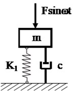
2. The handheld micro tiller vibration model
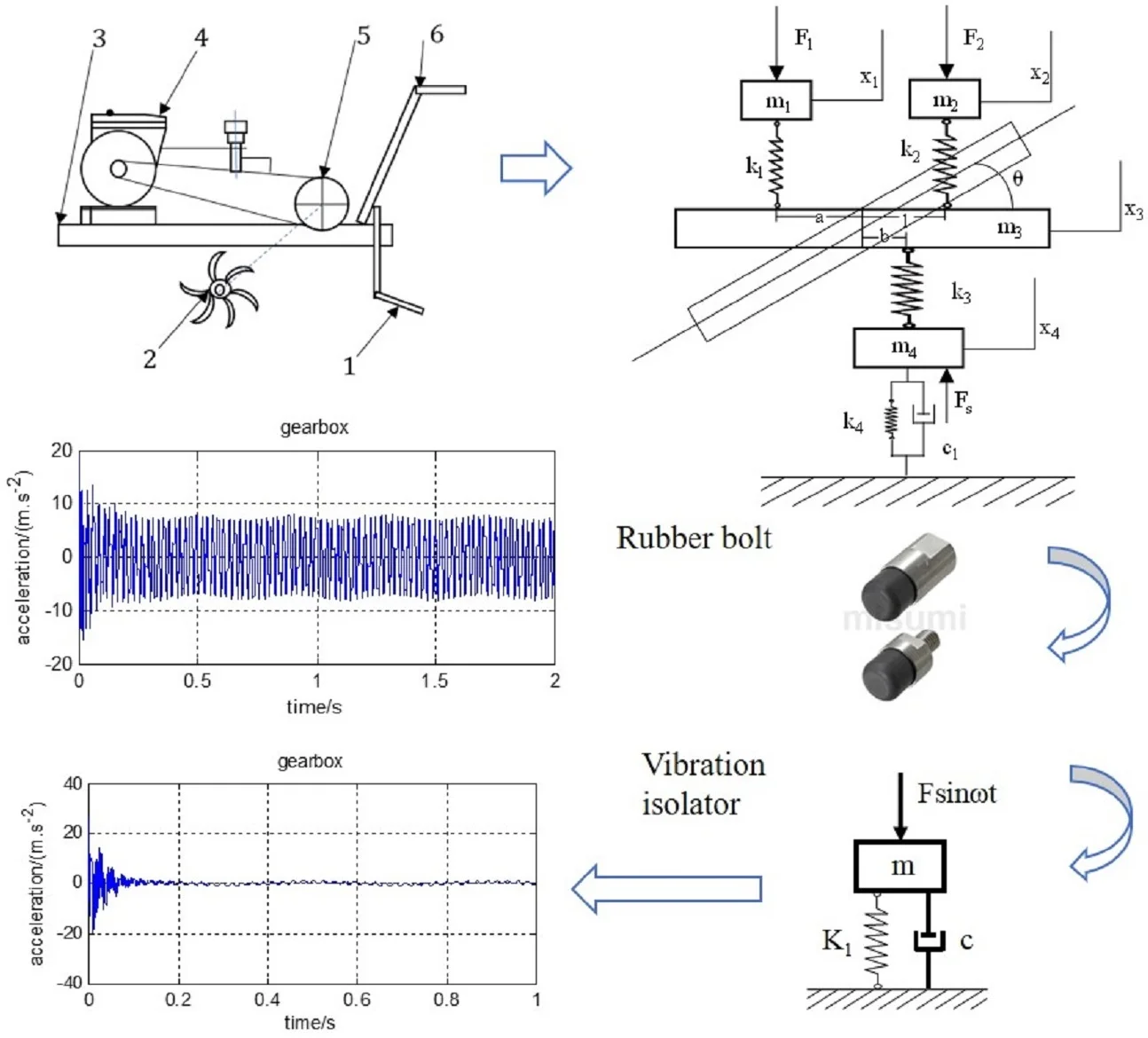
A common diesel driven handheld micro tiller mainly consists of limit deep lever, the rotary blade roll, the frame, the engine, the gear box, and the handrail, as illustrated in Fig. 1.
Fig. 1The scheme of a diesel driven handheld micro tiller: 1 – limit deep lever; 2 – cutter roll; 3 – frame; 4 – engine; 5 – gear box; 6 – handrail
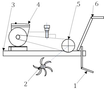
Fig. 2The handheld micro tiller spring mass block
To study the vibration characteristics of a handheld micro tiller, according to the equivalent simplification criterion, a spring mass block model of a common diesel driven handheld micro tiller can be built as shown in Fig. 2, where, , , , represent the mass of the engine, the gearbox and the handrail, the framework, and cutter roll, respectively. , , , represent the vertical displacement of , , , respectively.
is the equivalent stiffness between the engine and frame. is the equivalent stiffness between the gearbox and the frame. is the equivalent stiffness between the cutter roll and the frame. is the equivalent soil stiffness. is the equivalent soil damping. is the slope angel of the frame rotating around the center of mass. is the center of mass of the frame. is the distance from the engine to the frame. is the distance from the cutter roll to the frame. is the distance from the gear box to the frame. is the excitation force acting on the vertical direction of the engine.
is the force acting on the gearbox along the vertical direction. is the reaction force of cutting soil to the cutter roll.
The vibration equation of the handheld micro tiller was built as follows:
By replacing , , , , , , , , , by , , , , , , , , , , the state equations of the handheld micro tiller vibration model was obtained:
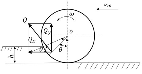
The interaction force between the cutter blade and the soil is quite complex, as shown in Fig. 4. It is hard to test or calculate the exact cutting force. Both the rotational speed of the engine and the forward velocity of the micro tiller have great influence on the cutting force. If only the vertical vibration of the micro tiller is considered, the interaction force between the cutter blade and the soil along the vertical direction can be calculated as follows [11]:
where, is the torque produced by the cutter roller of the micro-tiller (N·m), is the diesel engine power(kw), is the engine revolving speed (r/min); is the cutting force (N), is the rotary blade radius (m); is the angle between the vertical plane and the straight line formed by the resultant force of the cutting force and the center of the cutter roller (rad), as shown in Fig. 3.
Fig. 3The reactive force of the soil to the cutter blade
The engine crank and rod mechanism can be regarded as an equivalent system composed of reciprocating motion mass and rotary motion mass. The reciprocating motion mass includes the piston group and the small end of the rod. It makes a reciprocating variable-speed linear motion along the center line of the cylinder to generate reciprocating inertial force. The rotational motion mass mainly includes the crank and the big end of the rod. It rotates around the axis of the crankshaft to generate centrifugal inertial force. When the engine works, the reciprocating inertial force and centrifugal inertial force are transmitted to the frame through the engine support.
Only considering the effect of the excitation force generated by the engine vibration on the vertical vibration, the inertial force generated by the engine can be calculated as follows [12]:
where, is the mass of the piston (kg); is the radius of the crankshaft (m); is the angular velocity of the crankshaft (rad/s); is the ratio of rod diameter to length.
Considering the gravity of the handrail and the force exerted by the hand on the handrail, the force acting on the gearbox along the vertical direction, namely , is about 100 N.
3. Simulation and test
The parameter values of the handheld micro tiller vibration model comes from [3] and were shown in Table 1. And then the time domains of vibration model were conducted with MATLAB. The simulation time last for 1 second.
Table 1The parameter values
Parameter | Value | Parameter | Value |
/kg | 27 | /N·m-1 | 4.5×10⁶ |
/kg | 22 | /m | 0.126 |
/kg | 25 | /m | 0.087 |
/kg | 28 | /m | 0.082 |
/N·m-1 | 5.5×10⁷ | /N·s·m-1 | 4.5×10³ |
/N·m-1 | 5.5×10⁷ | kg·m2 | 72 |
/N·m-1 | 7.5×10⁷ | /N | |
/N | 763 | /N | 100 |
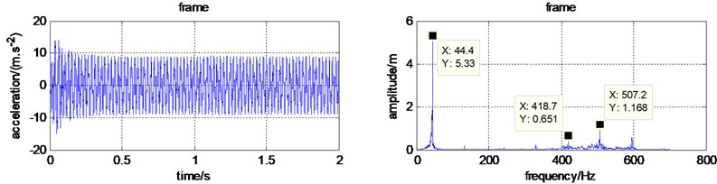
To figure out which part vibrates most seriously, the RMS value for each part were calculated. The results are shown in Table 2. Obviously, the frame vibrates most seriously, and then the gear box. is the equivalent mass of the gearbox and the handrail. It indicates that the handrail also vibrates severely, which leads to white figure disease for the operators.
Table 2The simulated RMS values
Main components | Simulated RMS/(m/s²) with constant cutting force | Simulated RMS/(m/s²) with fluctuating cutting force |
Engine | 4.88 | 4.79 |
Gearbox | 5.28 | 5.13 |
Frame | 5.33 | 5.22 |
Cutter roll | 5.03 | 5.22 |
Frame rotation | 0.281 | 0.25 |
The simulated RMS values were then compared to the tested RMS values, as shown in Table 3. It can be seen the simulated RMS of the gear box is very close to the tested values, the error is only 7 %. The error between the simulated RMS of the frame box and the tested value is nearly 27 %. The big error is the caused by several possible factors. Firstly, the equivalent stiffness is not strictly accurate. Secondly, the soil cutting force is not constant as we have assumed. It is fluctuant as the cutter roll rotates. However, it still indicates that the vibration model is effective to some extent.
Table 3The simulated RMS value compared to tested RMS value
Position | Tested RMS / m/s² | Simulated RMS / m/s² | Error / % |
The frame | 7.33 | 5.33 | 27.28 |
The gear box | 4.93 | 5.28 | 7.00 |
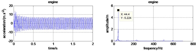
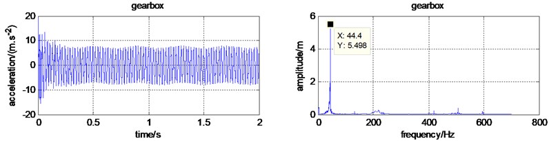
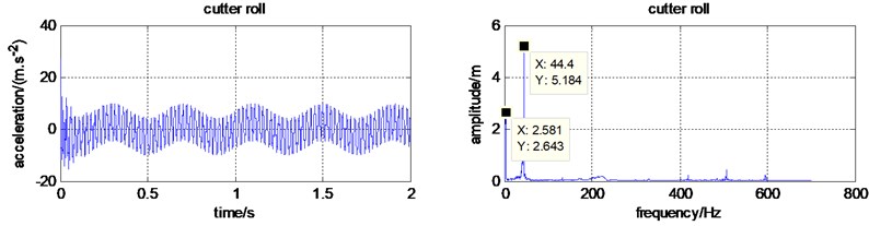
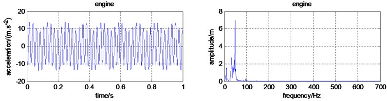
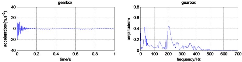
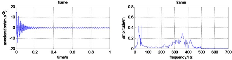
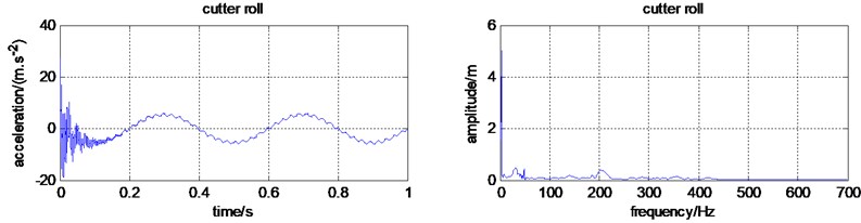
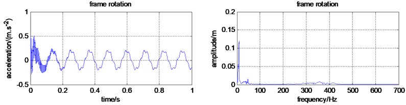
The inertial force generated by the engine is . According to , it can be calculated that the rotational frequency of the engine is 43.8 Hz. The time-frequency domain characteristics for each component were simulated and shown in Fig. 4. It is easy to find that the dominating frequency is 44.48 Hz. It coincides with the inertial force generated by the engine, which indicates that vibration of the handled micro tiller is a kind of forced vibration caused by the engine.
Fig. 4The simulated time and frequency domain with constant cutting force
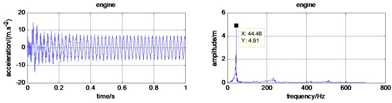
a) Time and frequency domain for the engine
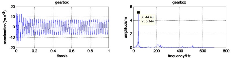
b) Time and frequency domain for the gearbox
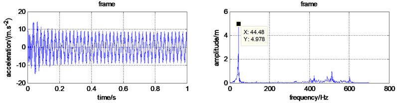
c) Time and frequency domain for the frame
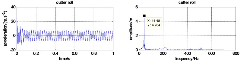
d) Time and frequency domain for the cutter roll
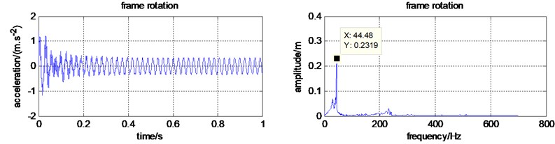
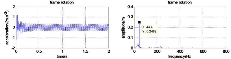
e) Time and frequency domain for the frame rotation
Fig. 5The simulated time and frequency domain with fluctuated soil cutting force
a) Time and frequency domain for the engine
b) Time and frequency domain for the gearbox
c) Time and frequency domain for the frame
d) Time and frequency domain for the cutter roll
e) Time and frequency domain for the frame rotation
The cutting soil reaction force on the cutter roll is not constant. It should be periodic with the rotation of cutter roll. When a micro tiller is in the fast gear, the cutter roll rotational speed is almost 150 r/min. When it is in the slow gear, the cutter roll rotational speed is almost 90 r/min. Assuming that the cutter roll rotational speed is 150 r/min, the cutting soil reaction force frequency is 2.5 Hz. According to , it can be calculated that the 15.7. Assuming that reaction force amplitude is 10 % of the constant value, namely 763 N, the fluctuating cutting force is .
And then, to study the effect of the reaction force, namely , the time and frequency domain for each part were simulated again and shown in Fig. 5. It is obvious that the domain frequency is still 44.4 Hz. The frequency 2.5 Hz, only appears in the cutter roll frequency domain. It proves that only the vibration of cutter roll is affected by the cutter force. The fluctuation frequency of the cutting force is not transmitted to the frame. The domain exciting vibration source for the micro tiller is the engine. So, to reduce the vibration transmitted to the handrail, vibration isolation device should be on installed on the engine.
3.1. Vibration isolation with rubber bolts and simulation
The combustion force of the mixture in the cylinder of the micro-tiller engine and the second-order inertial force of the engine are the main sources of vibration of the micro-tiller. Considering the portability and space saving of the equipment, it is not advisable to choose a larger vibration isolator. The engine of the tiller is fixed on the frame by four bolts. Rubber bolts have the effect of reducing vibration and impact, and are easy to use. Therefore, we first try to replace the original bolts under the engine with rubber bolts. The rubber bolts selected in this design use a new type of shock-absorbing soft gel damping material. The rubber bolt is shown in Fig. 6.
Fig. 6Rubber bolt
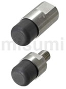
Fig. 7Schematic of rubber isolator system
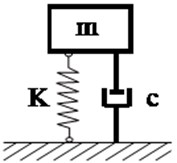
Simplify the rubber bolt into a cylindrical rubber vibration isolator. According to the mechanical design manual, the axial static stiffness can be obtained as:
where is the static shear modulus of the rubber. The dynamic stiffness is , where, is the dynamic-static ratio, the value is 2. The damping is , where 0.06, is the damping ratio.
As shown in Fig. 7, the rubber vibration isolator can be simplified to a spring-damped mass vibration model.
M5×0.8 bolts are generally used on micro-tillers to fixed the engine to the frame. So rubber bolts close to this specification were choose. The four bolts are in parallel. The total stiffness and total damping of the engine part after adding the vibration isolator are as .
Since the mass of the rubber bolt is much smaller than the engine, it can be neglected during the simplification process. So, the vibration model of the handheld micro tiller with rubber bolts were built. And then the model was simulated and analyzed. The RMS value were calculated and compared with the previous RMS data, as shown in Table 4.
It can be seen from Table 4 that the RMS value for each component, when the rubber bolts are used, becomes only a little smaller. We changed the size of the rubber bolt and enlarged the shear modulus of the rubber. However, the damping effect is still limited. It can be concluded that the damping effect of rubber bolts is very limited. A vibration isolator is to be designed to reduce vibration.
Table 4The RMS values with different bolts
Components | Rubber bolts RMS/m/s² | Ordinary bolts RMS/m/s² | ||
2.0×10⁵N·m2 M5 | = 4.0×10⁵N·m-2 M5 | 2.0×10⁵N·m2 M10 | ||
Engine | 4.9689 | 4.9689 | 4.9687 | 4.9781 |
Gearbox | 5.1840 | 5.1861 | 5.1847 | 5.1944 |
Frame | 5.3576 | 5.3899 | 5.3344 | 5.4463 |
Cutter roll | 4.8260 | 4.8349 | 4.8209 | 4.8445 |
Frame rotation | 0.2744 | 0.2747 | 0.2745 | 0.2753 |
3.2. Vibration isolator design and simulation
The spring mass model of vibration isolator is shown in Fig. 8. Among them, , is the total stiffness of the vibration isolator. is the frequency ratio. is the isolator equipment mass. is the excitation circle frequency. , is the vibration isolation coefficient. According to the vibration isolation theory, the most common used frequency ratio is 2.5 to 5 to obtain the best vibration isolation effect [13]. To provide better vibration isolation performance, the frequency ratio is set to 5. The vibration isolator is installed between the engine and the frame. So, the vibration model of the handheld micro tiller with the vibration isolator was built. And then the RMS values were calculated again and compared to the values without the isolator.
Fig. 8Vibration isolator Spring mass model
As shown in Table 5 and Fig. 9, the RMS values of the gearbox, the frame, the cutter box, and the Frame rotation become much smaller. The vibration of the engine did not pass onto other components, which means the vibration transmitted to the human hand is reduced a lot. However, the engine RMS value increase a lot. More reasonable measures to suppress vibration is to be put forward.
Fig. 9The micro tiller time-frequency domain characteristics with isolator
a) Time and frequency domain for the engine
b) Time and frequency domain for the gearbox
c) Time and frequency domain for the frame
d) Time and frequency domain for the cutter roll
e) Time and frequency domain for the frame rotation
Table 5The RMS value with and without the isolator
Components | With the isolator RMS / m/s² | Without isolator RMS / m/s² |
Engine | 8.3748 | 4.9781 |
Gearbox | 2.1326 | 5.1944 |
Frame | 1.7282 | 5.4463 |
Cutter roll | 4.4142 | 4.8445 |
Frame rotation | 0.1419 | 0.2753 |
4. Conclusions
The micro tiller vibration during working process is a kind of multi-source vibration. The external forces applied on various components of the micro-tiller were analyzed. The main components of the handheld micro tiller were simplified. And then the micro-tiller vibration model was built. The time-frequency domain characteristics of the micro-tiller were analyzed.
The RMS values for main components were calculated. The simulated RMS values of the frame and the gearbox are 5.33 m/s2 and 4.88 m/s2 respectively. While the tested RMS values are 7.33 m/s2 and 4.93 m/s2, the errors are 27 % and 7 %, respectively, indicating that the established model is reasonable to a certain extent. The time-frequency domain analysis results show that the excitation force of the engine is the main source of vibration of the micro-tiller.
In order to reduce the vibration transmitted to the handrail, firstly, the ordinary bolts connecting the engine and the frame were replaced with rubber bolts. And then the RMS value was analyzed and calculated. The results showed that rubber bolts could not effectively reduce the vibration of other main components.
Furthermore, it is considered to install a vibration isolator between the engine and the frame of the tiller. Time-frequency domain simulations were performed on the vibration model of the tiller including vibration isolators, and the RMS values of each main component were calculated, and compared to the RMS values without the isolator. The results show that after adding the vibration isolator, the vibration RMS value of each component was much smaller than before. It shows that it isolates the engine vibration effectively. The research in this paper laid the foundation for designing a more reasonable vibration isolator and reducing the vibration of the main components of the tiller.
References
-
K. N. Dewangan and V. K. Tewari, “Vibration energy absorption in the hand-arm system of hand tractor operator,” Biosystems Engineering, Vol. 103, No. 4, pp. 445–454, Aug. 2009, https://doi.org/10.1016/j.biosystemseng.2009.06.001
-
Zhuo W. et al., “Simulation and experimental study on the vibration response of the pre-stressed mini-tiller handle,” (in Chinese), Journal of Agricultural Mechanization Research, Vol. 40, No. 4, pp. 195–199, 2018, https://doi.org/10.13427/j.cnki.njyi.2018.04.037
-
Fang J. et al., “Simulation and experimental study on vibration characteristics of mini tiller,” (in Chinese), Journal of Agricultural Mechanization Research, Vol. 42, No. 4, pp. 203–207, 2020, https://doi.org/10.13427/j.cnki.njyi.2020.04.040
-
Ji Q. et al., “Vibration test and analysis of micro-cultivator machine,” (in Chinese), Journal of Chinese Agricultural Mechanization, Vol. 38, No. 8, pp. 44–49, 2017, https://doi.org/10.13733/j.jcam.issn.2095-5553.2017.08.009
-
Li G. et al., “Vibration test and analysis of mini-tiller,” International Journal of Agricultural and Biological Engineering, Vol. 9, No. 3, pp. 97–103, 2016, https://doi.org/10.3965/j.ijabe.20160903.1979
-
Liu Y. et al., “Analysis of vibration characteristics for power tillers based on a rigid-flexible coupling model,” (in Chinese), Journal of Vibration and Shock, Vol. 37, No. 24, pp. 250–256, 2018.
-
M. Yang, P. Niu, B. Peng, L. Yang, and Z. Peng, “Soil-cutting performance analysis of a handheld tiller’s rotavator by finite element method (FEM),” Inmateh Agricultural Engineering, Vol. 47, No. 3, pp. 13–20, Jan. 2015.
-
Yang J. and Meng X., “Study on vibration mechanism and measures for vibration reducing to the handle of cultivator by virtual prototype technology,” (in Chinese), Transactions of The Chinese Society of Agricultural Machinery, Vol. 36, No. 2, pp. 39–42, 2005.
-
Sun Yuhua, Ke Shangjuan, Wang Guocheng, and Liu Zhibin, “Study on control strategy simulation analysis of a new micro-cultivator mr elastomer vibration isolation system,” (in Chinese), Advanced Engineering Sciences, Vol. 52, No. 4, pp. 218–225, 2020, https://doi.org/10.15961/j.jsuese.201900987
-
Y. H. Ko, O. L. Ean, and Z. M. Ripin, “The design and development of suspended handles for reducing hand-arm vibration in petrol driven grass trimmer,” International Journal of Industrial Ergonomics, Vol. 41, No. 5, pp. 459–470, Sep. 2011, https://doi.org/10.1016/j.ergon.2011.04.004
-
Chinese Academy of Agricultural Mechanization Sciences, Agricultural Machinery Handbook. Beijing: Agricultural Science and Technology Press, 2007.
-
Tao G. et al., “Balance calculation and vibration exciting force analysis for utility small gasoline engine,” (in Chinese), Small Internal Combustion Engine and Motorcycle, No. 6, pp. 30–33, 2011.
-
Wen B. C. et al., Theory of Mechanical Vibration and Its Applications. Beijing: Higher Education Press, 2009.
Cited by
About this article

This work was supported by Key Scientific Research project of Henan Higher Education Institutions (No. 20A416004), Scientific and Technological Breakthrough Foundation of Henan province (No. 202102110266).
