Abstract
This paper presents a new interface technique called synchronous charge extraction and voltage inversion (SCEVI), which consists of a synchronous inductor and a buck-boost converter for vibration-based energy harvesting using piezoelectric elements. The theoretical calculation of the harvested power obtained by using such a technique are proposed and compared with the so-called Standard, SECE (Synchronous Electric Charge Extraction), Parallel-SSHI (Parallel Synchronized Switch Harvesting on Inductor) and Series-SSHI (Series Synchronized Switch Harvesting on Inductor) methods commonly used in piezoelectric vibration-powered generator considering both constant displacement amplitude and force amplitude. From the harvested power point of view, SCEVI and Parallel – SSHI techniques are the better ones and each has its own merits. But the harvested power of SCEVI is independent of the load connected to the generator and Parallel – SSHI depend on the load resistance. The harvested power of SECE is also independent of the load, but the further experimental results show that the proposed SCEVI interface technique dramatically increases the harvested power by almost up to 150 % compared with the SECE method under the same amplitude of displacement excitation.
1. Introduction
Energy harvesting is the energy conversion process by which usable electrical energy is harvested from various ambient energy sources, such as solar power, thermal energy, wind energy, noise, and vibration. The harvesting of mechanical energy in the form of vibration is known to be a very promising approach since vibrations are easily found in almost all kinds of civil structures, machineries and systems with moving parts. Among the energy conversion principles to convert mechanical strain into electrical energy, piezoelectricity has been recognized as one of the most effective and practical ways. The research in vibration-based energy harvesting using piezoelectric materials has received significant attention over the past decades with the overarching goal of eliminating or reducing the dependence of external power sources or batteries to power remotely operated devices. Battery-powered wireless sensors can be troublesome owe to the limited lifespan, irregular recharging or batteries dying without warning and replacement cost of batteries, especially when the sensors are installed in remote locations. The goal of the research in vibration-based energy harvesting is to provide electrical energy for such systems by collecting ambient, otherwise wasted, energy in their environment. With such self-powered capabilities, these devices and sensors can operate in an uninterrupted fashion over prolonged periods of time. The advances in wireless electrical devices, such as wireless sensors and actuators, as well as advances in technologies that make it possible to fabricate such devices at ever smaller sizes have also provided most of the impetus for the rapid growth of the vibration-based energy harvesting field.
Vibration-based Energy Harvesting investigation has received increased attention as regards to improve its performance [1-14], mainly with endeavors in the following varieties: new materials with larger electromechanical coupling, alternative system configurations, and methods of power storage and optimal placement of piezoelectric material. However, since a piezoelectric element subjected to a vibration generates an alternating voltage across electrodes, it is essential to design an interface circuit which converts the alternating current to direct one. Thus, to enhance the electromechanical conversion and an optimal harvested power, the properties of an interface circuit are also important, this problem has been the subject of considerable interest in recent years [9, 10, 12, 15-19]. Several classical interface circuits including Standard, SECE (Synchronous Electric Charge Extraction), Parallel-SSHI (Parallel Synchronized Switch Harvesting on Inductor), and Series-SSHI (Series Synchronized Switch Harvesting on Inductor) techniques are developed in recent years [4, 8, 20, 21]. Among these four classical circuits, Parallel-SSHI technique has the most significant harvested power when its load is optimized. Series-SSHI has a slightly less harvested power compared with Parallel-SSHI. The merit of SECE technique is that its harvested power is independent of its connecting load.
This paper presents a new interface circuit architecture named SCEVI (Synchronous Charge Extraction and Voltage Inversion) mainly composed of a synchronous inductor and a buck-boost converter. From the harvested power point of view, SCEVI and Parallel – SSHI techniques are the better ones and each has its own merits. But the harvested power of SCEVI is independent of the load connected to the generator and Parallel – SSHI depend on the load resistance. The paper is organized as follows. Section 2 exposes a simple electromechanical model to analyze the behavior of the generator. Section 3 expounds the schematic and the working process of SCEVI generator and deduces theoretical harvested powers considering constant displacement amplitude and constant force amplitude. The experimental measurements are carried out to present a comparison between the harvested powers of Standard, SECE, Series-SSHI, Parallel-SSHI and SCEVI techniques when the piezoelectric generator is driven with constant displacement amplitude in Section 4. Finally, Section 5 concludes the paper.
2. Electromechanical model
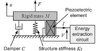
The mechanical and electrical variables of the harvesting system are related by the electromechanical model. Varieties of models of diverse complexity, including lumped- parameter models [4, 16], Rayleigh-Ritz type approximate distributed parameter models [22] as well as numerically distributed parameter FE solution attempts [1, 6]. Lumped parameter model has limited degrees of freedom, but distributed parameter model has infinite degrees of freedom. The former is widely used because of its simplicity and good accuracy, while the latter has higher accuracy but somewhat complicated. In this paper, lumped parameter model is adopted and the mechanical structure bonded with piezoelectric elements can be simply modeled by the ‘mass + piezo + spring + damper’ model which has only one degree of freedom. This model shown in Fig. 1 gives a good description of a vibrational structure when the piezoelectric generator is vibrating near its resonance frequency [4].
Fig. 1Electromechanical model of the piezoelectric energy harvesting system
The dynamic equilibrium of the system can be expressed by:
where is the equivalent rigid mass, is the mechanical loss coefficient, is the equivalent stiffness of the mechanical structure when piezoelectric elements are short-circuited, is the rigid mass displacement, and is the sum of external forces applied to the equivalent rigid mass, including the force produced by piezoelectric elements and the force produced by external excitation.
The standard piezoelectric equations linking the stress , the strain , the electric field intensity and the electric displacement are given in Eq. (2):
where is elastic rigidity of the piezoelectric elements when it is short-circuited, is piezoelectric stress constant and is clamped permittivity.
As:
where and are respectively the section and the thickness of the piezoelectric elements, and are respectively the outgoing current and the voltage across the electrodes of the piezoelectric elements. Substituting Eq. (3) into Eq. (2) yields:
where is the stiffness of the piezoelectric elements when it is short-circuited, is the clamped capacitance, and is the force factor. Their expressions are given in Eq. (5):
Since the rigid mass undergoes the actions of both external force resulting from the mechanical excitation applied on the structure and counter-acting force due to the piezoelectric elements, the relation is obtained. From Eqs. (4), (1), (6) can be obtained:
where is the global stiffness when the piezoelectric elements are short-circuited. The energy conversion equation, which is shown in Eq. (7), can be obtained by multiplying both sides of Eq. (6) by the velocity and integrating over the time variable:
It can be seen that the input energy is divided into kinetic energy , potential energy , mechanical losses and converted energy . The aim of the harvesting system is to make the value of converted energy as large as possible. Eq. (8) is obtained by multiplying both sides of Eq. (4) by the voltage and integrating over the time variable . It can be seen that the converted energy is the sum of electrostatic energy stored on the capacitor and the energy delivered to the electric circuit connected to the electrodes of piezoelectric elements:
The global electromechanical coupling factor as a function of , and is given in Eq. (9). It indicates the ability of energy conversion between the mechanical energy and electrical energy. The larger the global electromechanical coupling factor, the higher the energy conversion efficiency:
3. Theoretical development
This section aims to explain the principle of SCEVI technique. The theoretical performance of the present interface circuit and the so-called Standard, SECE, Parallel-SSHI and Series-SSHI methods commonly used in piezoelectric vibration-powered generator are compared in two different cases of operation: the power generator is respectively driven with a constant force amplitude and a constant displacement one.
3.1. The schematic and working process of SCEVI circuit
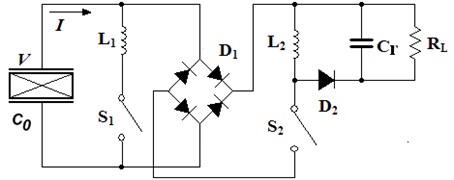
The schematic of SCEVI technique is shown in Fig. 2. It includes the oscillation circuit consisted of piezoelectric patches, inductance and switch , the full wave rectifier bridge consisted of four diodes, and the buck-boost converter consisted of inductance , switch , fly-wheel diode and smoothing capacitor . The external load is replaced by an equivalent resistor . It is obvious that the architecture of this new technique combines the SECE with Parallel-SSHI technique. It is worth noting that it also combines the advantages of both SECE and Parallel-SSHI technique which will be explained below.
Fig. 2The SCEVI interface circuit
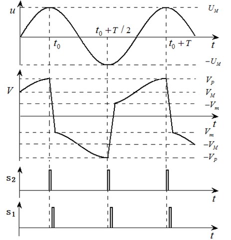
SCEVI technique harvests energy twice in each mechanical vibration period. Each process can be divided into three stages of energy extraction, voltage inversion and open circuit. The vibration displacement , the waveforms of and the control signal , are shown in Fig. 3. The switch (1, 2) is closed when si is high level and the switch is opened when si is low level. The detailed course of the three stages is introduced by taking the time interval as an example.
3.1.1. Energy extraction
At instant , the mechanical displacement reaches its maxima and the voltage of piezoelectric elements reaches its peak value too. Then switch is turned on and the electrical energy stored in the piezoelectric element is delivered to the inductor . The voltage decreases with the transfer of electrical energy. When drops to a supposed voltage , the extraction instants are re-triggered and switch should be turned off. Then the energy stored in the inductor is transferred to the smoothing capacitor and the load through the fly-wheel diode . The harvested power of SCEVI technique in this phase is given in Eq. (10), where is the efficiency of the buck-boost converter:
Fig. 3Theoretical waveforms of the SCEVI circuit
3.1.2. Voltage inversion
Once switch is opened, switch is closed. Hence, an oscillating electrical circuit is constructed. The switch is opened after a half oscillation period, leading to a quasi-instantaneous voltage inversion. However, the voltage inversion is not ideal, implying that there are small energy losses which are mainly due to the inner resistance of the oscillating electrical circuit during this phase. The relation between the voltages of the piezoelectric element before and after the inversion process ( and , respectively) is expressed as following equations:
where represents the inversion factor, and is the electrical quality factor of the electrical oscillator.
3.1.3. Open circuit
In the open circuit case, the switch is turned off and the output current becomes zero. Eq. (13) represents the relationship between the mechanical speed and the voltage derivative. As the mechanical displacement moves in the negative direction, the voltage of the piezoelectric elements decreases. The voltage reaches its negative peak value – when displacement moves to minima – at instant . Thus, Eq. (14) linking the voltage and to the displacement amplitude can be derived by integrating Eq. (13) respect to the time between the interval [, ]:
In order to simplify the harvested power expression, an intermediate variable is introduced, of which definition is given in Eq. (15):
The case 0 means all the energy stored on the piezoelectric elements is transferred into the inductor and SCEVI technique degenerates to SECE technique in this case. The case 1 means no energy is extracted and the harvested power of SCEVI is zero. The case 01 means a part of the electrical energy is transferred.
The harvested energy given in Eq. (16) during a semi pseudo-period can be derived from Eqs. (10)-(14):
Thus the average harvested power of SCEVI technique is:
3.2. The harvested power of SCEVI technique
When the energy harvesting system does not work on its resonance frequency or the electromechanical coupling is weak, the displacement amplitude will remain constant because the harvested energy of interface circuit can be neglected compared to the input energy of external excitation. However, the harvested energy of interface circuit cannot be neglected when the system resonates with external excitation and the electromechanical coupling is strong, which makes the vibration displacement amplitude smaller, and thus the condition of constant displacement amplitude is no longer satisfied for. Therefore, the harvested powers when the piezoelectric generator is driven with both constant displacement amplitude and constant force amplitude will be discussed in the following sections respectively.
3.2.1. Constant displacement amplitude
This section aims to describe the behavior of the SCEVI technique with the assumption that the structure has constant vibration amplitude . Obviously, the expression of average harvested power given in Eq. (17) is a function of . From , the optimal and the corresponding maximum harvested power can be respectively expressed in Eq. (18) and Eq. (19):
Ignoring the resistance of oscillation circuit and the voltage drop of rectifier bridge, the functional relationship between and the triggering time of switch can be expressed as followings:
If is equal to , then the optimal triggering time of switch is given in Eq. (21):
Once the switch is closed, the switch is opened immediately. The switch-on time is equal to a half oscillation period of circuit, yields:
Similar to SECE technique, the energy extraction of SCEVI technique occurs at the extremes of vibration displacement. However, SCEVI technique only transfer part electrical energy into the inductor and the remaining energy is used to invert the voltage by oscillation circuit, while SECE harvests total one. This inversion feature is similar to that of Parallel-SSHI technique. In a certain sense, SCEVI technique could be thought as a synthesis of SECE and Parallel-SSHI technique.
In order to make a comparison among the Standard, SECE, Serial-SSHI, Parallel-SSHI and SCEVI techniques, the theoretical harvested powers of these techniques when the piezoelectric generator is driven with the constant displacement magnitude are summarized in Table 1. In this table, is the optimal load resistance. is the maximum harvested power when the load equates . The harvested power expressions consider the energy conversion efficiency of the buck-boost converter and the energy losses during the voltage inversion, but the power loss of rectifier bridge diodes is not taken into consideration.
Table 1The maximum harvested powers of interface circuits (driven with constant displacement amplitude)
Interface circuits | |||
Standard | |||
SECE | Uncorrelated | ||
Parallel-SSHI | |||
Series-SSHI | |||
SCEVI | Uncorrelated |
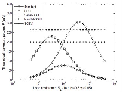
To compare the performance of the aforementioned five kinds of circuits, we vary the load resistance and plot the theoretical harvested powers as a function of the load resistance in Fig. 4. The system parameters given in Table 2 are used in the theoretical simulations.
Fig. 4 shows that only the harvested powers using the SECE technique and the present SCEVI one are independent from the load value. Nevertheless, the power output of SCEVI technique is higher than that of the SECE technique. The maximal harvested power in the Parallel-SSHI case depends on the load value and the load value needs to be tuned to maximize the harvested power. The maximal harvested power in the Parallel-SSHI case is roughly equal to that of SCEVI, but SCEVI technique operates on a wide load range, whereas the Parallel-SSHI technique is limited in terms of load. Overall considering the harvested power and load, the SCEVI technique outperforms the aforementioned four kinds of interface circuits.
Table 2The parameters of the system
Physical meaning | Symbol | Value |
The first-order resonance frequency | 50 Hz | |
Clamped capacitance of the piezoelectric element | 51 nF | |
Force factor | 0.93 mN/V | |
Mechanical vibration displacement amplitude | 0.3 mm | |
Flip coefficient of oscillation circuit of | 0.5 | |
Conversion efficiency of the buck-boost converter | 0.65 | |
Centrifugal force amplitude | 0.04 N | |
Equivalent stiffness of the system | 4000 N/m | |
Equivalent damping of the system | 0.5 N/(m∙s) |
Fig. 4The theoretical harvested powers as a function of the load resistance (driven with constant displacement amplitude)
3.2.2. Constant driving force amplitude
Taking a semi-period [, 2] (as shown in Fig. 3) for example, due to the energy balanceth, mechanical energy provided to the system by driving force with constant amplitude is equal to the sum of the mechanical losses, the harvested energy and the dissipated energy of interface circuit . This energy balance relation is given in Eq. (23). The dissipated energy of interface circuit during a semi-period includes two parts, one of which is the energy dissipated by the switch and the other one is the energy losses of the buck-boost converter. The expression of dissipated energy is given in Eq. (24):
The expression of the energy balance given in Eq. (23) can be simplified with the assumptions that the displacement and the force remain sinusoidal. At the resonance frequency, the ratio of the displacement amplitude to the force magnitude reaches a maximum. Thus, Eqs. (25) and (26) can be obtained:
From Eqs. (23)-(26), the displacement amplitude under the condition of constant driving force can be expressed as Eq. (27):
Substituting Eq. (27) into Eq. (17) yields the harvested power expression of SCEVI technique:
The harvested power of SCEVI technique as a function of and can be obtained from Eqs. (9) and (28). This function is illustrated in Fig. 5. The bold line corresponds to the maximum harvested power curves.
Fig. 5The theoretical harvested power of SCEVI technique as a function of x and k2 (constant force amplitude)
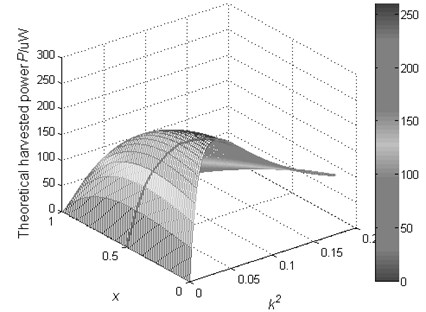
It can be seen from Fig. 5 that the harvested power of SCEVI technique first increases and then decreases with the increase of electromechanical coupling factor. This behavior can be well interpreted from Eqs. (9) and (27). In the weak electromechanical coupling domain, the displacement amplitude tends to decrease as the electromechanical coupling factor increases. Before the electromechanical coupling factor reach an exclusive value, the harvested power increases with the electromechanical coupling factor increases. But in the strong electromechanical couplings domain, the damping effect is significant. Since the external driving force has constant amplitude, the mechanical power received by the structure may be lower than the one in the weak coupling domain because of a strong displacement amplitude reduction, thus, in this domain the harvested power may decrease when the electromechanical coupling factor increases.
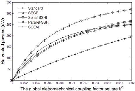
The theoretical maximum harvested powers as a function of using each technique are plotted in Fig. 6 (partial enlarged drawing is shown in Fig. 7). The Standard, Series-SSHI and Parallel-SSHI interfaces can avoid a significant displacement amplitude reduction by adjusting the value of load resistive. Obviously, whether or not relative to the load resistive results in the phenomenon that the theoretical harvested powers of Standard, Series-SSHI and Parallel-SSHI interfaces tend to gradually increase and then become saturated, and those of SECE and SCEVI first increase and then decrease. It can be seen that the SCEVI interface are the most effective technique in the weak coupling domain.
Fig. 6The maximum theoretical harvested powers as a function of k2 (driven with constant force amplitude)
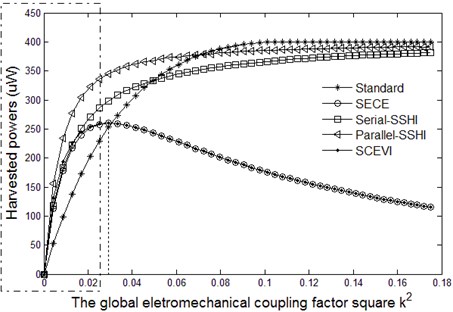
Fig. 7Partial enlarged drawing of Fig. 6
4. Experiments
4.1. Experimental setup
As shown in Fig. 8, the mechanical part of the experimental setup is a cantilever beam. There are four PZT patches by 30×30×0.5 mm3 bonded on the cantilever surface. These PZT patches, which are in turnconnected in parallel, are placed to the vicinity of the clamped end where the strain is maximum for the first flexural mode of the experimental setup. The first order resonance frequency of the energy harvesting system is 49.8 Hz. A 49.8 Hz sine signal outputted by a signal generator is amplified by a power amplifier and then drives an electromagnet to make the beam free-end to vibrate. The cantilever free-end displacement is measured with a laser displacement sensor. The sensor outputs an electrical signal which is proportional to the beam free-end displacement. The electrical signal, an analog signal, is converted to a digital signal by the A/D module. The microcontroller ATmega16 is used to generate the control signals. The extremes of the digital signal are detected by the software program. Once the extremes are detected, the control signals and of the interface circuit can be generated. The parameters of the system are listed in Table 2 and Table 3.
Fig. 8Experimental setup
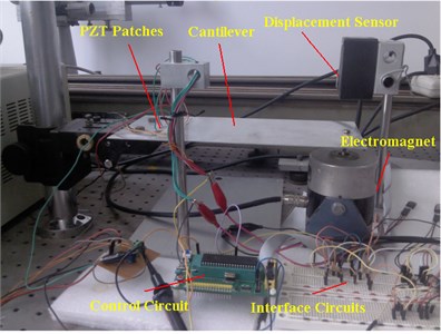
Table 3Parameters of the energy harvesting system
Physical meaning | Symbol | Value |
Open circuit piezoelectric voltage to the beam free-end displacement ratio | 18.2 V/mm | |
Inductor | 20 mH | |
Inductor | 100 mH | |
The voltage drop of diode in the rectifier bridge | 0.25 V |
4.2. Experimental results
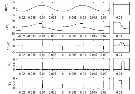
The experimental waveforms of the SCEVI technique is shown in Fig. 9 where is the displacement of the cantilever free-end, and represent the outgoing current and the voltage across the electrodes of the piezoelectric elements respectively. The partial enlarged drawing at the instant 0.01 s is also shown in Fig. 9. It can be seen from Fig. 3 and Fig. 9 that the experimental waveforms are in complete accord with the theoretical ones.
Fig. 9Experimental waveforms of the SCEVI technique
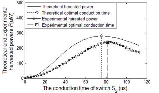
The harvested power as a function of the conduction time of switch can be obtained from Eqs. (17) and (20). Their theoretical and experimental results under the circumstance of constant displacement amplitude are shown in Fig. 10. It can be seen that the experimental waveform is similar to theoretical waveform but slightly smaller, the main reason is that the theoretical calculation does not take the power losses of diode bridge rectifier into account.
Fig. 10The harvested power of SCEVI technique as a function of the switch S2 on-time
Lastly, the experimental measurements are carried out to present a comparison between the Standard, SECE, Series-SSHI, Parallel-SSHI and SCEVI techniques when the generator is driven with constant displacement amplitude. The vibration displacement amplitude is 0.3 mm and the corresponding open circuit voltage of PZT patches is 6 V. Under this condition the experimental comparison results are depicted in Fig. 11 and the theoretical comparison results have been given in Fig. 4.
Fig. 11The experimental harvested powers as a function of the load resistance when the generator is driven with constant displacement amplitude
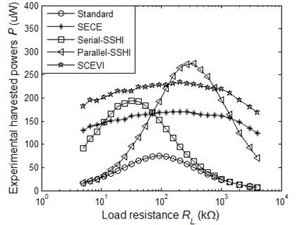
By comparing Fig. 4 and Fig. 11, it can be seen that the experimental harvested powers is slightly smaller than the theoretical ones, which is mainly due to the theoretical calculation does not consider the power losses of diode bridge rectifier. In Fig. 11, the harvested powers of SECE and SCEVI techniques first increases and then decreases with the increase of load resistance. This phenomenon is different from the theoretical prediction due to the impedance of the measuring instruments being not large enough. For lower load resistance, higher current values through the inductor increase resistive losses. While for higher load resistance, the parallel leakage resistor of the smoothing capacitor produces a non-negligible effect on the real resistive load.
5. Conclusions
The research on the piezoelectric energy harvesting system which can convert ambient vibrational energy to electrical energy has attracted widespread attention of scholars in recent years. As an essential component, the interface circuits play a vital role to improve the harvested power. Several techniques including Standard, SECE, SSHI, DSSH, and ESSH and so on are developed to make the harvested power as large as possible. In this paper, a new technique called SCEVI is designed and its theoretical harvested power is calculated considering the constant displacement amplitude and force amplitude respectively. Theoretical results show that the harvested power of SCEVI technique and the maximum harvested power of Parallel-SSHI are approximately the same level, and the load resistance has a major impact on the harvested power of Parallel-SSHI but little on SCEVI. The harvested power of SECE is also independent of the load, but the further experimental results show that the proposed SCEVI interface technique dramatically increases the harvested power by almost up to 150 % compared with the SECE method under the same vibration condition. The experimental results also demonstrate that the harvested power of SCEVI is only slightly smaller than that of Parallel-SSHI. Overall considering the harvested power and load, the SCEVI technique outperforms the aforementioned four kinds of interface circuits.
References
-
Noh J. Y., Yoon G. H. Topology optimization of piezoelectric energy harvesting devices considering static and harmonic dynamic loads. Advances in Engineering Software, Vol. 53, 2012, p. 45-60.
-
Liao Y., Sodano H. A. Optimal placement of piezoelectric material on a cantilever beam for maximum piezoelectric damping and power harvesting efficiency. Smart Materials and Structures, Vol. 21, Issue 10, 2012, p. 105014.
-
Rupp C. J., Evgrafov A., Maute K., Dunn M. L. Design of piezoelectric energy harvesting systems: a topology optimization approach based on multilayer plates and shells. Journal of Intelligent Material Systems and Structures, Vol. 20, Issue 16, 2009, p. 1923-1939.
-
Lefeuvre E., Badel A., Richard C., Petit L., Guyomar D. A comparison between several vibration-powered piezoelectric generators for standalone systems. Sensors and Actuators A: Physical, Vol. 126, Issue 2, 2006, p. 405-416.
-
Shu Y., Lien I. Efficiency of energy conversion for a piezoelectric power harvesting system. Journal of Micromechanics and Microengineering, Vol. 16, Issue 11, 2006, p. 2429-2438.
-
De Marqui Junior C., Erturk A., Inman D. J. An electromechanical finite element model for piezoelectric energy harvester plates. Journal of Sound and Vibration, Vol. 327, Issue 1-2, 2009, p. 9-25.
-
Shu Y., Lien I. Analysis of power output for piezoelectric energy harvesting systems. Smart Materials and Structures, Vol. 15, Issue 6, 2006, p. 1499-1512.
-
Lefeuvre E., Audigier D., Richard C., Guyomar D. Buck-boost converter for sensorless power optimization of piezoelectric energy harvester. IEEE Transactions on Power Electronics, Vol. 22, Issue 5, 2007, p. 2018-2025.
-
Shen H., Qiu J., Ji H., Zhu K., Balsi M. Enhanced synchronized switch harvesting: a new energy harvesting scheme for efficient energy extraction. Smart Materials and Structures, Vol. 19, Issue 11, 2010, p. 115017.
-
Lallart M., Richard C., Garbuio L., Petit L., Guyomar D. High efficiency, wide load bandwidth piezoelectric energy scavenging by a hybrid nonlinear approach. Sensors and Actuators A: Physical, Vol. 165, Issue 2, 2011, p. 294-302.
-
Ferrari M., Ferrari V., Guizzetti M., Andò B., Baglio S., Trigona C. Improved energy harvesting from wideband vibrations by nonlinear piezoelectric converters. Sensors and Actuators A: Physical, Vol. 162, Issue 2, 2010, p. 425-431.
-
Lallart M., Guyomar D. An optimized self-powered switching circuit for non-linear energy harvesting with low voltage output. Smart Materials and Structures, Vol. 17, Issue 3, 2008, p. 035030.
-
Anton S. R., Sodano H. A. A review of power harvesting using piezoelectric materials (2003-2006). Smart Materials and Structures, Vol. 16, Issue 3, 2007, p. R1-R21.
-
Guyomar D., Badel A., Lefeuvre E., Richard C. Toward energy harvesting using active materials and conversion improvement by nonlinear processing. IEEE Transactions on Ultrasonics, Ferroelectrics and Frequency Control, Vol. 52, Issue 4, 2005, p. 584-595.
-
Wu W., Wickenheiser A., Reissman T., Garcia E. Modeling and experimental verification of synchronized discharging techniques for boosting power harvesting from piezoelectric transducers. Smart Materials and Structures, Vol. 18, Issue 5, 2009, p. 055012.
-
Lallart M., Garbuio L., Petit L., Richard C., Guyomar D. Double synchronized switch harvesting (DSSH): a new energy harvesting scheme for efficient energy extraction. IEEE Transactions on Ultrasonics, Ferroelectrics and Frequency Control, Vol. 55, Issue 10, 2008, p. 2119-2130.
-
Lallart M., Guyomar D. Piezoelectric conversion and energy harvesting enhancement by initial energy injection. Applied Physics Letters, Vol. 97, Issue 1, 2010, p. 014104.
-
Lallart M., Lefeuvre É., Richard C., Guyomar D. Self-powered circuit for broadband, multimodal piezoelectric vibration control. Sensors and Actuators A: Physical, Vol. 143, Issue 2, 2008, p. 377-382.
-
Liang J., Liao W.-H. Improved design and analysis of self-powered synchronized switch interface circuit for piezoelectric energy harvesting systems. IEEE Transactions on Industrial Electronics, Vol. 59, Issue 4, 2012, p. 1950-1960.
-
Kong N., Ha D. S., Erturk A., Inman D. J. Resistive impedance matching circuit for piezoelectric energy harvesting. Journal of Intelligent Material Systems and Structures, Vol. 21, Issue 13, 2010, p. 1293-1302.
-
Shu Y., Lien I., Wu W. An improved analysis of the SSHI interface in piezoelectric energy harvesting. Smart Materials and Structures, Vol. 16, Issue 6, 2007, p. 2253-2264.
-
DuToit N. E., Wardle B. L. Experimental verification of models for microfabricated piezoelectric vibration energy harvesters. AIAA Journal, Vol. 45, Issue 5, 2007, p. 1126-1137.
About this article

This research is supported by the National Natural Science Foundation of China (Grant No. 11172129) and the Aeronautical Science Fund under grant 2012ZA52009, the Priority Academic Program Development of Jiangsu Higher Education Institutions and Qing Lan Project.
