Abstract
Different kinds of artifacts can occur during a computer tomography (CT) scans due to hardware or software related problems, human physiologic phenomenon or physical restrictions. Some of them can seriously affecting diagnostic image quality, while others may simulate or be confused with different pathology. On another words artifact is an artificial feature appearing in an image that is not present in the original investigative object. It is important to recognize these artifacts according to a basic understanding of their origin, especially those mimicking pathology, as they can lead to incorrect diagnosis and cause serious after-effects on patient’s health. We presented an overview of the most common CT artifacts and methods to fix or rectify them. We also provide the original artifacts images and statistics from the Lithuanian University of Health Sciences Kaunas Clinical Hospital obtained from image databases.
1. Introduction
More and more often due to technical or software problems, physiological or physical causes, different types of artifacts are present in the CT diagnostic images. Some of these artifacts degrade the value of diagnostic image by overlapping the important anatomical structures, while others can mimic pathological changes. Artifacts can diminish or degrade quality of images or sometimes make them diagnostically unusable. An artifact could be defined as an artificial peculiarity, content or information of the image that is not present in the real object. It’s very important to recognize these artifacts and their nature, because false diagnosis based on corrupt images can directly and seriously influence health of the patient. The term artifact is applied to any systematic discrepancy in the reconstructed image and the true attenuation coefficients of the object [1]. So, artifact is an error or distortion in an image that is unrelated to the subject being imaged [2]. CT images are inherently more prone to artifacts than conventional radiographs because the image is reconstructed from something on the order of a million independent detector measurements. The reconstruction technique assumes that all these measurements are consistent, so any error of measurement will usually reflect itself as an error in the reconstructed image [1, 3]. According to their origin artifacts mostly grouped into four main categories [1]:
1) “physics-based” artifacts – as result of the physical processes involved in the obtaining of CT scans;
2) “patient-based” artifacts – directly associated with conscious or unconscious patient movements during the scan or the presence of ferromagnetic origin foreign structures in/ on the patient body;
3) “hardware-based” artifacts, as a result from hardware malfunction;
4) “helical” and “multisection” artifacts, which can be produced by the time of image reconstruction process.
In this paper in conformity with literature resources and our own experience we overlook the main categories, causes and propose clinical samples of the most common encountered CT artifacts as well as methods to avoid or diminish their influence formulating final diagnosis. Also we perform quantitative and qualitative analyses of the artifacts detected in the imaging modalities and discuss about their correction possibilities.
2. Materials and methods
The study was conducted in Lithuanian University of Health Sciences Kaunas Clinical Hospital. Patients ranged in age from 3 to 91 years. Images of 415 patients selected randomly examined by means of CT, using a clinical image database. Image acquisitions were performed by three CT units: Siemens Somatom Emotion 6 (Siemens AG, Healthcare Sector, Erlangen, Germany) GE LightSpeed Pro 16 (GE Healthcare, United Kingdom, Buckinghamshire), GE LightSpeed VCT (GE Healthcare, United Kingdom, Buckinghamshire). All rehearsed CT devices were of fifth generation with integrated artifact correction software. For detailed analysis we selected images with enough visible artifacts, cases with beam hardening artifact were included only if the artifact was obvious and interfered with adjacent anatomical body structures. Average radiation exposure dose was evaluated in every case, CT artifacts were described in details as well as their types and correction capabilities, schemes and original images were also included.
3. Results
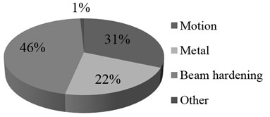
Subset was completed out of 46 % (n-54) female, 54 % (n-64) male patients. Average radiation exposure dose for patient was 1774 DLP (dose-length product, conversion factor for computed CT dosimetry). 115 cases (or series of images) out of 415 (27.8 %) were with artifacts. The most frequent were beam hardening artifacts (45.7 %), patient motion artifacts (31.3 %), and ferromagnetic (metal) origin artifacts (22.0%). Other types of artifacts were comparatively rare and completed < 1 % of all the images with artifacts (Fig. 1(a)). Age or gender don’t influenced to the incidence and number of artifacts as well as type and model of CT device.
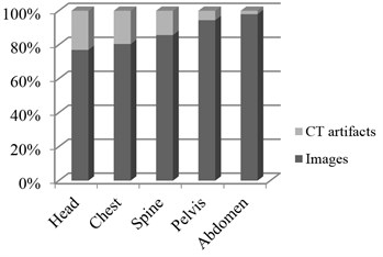
Analysis shown 29.9 % of artifacts presented in cerebral CT investigations, 24.3 % – thoracic, 16.6 % – spinal, 5.8 % – pelvic, and 2.0 % – abdominal. We are of the opinion that high incidence of artifacts in the head CT scans, generally is because of head are more prominent to motion; it’s easier for a patient to accidentally move head during CT scanning. As an instance, beam hardening artifacts are more often in head because there is a lot different density structures lying near each other. The next highest numerically artifacts were detected performing thoracic and spinal CT scans. By our eyes, they also are associated with patient’s motion and arise because of heart and magisterial vessels pulsation as well as uncontrolled respiratory chest moving. Other types of artifacts were enough rare and completed 1 % of all the images with artifacts (Fig. 1(b)).
Fig. 1a) CT artifacts selected by type and b) site of investigation
a)
b)
The most (92 %) of artifacts were detected performing CT scanning in the Emergency CT unit. Only 4 % of artifacts were detected in the neurosurgery/neurology CT unit and 4 % of artifacts – in general CT unit.
4. Discussion
It is obvious that different kinds of artifacts in CT images are quite common in clinical practice. According to our experience they are detected in more than a quarter of all the CT scans, thus it is very important to identify them and timely to make necessary corrections. As illustrated in our results the most frequent artifacts are observed in emergency unit. Various reasons of this problem included technical, physical, human factors, etc. One of the reasons of this could be enough high intensity of workload, mixed and complicated pathologies, critical state of patient’s health, inability to make correct at a moment positioning or immobilization of the patient, insufficient interaction with the patient and sometimes not adequate anesthesia, what is especially common in emergency units. In opposite, this significantly rare doing scheduled CT investigations. Second, what can also be important – different experience of staff, working in the same Clinical hospital with different types of CT devices and software, despite integrated artifacts detection programs in new generation CT scanners, which are enough far to perfection. Every so often it takes difficulties for recognition of artifacts and selection of appropriate method for correction in image interpretation process.
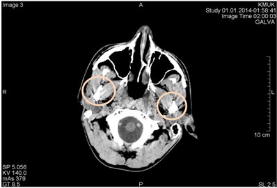
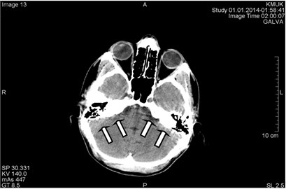
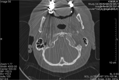
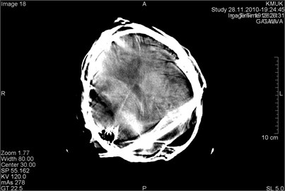
Beam hardening is one of the most frequent physical-based types of artifact. According to some sources this artifact accounted near 21 % of repeated CT scans [4]. Normally an x-ray beam is composed of individual photons with a different range of energies. When the beam passes through a scanning object, it becomes “harder,” since of mean energy increases. Two common types of artifact resulted from this effect are described in literature: cupping and the streaks appearance between dense objects in the image [1]. Cupping artifacts originate when X-rays passing through the middle portion of the same scanning object and are “more hardened” comparing those passing though the edges. This physical effect results in a characteristic of cupped shape. Streaks artifacts originate when the beam that passes through one of the objects at certain tube positions and is “hardened less” comparing when it passes through both objects at other tube positions. Typical clinical examples of both type beam hardening artifacts are presented in Fig. 2 and Fig. 3.
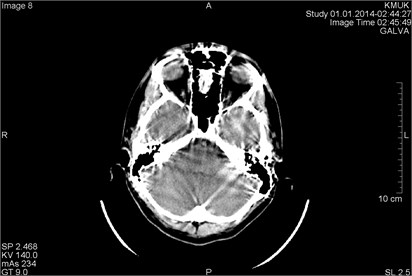
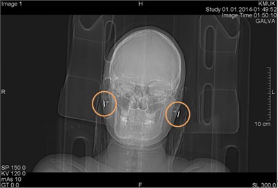
Fig. 2CT scans axial projections in different levels of the head of the same patient. Visible beam hardening artifacts generated between high-density objects: a) surrounded by circles, b) marked by arrows
a)
b)
These types of artifacts are not difficult to detect because they are distinctly artificial. Possible fix for this type of artifact would be to avoid scanning bony regions if possible. It can be done by different patient positioning or by tilting the gantry. The second way – select the appropriate scan field of view to ensure that the scanner will use the correct calibration and beam hardening correction data. Its significant fact, that this type of artifacts can by only minimized in a certain level, but is impossible them totally eliminate. Most manufacturers in final generation CT scanners have built-in features like filters, calibration correction and beam hardening correction software for minimizing beam hardening artifacts, but at yet it’s far away from ideal. It is possible to diminish artifacts by using dual energy CT [2, 5].
Other physical-based types of artifact named “partial volume”, “photon starvation” and “undersampling” happens rarely enough and according to our experience haven’t significant clinical importance.
Fig. 3CT scans axial projection: visible intense beam hardening artifacts
Patient-based artifacts are presented by few types of artifacts: “ferromagnetic” (metal origin) material induced, patient “motion” induced and because of “incomplete projection”.
Metal based artifacts are observed in cases, when artificial (mainly metal) objects are presented on/in scanning body or scanning field. Mostly it can be various types of earrings, metal clips, metal plates, dental braces, artificial heart or joint, dental and other body site implants. The same we can say about permanent make-up and tattoos, what is popular recently. These objects evoke streaking like artifacts which occur because the density of the metal is beyond the normal range that can be computed by the software, resulting in an incomplete attenuation profiles.
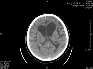
Fig. 4CT scans axial projection. Visible bright metal artifacts arising from the right ear (marked by arrows)
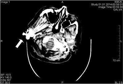
This type artifact can be easily detected and avoided by the operator. Patients should be asked to take off removable metal objects such as jewelry before scan procedure. For non-removable items, such as dental fillings, prosthetic devices, and surgical clips, it is sometimes possible to change gantry angle and exclude the metal inserts from scans of needed scanning anatomy sites. Another way for correction could be increasing penetration of some objects by raising kilovoltage. Of course, it associate with little bit more high patient irradiance, but clinically it don’t make marked problems. Third method based on using of thinner sections which can reduce artifact. Artifact reduction software made by manufacturers is limited because, although streaking distant from the metal implants is removed, there still remains a loss of detail around the metal-tissue interface, which might be in the area of diagnostic interest. Examples of metal artifacts representing CT scans demonstrated in Figs. 4-7.
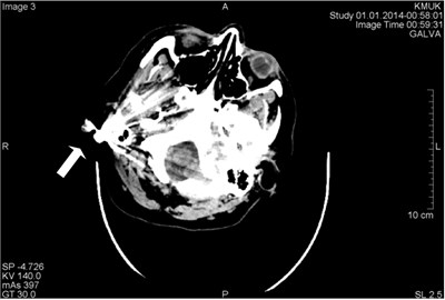
Fig. 5CT scans axial projection: a) visible bright metal artifacts arising from the right ear, b) CT topogram, where origin of the artifacts are earrings (surrounded by circles)
a)
b)
Fig. 6CT scans axial projection of the same patient: a) metal artifact on the abdominal wall projection, b) CT topogram with clearly visible origin of artifact – navel ring, surrounded by a circle
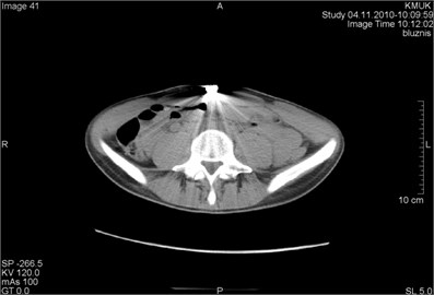
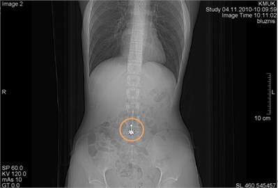
Fig. 7CT scans axial projection: a) intense metal artifacts and bone window of the same patient, b) visible artifacts caused by multiple dental crowns
a)
b)
Motion artifacts ordinary are associated with involuntary movements of patient’s body: heart beating and respiratory chest movements, vascular pulsation movements, seizures type movements. Voluntary movements include cases scanning small age (pediatric) patients, patients with alcohol or drugs intoxication, patients with various degree consciousness disorders, and sometimes incompletely sedated patients. Patient motion commonly can cause shading or streaking artifacts in the reconstructed images, presented in Figs. 8-10.
The use of positioning aids often is sufficient to prevent voluntary movements of the most patients. For pediatric patients it may be necessary to immobilize the patient by means of sedation. Respiratory motion can be minimized if patient is able to hold his breath for the duration of the scan. Using the most possible short scan time as possible sometimes helps to minimize artifacts when scanning regions which are prone to movement. Radiology technologist should always specify body scan mode.
Manufacturers minimize motion artifacts by using over scan and under scan modes, software correction, and cardiac gating [3].
Incomplete projection artifact are quite rare and observed, when any portion of the patient lies outside the scan field of view, the computer will have incomplete information relating to this portion and streaking or shading artifacts are likely to be generated. Similar effects can be caused by dense objects such as metal objects or intravenous tube containing contrast medium lying outside the scan field [1]. To avoid these type artifacts due to incomplete projections, it is essential to position the patient so that no parts lie outside the scan field.
Fig. 8CT scans axial projection on the same patient (different slices). In both panels presented artifacts arising from the movement of the patient during the study
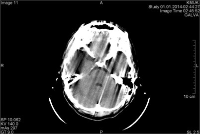
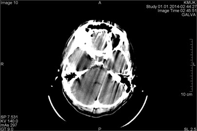
Fig. 9CT scans axial projection: a) motion artifacts cover the hemorrhage in the right frontal part of the brain (marked by arrow), b) very bright motion artifacts due to the patient’s active head movement during the scan
a)
b)
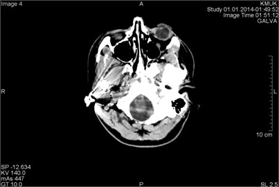
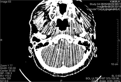
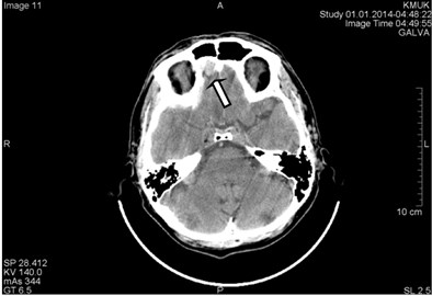
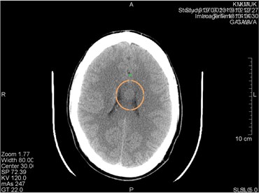
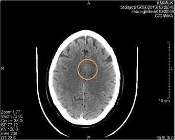
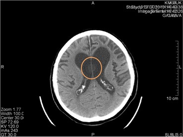
Hardware-dependent artifacts commonly represent so-called “ring” artifacts. They can occur if one of the detectors is out of calibration and give a consistently erroneous reading at each angular position, resulting in a circular artifact [6]. In Figs. 10-11 are represented appropriate samples of such type artifacts. In cases when they are visible, it be confused with possible disease and impair the diagnostic quality of an image.
The presence of circular artifacts in an image is an indication that the detector gain needs recalibration or may need hardware repair. All modern scanners use solid-state detectors, and their potential for ring artifacts is reduced by optimized software.
Fig. 10CT scans axial projection. a) Visible artifact caused by the CT machine tube failure (marked by a circle). After changing the tube artifact disappeared. b) CT scan axial projection with analogical artifact caused by the hardware problems (surrounded by a circle). This artifact can be easily confused with a brain lesion
a)
b)
Fig. 11CT scans axial projection on the same patient: a) visible hardware-depended origin artifact marked by circle, b) another CT slice. Artifact disappeared
Helical and Multisection CT Artifacts are seen in helical scanning same as in sequential scanning. This type of artifacts occurs when anatomic structures change rapidly in the direction [1, 7]. In clinical images helical artifacts can easily be misinterpreted as disease. Whereas helical and multisection CT artifacts are rare, they don’t have great clinical significance.
5. Conclusions
CT artifacts are common in medical imaging and amount over quarter of all CT scans. A huge part of artifacts influence the quality of diagnostic imaging and could be misinterpreted as pathological findings. Apprehension of artifacts enables staff of radiology departments to keep high level of diagnostic ability, recognition of artifacts and selection of appropriate method for correction is very important point in image interpretation process. The best way to eliminate artifacts is to avoid them by using modern and well calibrated scanners, appropriate scanning protocols and proper patient preparation. If artifacts are unavoidable, you should use techniques which minimize artifacts so the image quality wouldn’t be heavily affected.
References
-
Julia F. Barrett, Nicholas Keat Artifacts in CT: recognition and avoidance. RadioGraphics, Vol. 24, 2004, p. 1679-1691.
-
F. Edward Boas, Dominik Fleischmann CT artifacts: causes and reduction techniques. Imaging in Medicine, Vol. 4, Issue 2, 2012, p. 229-240.
-
Barrett J. F., Keat N., Platten D., Lewis M. A., Edyvean S. Cardiac CT scanning. MHRA Report 03076. London, England: Medicines and Healthcare Products Regulatory Agency, 2003.
-
Issa Al-Shakhrah, Tariq Al-Obaidi Common artifacts in computerized tomography: a review. Applied Radiology, 2003.
-
Kachelriess M., Watzke O., Kalender W. A. Generalized multi-dimensional adaptive filtering for conventional and spiral single-slice, multi-slice, and cone-beam CT. Medical Physics, Vol. 28, 2001, p. 475-490.
-
Hsieh J. Image artifacts: appearances, causes and corrections. Computed Tomography: Principles, Design, Artifacts and Recent Advances, SPIE Press, Bellingham, Wash, 2003, p. 167-240.
-
Taguchi K., Aradate H. Algorithm for image reconstruction in multi-slice helical CT. Medical Physics, Vol. 25, 1998, p. 550-561.
-
Seeram E. Image quality. Computed Tomography: Physical Principles, Clinical Applications and Quality Control. 2nd Ed. Philadelphia, Saunders, 2001, p. 174-199.
-
Wilting J. E., Timmer J. Artifacts in spiral-CT images and their relation to pitch and subject morphology. European Radiology, Vol. 9, 1999, p. 316-322.
About this article

