Abstract
This paper presents the experimental study and numerical simulation on the influence of the constructional damping of mounting on the beetle wing-based frame vibrations. The physical model consist of four parts arranged horizontally and is based on the main structure of wing venation. The damping vibration was modelled by placing individual hyper viscous rotary dampers supports. The numerical modelling results and the experimental data were compared.
1. Introduction
Recent years have seen the increasing popularity of biomimetic engineering. Designers seek to imitate the flapping wing flight of animals, because it offers some unique advantages. It has the potential for both the lower weight and to maneuver in small spaces. The micro air vehicles (MAV’s) have been the subject of much recent research. A particularly new trend in the MAV developers is to take inspiration from flying insects.
Understanding wing-flapping mechanism is only possible when the wing structure is fully analysed. In the work [1] the author describes and evaluates flight behaviour of insects. The biomechanical aspects of the insect wing were studied in the work [2]. The authors analysed the mechanical load-bearing capacity of the simplified dragonfly wing model. The model was loaded perpendicularly as a homogeneous wing loading. The authors used the finite element method (FEM) to quantify the quality of material distribution. Also the stabilizing constructional elements of the wing were described.
In the paper [3] the authors described the multiple functions of the resilin in beetle wings: correlation with the wing folding pattern and providing extra wing elasticity to prevent the material damage or to be deformed by the aerodynamic forces. The mechanical properties of the biomaterial were also investigated in the works [4, 5] and [6]. In the paper [7] the authors analysed and compared the mechanical performance of cuticle with other materials using material property charts and indices, such as: density, specific strength, toughness and hardness.
In order to design a MAV one must mechanically mimic the insect's wing. Hence the analysis of wing-based frame vibration damping must be performed. In the paper [8] the authors applied the complex mode superposition method to the dynamic analysis of a Bernoulli-Euler simply supported beam. Additionally two rotational viscous dampers where attached at its end. The authors indicated that the appropriate choice of the damper constant allows for the maximum reduction of the dynamic response.
An example of a rotary dampers application can be found in work [9], in which the problem of T – type frame damped vibration was researched. Typically T-type frame constructions could be found in aerospace application.
This work was undertaken to examine the influence of constructional damping in the wing-based frame mounting. The frame was based on the simplified model of Mecynorrhina Torquata beetle wing. In order to mimic the mechanical characteristics of the biological structure, the authors performed the analytical research to determine the material properties of the beetle’s wing venation. An experiment for the evaluation of the obtained results was also carried out.
2. Methodology
In biological terms wings refer to the thoracic structures responsible for generating aerodynamic forces. A fully expanded wing is made of double-layered membrane supported by veins. Wing veins are typically hollow and circular in cross-section [1].
The exact material properties of natural components may be difficult to determine. The material properties such as Young’s modulus can vary greatly not only among insect orders and families but also within a wing. In order to perform the mathematical analysis the knowledge of the material properties is essential. Therefore the authors defined constant material density 2600 [kg/m3] and Young’s modulus 0.3 [GPa] to be used in the mathematical computations.
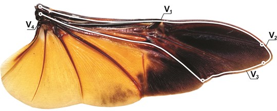
Geometrical data derived from wing measurement performed by the authors. The venation serves to strengthen the wing structure. The physical model was based on the main structure of the wing venation (, , in Fig. 1). It consists of four beams arranged horizontally. The lengths correspond to the dimensions of the investigated wing.
Fig. 1Beetle wing: Mecynorrhina Torquata (L.) with separated venation components
3. Physical and mathematical model
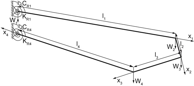
The physical model of researched system is shown in Fig. 2. The considered frame consists of four parts arranged horizontally of the bending stiffness , where respectively. The values adopted as mass per length unit were , where Furthermore it was assumed that and . The damping vibration was modeled by placing the individual hyper viscous rotary dampers supports with damping coefficient , where The beams of the frame can be mounted in an elastic, hinged or rigid way (, where – coefficient of mounting rigidity).
Fig. 2Physical model of the system
The equations of the individual beams motion of the considered frame can be written as:
The geometric boundary conditions and continuities are as following:
where 1, 2, 3.
The boundary problem is supplemented by the natural boundary conditions in the form of:
where 1, 2, 3.
4. The solution to the problem
The solutions of the Eq. (1) take the form of:
where – frequency of complex number,
By substituting Eq. (2) into Eq. (1) we obtain:
where
The boundary conditions (after the separation of variables) of considered system, are as the following:
where .
The solutions of Eq. (3) are functions:
where: .
After substituting the Eq. (6) to the boundary conditions Eq. (5), system of equations with respect to the unknown constants was obtained. In the matrix form, this system can be written as:
where: , and ,
The system of equations has a nontrivial solution if the determinant of the matrix, by constant equals zero:
As the result of the solution of boundary value problem, the vibration eigenvalues were obtained. The searched roots are complex numbers in which damped vibration frequencies are presented by the real parts while the system damping is characterized by the imaginary parts .
5. The results of the numerical computations
The length of each rod frame was 56.4, 5.6, 18.0, 43.9 [mm] and the diameter amounted 0,29, 0,25[mm]. For the calculation the dimensionless damping parameters was defined as:
In Fig. 3 the summary graphs of the dependence of the real and imaginary parts of the first eigenvalue in analysed system, relative to the structural damping parameter and mounting rigidity coefficient , were presented. The results are to be compared with the experiment
Fig. 3The dependence between the real parts (Re(ω1*)) a) and imaginary parts (Im(ω1*)) b) of the first eigenvalue and damping coefficient and the mounting rigidity coefficient in analysed system
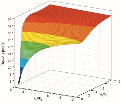
a)
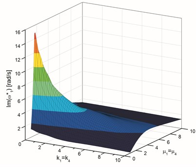
b)
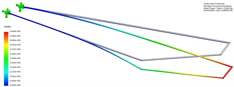
For the same geometrical and material data, additional frequency and modal shape calculations of wing-based frame were performed in SolidWorks. The results were shown in Fig. 4.
Fig. 4Modal shape of the wings support frame
6. Experimental setup and measurement technique
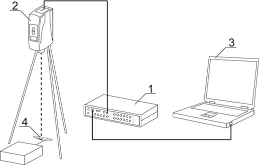
In the experiment the Pulse analyzer platform 3560C (Brüel & Kjær’s platform for noise and vibration analysis), VH-1000-D Ometron (LDV – Laser Doppler Vibrometer) and the Pulse Labshop software were used. The experimental setup is shown in Fig. 5.
Fig. 5Experimental setup: 1 – pulse analyzer platform, 2 – LDV, 3 – pulse labshop software, 4 – Mecynorrhina Torquata wing
The insect’s wing was rigidly fixed in the horizontal position. The distance between LDV and the wing amounts to 514 mm. This is the distance recommended by the manufacturer of the equipment. The laser beam was directed to the primary wing venation (,, , in Fig. 1). It should be noted that directing the laser beam to any of these veins gave the same result.
The difficulty in carrying out an experiment and building proper experimental setup was related to the fragile material of which the wing is formed. Since the wing did not bounce the sensing laser, the authors had to use a retro – reflective tape. It was attached in several places in which the measurement was made. The wing itself was firmly fixed to a brass tube, which was mounted in a heavy block. The excitation was carried out using non-destructive force excitation method with the use of impact hammer.
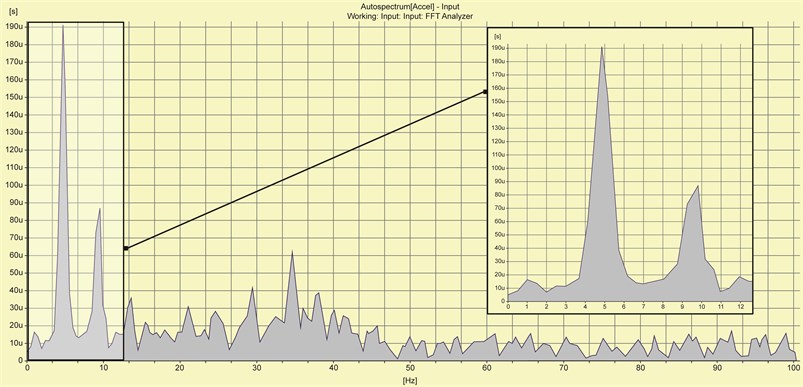
The gathered experimental data provides beetles wing vibration frequency information (Fig. 6). The previously obtained numerical results were approximately identical.
Fig. 6Vibration frequency of Mecynorhina Toruqta beetle wing
7. Conclusions
In this paper the influence of constructional damping and rigidity coefficient of mounting on the beetle wing-based frame vibrations was presented. The authors have also attempted to determine constant (within a wing) material properties that could be used in the analytical research of wing-based frame vibrations. The obtained results were used in the presented numerical computations. The experimental evaluation had initially confirmed that the adopted material properties were most similar to the original.
In the mathematical computations the authors used previously determined material properties: density 2600 [kg/m3] and Young’s modulus 0.3 [GPa]. Based on the obtained results it could be concluded that the increase both the constructional damping mounting and the mounting rigidity, causes significant changes in the frame eigenvalues. The change of the damping coefficient and the mounting rigidity coefficient greatly affects on the first eigenvalue (both on the damped frequency and the amplitude decay factor ). For any of the rigidity support value, under certain damping conditions, ( in the range from 0.9 to 1.2) one will obtain maximum decay factor.
Due to the fact that the experiment could only be conducted for the rigidly mounted wing, the mathematical and experimental results could only be compared using the value corresponding to the two-sided rigid frame mounting of mathematical model. The value of analytical research results of vibration frequency was approximately 32.7 rad/s (5.2 Hz), whereas the value obtained experimentally oscillated around 4.9 Hz. The same value of vibration frequency as in the mathematical model was obtained using SolidWorks. It can therefore be concluded that the defined material properties were valid.
In future works the authors plan to expand the wing based-frame of the Mecynorrhina Torquata beetle and continue constructional damping research in order to build an entomopter wing model.
References
-
Dudley R. The Biomechanics of Insect Flight: Form, Function, Evolution. Princeston University Press, New Jersey, 1999.
-
Kesel A. B., Philippi U., Nachtigall W. Biomechanical aspects of the insect wing: an analysis using the finite element method. Computers in Biology and Medicine, Vol. 28, 1998, p. 423-437.
-
Haas F., Gorb S., Blickhan R. The function of resilin in beetle wings. Proceedings of the Royal Society of London, Series B, Vol. 267, 2000, p. 1375-1381.
-
Wainwright S. A., Biggs W. D., Currey J. D., Gosline J. M. Mechanical Design in Organisms. Princeton University Press, 1982.
-
Sun J., Bhushan B. The structure and mechanical properties of dragonfly wings and their role on flyability. Comptes Rendus Mecanique, Vol. 340, 2012, p. 3-17.
-
Herbert R. C., Young P. G., Smith C. W., Wootton R. J., Evans K. E. The hind wing of the desert locust (Schistocerca gregaria Forskål). III. A finite element analysis of a deployable structure. The Journal of Experimental Biology, Vol. 203, 2000, p. 2945-2955.
-
Vincent J. F. V., Wegst U. G. K. Design and mechanical properties of insect cuticle. Arthropod Structure and Development – Journal, Vol. 33, 2004, p. 187-199.
-
Oliveto G., Santini A., Tripodi E. Complex modal analysis of a flexural vibrating beam with viscous end conditions. Journal of Sound and Vibration, Vol. 200, 1997, p. 327-345.
-
Sochacki W., Rosikoń P., Topczewska S. Constructional damping mounting influence on T-type frame vibrations. Journal of Vibroengineering, Vol. 15, Issue 4, 2013, p. 1866-1872.
About this article

This research was supported by the Ministry of Science and Higher Education in 2014, Warsaw, Poland.
