Abstract
Transmission noise of the magnesium alloy cylinder head cover was researched in this paper. Firstly, the numerical calculation mode of a cylinder head cover was compared with the experimental one. Results showed that the numerical calculation model had a relatively high accuracy, and it could be used in subsequent analysis. Secondly, sound pressure inside the cylinder head cover was extracted through the four-load method and taken as the sound source. Then, it was applied in a simulation model in order to simulate transmission noise of the actual situations. Afterwards, transmission noise of the magnesium alloy cylinder head cover was compared with the aluminum alloy one. It was shown that relatively low transmission noise was generated from the magnesium alloy cylinder head cover. Meanwhile, its mass was only 0.65 times of that of the aluminum alloy one. Therefore, the requirement for low noise and light weight was achieved by the magnesium alloy cylinder head cover. Then, dynamic stresses of cylinder head covers for two materials were compared. Results showed that dynamic stress of the magnesium alloy cylinder head cover was slightly smaller than that of the aluminum alloy one. The magnesium alloy cylinder head cover satisfied the requirement for strength and had a relatively prominent comprehensive performances. Finally, sound absorption coefficient of a porous material was calculated by using the numerical simulation technology. It was also laid inside the magnesium alloy cylinder head cover to constitute a composite cylinder head cover. Transmission noise of such composite cylinder head cover was much smaller than that of the original structure. This researches provided a method for low noise and light weight design of the cylinder head cover.
1. Introduction
In recent years, the global automobile industry has realized the objective of light weight by applying new materials. The traditional steel materials have been gradually replaced by light metals such as aluminum alloy and magnesium alloy as well as other composite materials. Automobile industry has become the major driving force for application of magnesium alloy [1]. Magnesium alloy material was characterized by small density, high stiffness and strength. As a result, it was suitable for vibration and noise reduction. At present, magnesium alloy has been successfully applied in the cylinder head cover. These die-casting magnesium alloy cylinder head covers have been applied by automobile companies such as GM and Benz [2]. In the near future, cylinder head covers which were made of plastic, aluminum alloy and other materials would be replaced by magnesium alloy die-casting components [3].
It was shown in many researches that the radiated noise of surface was one of main noise sources for an internal combustion engine. Cylinder head cover, oil pan and timing cover had large area and low stiffness, and they were the major radiated sources. The radiated noise generated from them occupied 40 %-60 % of the whole engine noise [4-6]. Therefore, the modern design methods such as multi-body dynamics, finite element method, and boundary element method have been widely applied in NVH research and optimization [7, 8] of thin-wall components for internal combustion engine. However, only the radiated noise of thin-wall components caused by vibration was considered in these methods. Transmission noise [9] was often neglected. In general, sound could not be thoroughly isolated by a baffle which was placed on the sound propagation path, because a part of sound waves would transmit the baffle [10]. As well, noise of the internal space which was formed by a cylinder head cover and a cylinder head would be propagated via the cylinder head cover. Hence, transmission noise of the cylinder head cover was researched in this paper.
Currently, transmission noise of a cylinder head cover could not yet be separated from the total radiated noise of engine by a experiment. Therefore, the internal sound source of the cylinder head cover was extracted by a four-load method, and then it was input into a structural-acoustic coupling simulation model. Finally, transmission noise of the cylinder head cover under the operation condition of engine was obtained. Afterwards, the original material property of the aluminum alloy cylinder head cover was replaced by magnesium alloy. Their transmission noises were calculated and compared. It was shown that the magnesium alloy cylinder head cover with the same thickness could effectively realize the objective of low noise and light weight. In addition, dynamic stress of the magnesium alloy cylinder head cover was not higher than that of the aluminum alloy one. In order to further optimize transmission noise of the magnesium alloy cylinder head cover, a composite cylinder head cover was designed.
2. Establishment and verification of the finite element model
When transmission noise of the cylinder head cover was calculated by structural-acoustic coupling method, a finite element model of structure should be established to obtain the natural frequency matrix. Therefore, a corresponding finite element model was established according to three-dimensional solid model. 10-node tetrahedron elements was adopted in the model, and it included 36,251 elements and 71,356 nodes as shown in Fig. 1. The cylinder head cover was made of casting aluminum alloy with density of 2,700 kg/m3, elasticity modulus of 75,000 MPa and Poisson’s ratio of 0.3.
Fig. 1The finite element model of the cylinder head cover
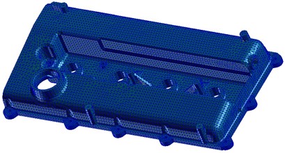
Fig. 2Test diagram of free modal
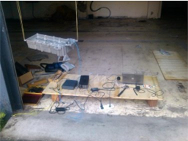
In order to verify accuracy of the finite element model, Test.Lab testing system was used to conduct modal experiment of the cylinder head cover in this paper. So as to ensure that multi-order modals of the cylinder head cover could be excited, during the experiment, a mass block was added to the force hammer head to increase frequency bandwidth of excitation signals. During the experiment, the cylinder head cover was hung by a thin rubber rope so as to simulate its free boundary. According to the geometrical shape of the cylinder head cover, 50 test points were arranged on it. Modal experiment of the cylinder head cover was shown in Fig. 2.
Modal results were compared between simulation and experiment as shown in Table 1.
It was shown that the relative errors of simulation modal were controlled within 5 %, which met the required accuracy by engineering. As a result, the simulation model was reliable and could be used in subsequent analysis.
Table 1Modal comparison of top 6 orders between simulation and experiment
Order | Experiment | Simulation | Relative error (%) |
1 | 347.08 | 352.11 | 1.45 |
2 | 532.23 | 540.27 | 1.51 |
3 | 812.86 | 804.98 | –0.90 |
4 | 998.07 | 1,008.37 | 0.65 |
5 | 1,104.30 | 1,132.21 | 2.53 |
6 | 1,190.41 | 1,201.50 | 0.93 |
3. Numerical calculation of transmission noise
Transmission noise of the cylinder head cover could not be separated from the total radiated noise during an experiment. Its transmission noise was researched in this paper by a structural-acoustic coupling method. Firstly, the boundary element model of the cylinder head cover was obtained according to the finite element model in Fig. 1. Triangular shell elements were used in the boundary element model as shown in Fig. 3. There were totally 5,689 elements and 4,867 nodes. Secondly, the boundary element model was coupled with the finite element model. A semi-spherical field point was set up on the transmission side of the cylinder head cover to observe transmission noise. The noise source was applied on the incidence side as the excitation.
Fig. 3The boundary element model of the cylinder head cover
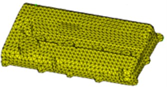
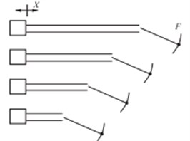
Fig. 4Principle diagram of four-load method
The external sound field of the cylinder head cover was mainly derived from the following aspects. 1) The cylinder head cover was excited by pressure fluctuation of gas which was inside the cylinder to generate vibration and noise. 2) Mechanical vibration which was caused valve opening and closing was transmitted to the cylinder head cover [11], and then it would excite the cylinder head cover to generate the radiate noise. 3) The noise of the internal space which was formed by the cylinder head cover and cylinder head was transmitted outwards. At present, there were many researches about vibration and radiation noise of the cylinder head cover, but there were few researches about transmission noise. Therefore, it was necessary to analyze it.
It was shown in practice that noise in the internal space which was formed by the cylinder head cover and cylinder head had a big sound pressure level. It exceeded range of a sensor. In addition, due to high temperature and oil splashing, its sound pressure level could not be directly measured. Hence, a four-load method experiment was used to extract the internal sound source [12, 13]. Four-load method was a common sound source extraction method with simple operations and high accuracy. The principle diagram was shown in Fig. 4.
and stood for sound pressure and impedance of the sound source, respectively. was acoustic load when was 0:
Four loads could be expressed in the following form:
Four formulas in Eq. (2) were divided in order to obtain three scale factors as shown in Eq. (3):
The transmission functions of a load at and point were calculated by simulation analysis. Sound pressure at point was converted into the sound pressure at by transmission functions. After conversion, became a known quantity. Eq. (3) could be expressed into three equalities. Then, the sound source pressure could be obtained by three equalities.
As shown in Fig. 5(a), there were four acoustic loads. During the experiment, one end of the load was connected to oil hole of the cylinder head cover, and the connection gap was sealed. A microphone was arranged at the position which was 5 cm away from the tube hole center as shown in Fig. 5(b).
An engine bench test was used to test sound pressure of the tube hole under 1,000 r/min. According to the four-load method, sound pressure level of sound source inside the cylinder head cover was obtained as shown in Fig. 6.
Fig. 5Extraction experiment of sound source by four-load method
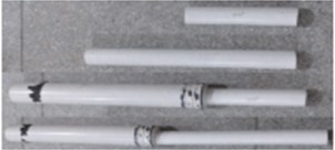
a) Four acoustic loads
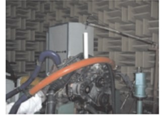
b) Experimental diagram
Fig. 6Sound pressure level of sound source
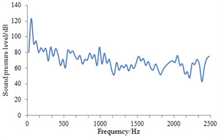
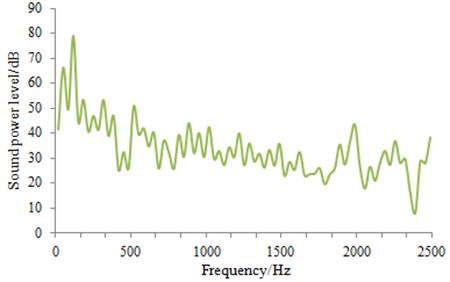
Sound pressure level of sound source in Fig. 6 was input into the structural-acoustic coupling model. Then, transmission sound power of the aluminum alloy cylinder head cover can be calculated as shown in Fig. 7.
It was shown in Fig. 7 that transmission sound power fluctuated greatly within the whole frequency band. Within the low frequency of 0 Hz-500 Hz, transmission sound power level was relatively high mainly because the sound pressure level of noise source was relatively high. Within 2,000 Hz-2,500 Hz, transmission sound power relatively increased, on one side, the sound pressure level of noise source increased, on the other side, sound within high frequency band had a relatively small wave length and could easily pass the cylinder head cover.
The aluminum alloy cylinder head cover has been applied widely, but their transmission noise was still high. Hence, this paper meant to replace it with a magnesium alloy cylinder head cover which had relatively big damping.
Fig. 7Transmission sound power of the cylinder head cover
4. Numerical calculation of transmission noise for the aluminum alloy and magnesium alloy cylinder head cover
Based on the numerical calculation model of transmission noise for the aluminum alloy cylinder head cover, transmission noise of the magnesium alloy cylinder head cover with the same thickness was researched. Afterwards, transmission noise of two kinds of cylinder head covers was compared as shown in Fig. 8.
Fig. 8Transmission noise comparison of two kinds of cylinder head covers
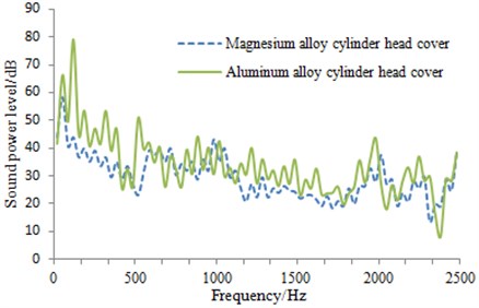
It was shown in Fig. 8 that transmission sound power of the magnesium alloy cylinder head cover was relatively smaller than that of the aluminum alloy one. It was mainly because that magnesium alloy has high damping and good attenuation characteristic. In addition, it has small atomic mass, and the internal space gap was also small, so that sound could hardly propagate through it. Under the same thickness, mass of the magnesium alloy cylinder head cover was only 0.65 times of the aluminum alloy one. Therefore, the magnesium alloy cylinder head cover realized the objective of low noise and light weight.
In actual engineering, both noise and strength should be considered. Therefore, it was necessary to analyze dynamic stresses of the aluminum alloy and magnesium alloy cylinder head covers.
5. Analysis of dynamic stresses for the aluminum alloy and magnesium alloy cylinder head covers
A cylinder head cover was fixed on the cylinder head by bolts and rubber gaskets. The explosive pressure inside the cylinder and impact from valve were directly acted on the cylinder head cover. As a result, dynamic stress of the cylinder head cover was analyzed in the following contents.
In dynamics analysis of the cylinder head cover, bolt type was M6×25, and the pre-tightening force was 8-9.3 kN. The cylinder head cover was fixed on the cylinder head by bolts and rubber gaskets. The direct contact positions between the cylinder head cover and cylinder head could be deemed to be rigid. In the meantime, elastic force from rubber gaskets was acted on the cylinder head cover. As a result, stiffness of the rubber gasket was taken into account during the finite element calculation. Rigid constraints were conducted to nodes which were used to connected the cylinder head cover and cylinder head. In addition, spring boundary conditions were loaded around the bolts to simulate effect of rubber gaskets. Dynamic stress calculation model of the cylinder head cover was shown in Fig. 9.
Through numerical calculation, dynamic stress distributions of the aluminum alloy and magnesium alloy cylinder head covers under the same operation condition were obtained as shown in Fig. 10.
Fig. 9Dynamic stress calculation model of the cylinder head cover
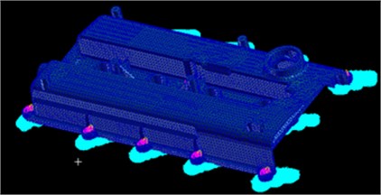
Fig. 10Dynamic stress distribution comparison of two kinds of cylinder head covers
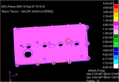
a) Dynamic stress distribution of the aluminum alloy cylinder head cover

b) Dynamic stress distribution of the magnesium alloy cylinder head cover
It was shown in Fig. 10 that the maximum dynamic stresses of the aluminum alloy and magnesium alloy cylinder head covers were 55.4 MPa and 55.2 MPa, respectively. Hence, the magnesium alloy cylinder head cover did not lead to dynamic stress increase, and strength was not decreased. It was shown in the mentioned results that the magnesium alloy cylinder head cover had prominent comprehensive performances and showed a great value in engineering applications.
6. Numerical optimization of transmission noise for the magnesium alloy cylinder head cover
It addition, it was shown in Fig. 8 that transmission noise of the magnesium alloy cylinder head cover was still high, even though there was a certain decrease in comparison with the aluminum cylinder head cover. Therefore, it was necessary to optimize transmission noise by certain measures. The traditional noise reduction measures was that structure of a cylinder head cover must be redesigned, but production cost would increase greatly due to the structural change. As a result, a sound absorption material with good heat-insulating performance was laid inside the cylinder head cover in order to design a composite cylinder head cover and reduce transmission noise.
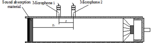
The sound absorption characteristic of material was mainly reflected by sound absorption coefficient. Sound absorption coefficient changed with frequency. Therefore, it was necessary to obtain sound absorption coefficient by certain technology and apply it into the cylinder head cover. In this paper, sound absorption coefficient of material was measured by the impedance tube method. Principles of sound absorption performance measurement with the impedance tube method was based on the transfer function method as shown in the following contents. A broadband signal was divided into an incident wave and a reflected wave . Their sizes were decided by sound pressures which were measured by two microphones installed on tubes as shown in Fig. 11. referred to distance between two microphones, and referred to distance between the second microphone and the reference surface in Fig. 11. The incident wave sound pressure and reflected wave sound pressure could be expressed by the following fomula:
where, referred to amplitude of . referred to amplitude of . referred to the wave number. Therefore, sound pressures at two microphones were expressed by the following formula, respectively:
Fig. 11Diagram of sound absorption coefficient testing with impedance tube method
Transfer function of the incident wave was shown as Eq. (8):
Transfer function of the reflected wave was shown as Eq. (9):
Transfer function of the total sound field could be obtained by and . In addition, ( referred to the reflection coefficient), so that:
Eq. (8) and Eq. (9) were combined with Eq. (10) to obtain Eq. (11):
The reflection coefficient could be determined by the measured transfer function, distance and as well as the wave number . Therefore, the sound absorption coefficient could be obtained by the following formula:
Sound absorption coefficient was obtained by the impedance tube method experiment was relatively complicated and expensive. In this paper, the simulation technology was used to simulate impedance tube experiment in order to obtain sound absorption coefficient. Simulation model was shown in Fig. 12.
Fig. 12Numerical calculation model of impedance tube
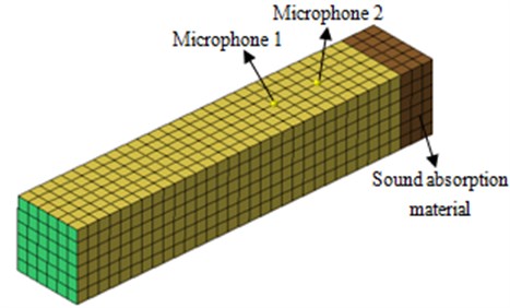
Fig. 13Sound pressure at microphone 1 and microphone 2
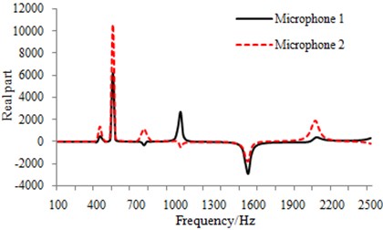
a) Real part of sound pressure
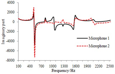
b) Imaginary part of sound pressure
The real and imaginary part of sound pressure at microphone 1 and microphone 2 were obtained by the numerical calculation model as shown in Fig. 13.
Sound pressures were substituted into the mentioned formulas. And sound absorption coefficient of the material could be obtained as shown in Fig. 14.
Fig. 14Sound absorption coefficient of material
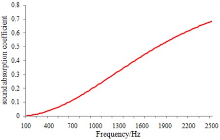
The material with a known absorption coefficient was applied into the cylinder head cover. Its transmission noise was calculated and compared with that before optimization as shown in Fig. 15.
Fig. 15Transmission noise comparison of the magnesium alloy cylinder head cover before and after optimization
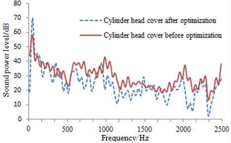
Fig. 16Transmission noise contour of the cylinder head cover before and after optimization
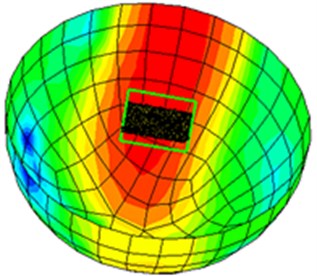
a) Transmission noise contour of the cylinder head cover before optimization
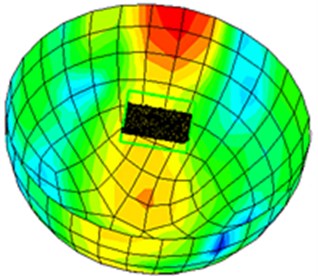
b) Transmission noise contour of the cylinder head cover after optimization
It was shown in Fig. 15 that transmission noise of the cylinder head cover was obviously reduced after using sound absorption material. In addition. sound power contour of transmission noise for the cylinder head cover under 1,000 Hz was extracted as shown in Fig. 16. It was shown that the original areas with relatively serious transmission noise were obviously improved after applying a sound absorption material layer. This result further verified that such composite cylinder head cover was very effective in transmission noise reduction.
7. Conclusions
1) The numerical calculation mode of a cylinder head cover was compared with the experimental one. Results showed that the numerical calculation model had a relatively high accuracy, and it could be used in subsequent analysis.
2) Sound pressure inside the cylinder head cover was extracted through the four-load method and taken as the sound source. Then, it was applied in a simulation model in order to simulate transmission noise of the actual situations.
3) Transmission noise of the magnesium alloy cylinder head cover was compared with the aluminum alloy one. It was shown that relatively low transmission noise was generated from the magnesium alloy cylinder head cover. Meanwhile, its mass was only 0.65 times of that of the aluminum alloy one. Therefore, the requirement for low noise and light weight was achieved by magnesium alloy cylinder head cover.
4) Dynamic stresses of cylinder head covers for two materials were compared. Results showed that dynamic stress of the magnesium alloy cylinder head cover was slightly smaller than that of the aluminum alloy one. The magnesium alloy cylinder head cover satisfied the requirement for strength and had a relatively prominent comprehensive performances.
5) Sound absorption coefficient of a porous material was calculated by using the numerical simulation technology. It was also laid inside the magnesium alloy cylinder head cover to constitute a composite cylinder head cover. Transmission noise of such composite cylinder head cover was much smaller than that of the original structure. This researches provided a method for low noise and light weight design of cylinder head cover.
References
-
Sun Q. X., Zhan Z. X., Li J. J. Current state and development prospects for magnesium alloys used in cars. Inner Mongolia Science Technology and Economy, Issue 9, 2008, p. 73-76.
-
Chen X. R., Hao Z. Y., Yang C. Simulation on sound insulation performance of an automotive dash by structure-sound interaction method. Journal of Vibration and Shock, Vol. 28, Issue 8, 2009, p. 154-157.
-
Chen L. H. Magnesium die casting alloys and their applications in automotive industry. Foundry, Issue 10, 1999, p. 45-47.
-
Pang J., Zhan G., He H. Automotive Noise and Vibration: Principle and Application. Beijing Institute of Technology Press, Beijing, 2006, p. 150-153.
-
Shu G. Q., Ma W. R., Liang X. Y. Radiation noise of external thinwall components in diesel engine. Chinese Internal Combustion Engine Engineering, Vol. 30, Issue 2, 2009¸p. 25-28.
-
Jia W. X., Hao Z. Y., Yang J. C. Research on prediction method of radiated noise of engine oil pan. Transactions of CSICE, Vol. 23, Issue 3, 2005, p. 269-273.
-
Zhang L., Ren H. J., Ai X. Y. Vibration optimization on engine covers. Journal of Vibration Engineering, Vol. 23, Issue 6, 2010, p. 687-697.
-
Loibnegger B., Rainer G., Bernard L. An integrated numerical tool for engine noise and vibration simulation. SAE Paper, Detroit, USA, 1997, p. 971-992.
-
Chen X. R. Investigation on NVH Performance of Automotive Magnesium Alloy and Acoustic Optimization Design for Magnesium Dash. Ph.D. Thesis, Department of Energy Engineering, Zhejiang University, Hangzhou, 2011.
-
Du G. H., Zhu Z. M., Gong X. F. Fundamentals of Acoustics. 2nd ed. Nanjing University Press, Nanjing, 2001.
-
Zheng X., Hao Z. Y., Jin Y. A study on the separation of valve-slap excitation and combustion excitation in IC engine using M-EEMD method. Automotive Engineering, Vol. 33, Issue 11, 2011, p. 930-936.
-
Liu C. Investigation on Engine Intake/Exhaust Noise and Design of Acoustic Simulation Platform. Ph.D. Thesis, Department of Energy Engineering, Zhejiang University, Hangzhou, 2011.
-
Jia W. X. Research on Numerical Simulation of Structural Noise/Intake Noise and Optimization Design. Ph.D. Thesis, Department of Energy Engineering, Zhejiang University, Hangzhou, 2008.
About this article

The financial supports from the National Natural Science Foundation (Grant No. 11172099) and State Key Laboratory of Advanced Design and Manufacturing for Vehicle Body (Grant No. 31415008) are acknowledged.
