Abstract
A lumped-parameter coupled nonlinear dynamic model for one large multi-stage wind turbine gearbox transmission system is established comprehensively including wind varying load, mesh stiffness, dynamic transmission error, gravity, and bearing nonlinear characteristics to obtain the gearbox dynamic response. The vibration differential equations of the drive-train are deduced through the Lagrange’s equation. On the basis of that, the dynamics of wind turbine gearbox is investigated by a Runge-Kutta numerical method that includes simultaneous internal and external excitations. The results show that the dynamic response of the partial component is mainly superposed by high-frequency component caused by the internal excitation and low-frequency component caused by the external excitation. In medium-speed stage and high-speed stage, the vibration amplitude has obvious fluctuation, and the multiple frequency and random frequency components become increasingly obvious with increasing rotational speed and eccentricity at gear and bearing positions. Axial vibrations of the system also have some fluctuation. The bearing has self-variable stiffness frequency, which should be avoided in engineering design stage. The study results provide a theoretical foundation for dynamical characteristics evaluation and dynamic optimization of a large wind turbine gearbox transmission system.
1. Introduction
The gearbox transmission plays an important role in wind power industry. A failure of the transmission may cause breakdown of the whole machinery and major economic loss. Wind turbine is being increasingly deployed in remote onshore and offshore areas due to the richer wind resource and the advantages of mitigating the land use and visual impact issues. In addition, it is complex aerodynamic, mechanical and electrical machines incorporating sophisticated control systems. Therefore, dynamic coupled vibration analysis of a large wind turbine gearbox is a key research topic in the operation and maintenance of the gearbox system, which is consist of housing, shaft, gear, support bearing and so on. The study of the vibration characteristics of individual component has been established an important part of the design. However the vibration characteristics of an individual component can change considerably when these components are assembled together to form one system, due to the coupled vibration effects among these constituent components. The gearbox is the key equipment of the synthetically mechanized wind turbine equipment, the dynamic performance impacts on the reliability and safety of the whole wind turbine. The accuracy dynamic response analysis of the wind turbine gearbox transmission is also gradually increased due to the development of power for the wind turbine train system towards the MW. Hence, the research of the coupled nonlinear dynamics an important theoretical significance and engineering application value for the large wind turbine gearbox provides. A number of models were proposed in past to describe the dynamic behavior of the wind turbine gearbox transmission system, and also achieved some remarkable achievements [1-19]. Riziotis V. A. [4] and Thomsen K. [5] established the coupled nonlinear dynamic model of a multi-stage gear-rotor-bearing transmission system by considering the internal and external excitation, and the dynamic response of the typical system is calculated and analyzed with modal superposition method. Peeters J. [6] presented three types of multi-body models for the investigation of a drive train in a wind turbine, and a comparison of the different modeling techniques is discussed for a wind turbine’s drive train with a helical parallel high speed stage, two planetary stages and a flexible rotor. Yang [7] developed an effective method for processing raw SCADA data from wind turbine, proposed an alternative condition monitoring technique based on investigating the correlations among relevant SCADA data, and realized the quantitative assessment of the health condition of a turbine under varying operational conditions. Pérez J. [8] categorized the main designs, focusing on their reliability by bringing together and comparing data from a selection of major studies due to wind turbine manufacturers are continuing to develop a range of configurations with different combinations of pitch control, rotor speeds, gearboxes, generators and converters. Tavner P. J. [9] and Zhou [10] discussed the practical methods of predicting large-wind-turbine reliability using grouped survey data from wind stats and show the turbine design, turbine configuration, time, weather and possibly maintenance can affect the extracted results. Zhu [11] and Bartelmus [12] analyzed the transmission system of gearbox used in a large-scaled wind-driven generator with application of the theory of engagement, gear system dynamics and nonlinear dynamics, and the nonlinear coupling dynamic system with multi-speed gear-driven, which includes the gears, shafts and housing, was established including time-varying stiffness, running clearance and manufacturing errors. Besides, the dynamic behaviors of the coupled system were analyzed when the internal excitation to the system was considered. Qin [13, 14] developed a mathematical model of a horizontal wind turbine drive-train by applying the flexible multi-body dynamics theory based on the Lagrange’s equation. The natural frequencies and modes were calculated, and the effects of bearing stiffness on those modes were examined. The rotational vibrations of the sun gears as well as the tooth contact forces between the sun and planet and the ring and planet were analyzed in detail. Xu [15] established the dynamic model of overall gearbox train system by lumped parameter method including the time-varying, comprehensive mesh stiffness, meshing error, and coupled vibration. But this article did not give the corresponding numerical simulation. Helsen [16-17] and John [18] focused on the gearbox model behavior assessment by means of three more complex modeling techniques of varying complexity. Both simulation and experimental results were discussed. Typical mode categories for traditional wind turbine gearboxes were defined. Moreover the challenge of the definition of an accurate approach to condense finite element models for representing the flexible components in the flexible multi-body models was overcome. Shi [19] established a mathematical model for a horizontal axial wind turbine drive-train using the torsional multi-body dynamic model. The differential equation was solved numerically by direct numerical integration, and dynamic analysis was carried out to investigate the transient response of the drive-train system. It can be seen that the references made summaries, comparison, and researches on the dynamical characteristics of the gearbox transmission system in the past, the coupled dynamic model of the gearbox system for wind turbine which considers the external load excitation, meshing stiffness, input and output torques, meshing error, nonlinear characteristics of the support bearing and gravity is rare. In order to analyze the dynamic characteristics of the gearbox transmission system more accurately, it is necessary to establish precise dynamic model of the gearbox transmission system. A requirement for reliable gearbox design calculations is sufficient insight in the dynamics of the entire wind turbine drive train.
Accurate analytical modeling, including mesh relationships and detailed characterization of the nonlinear dynamics of wind turbine gearbox, is needed to estimate gearbox vibration and predict dynamic forces in industrial applications. Little work has been done to characterize for the nonlinear effects of the support bearing and gravity on gearbox dynamics. The lack of experiment studies to understand the complex dynamics of gearbox. In this paper, characterize the complex, nonlinear dynamics of gearbox transmission system by lumped-parameter method propose an analytical model, which is systematically studied the vibration characteristics of wind turbine gearbox transmission system.
2. Dynamic model and equations of gearbox
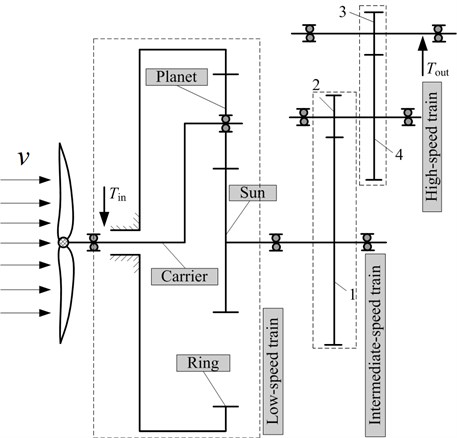
The theoretical system structure and the physical model are shown in the Fig. 1(a) and (b) respectively. The MW wind turbine gearbox transmission system that will be studied in this paper, as shown in Fig. 2, is a structural diagram that is a multi-mesh gear train. The drive-train in this study consisted of a low-speed planetary gear stage (three identical planets with spur teeth, sun and fixed ring gears) and two high-speed helical gear stages. This typical arrangement has been commonly used in the wind turbine industry.
Fig. 1The theoretical model of wind turbine gearbox

a) The basic theory of wind turbine gearbox

b) Physics model of the gear transmission system
In Fig. 2, is the input torque, represents the output torque, indicates the planet gear, is the carrier, indicates the ring gear, is the sun gear, 1 and 2 represent the driving and driven gears of intermediate-speed stage, 3 and 4 are the driving and driven gears of high-speed stage.
Fig. 2Structure diagram of wind turbine gearbox transmission
2.1. Lumped-parameter analytical model of helical gear
Considering the influence of input/output and support bearing, et al., the static model of helical gear-shaft-bearing system is shown in Fig. 3. The dynamic model of the transmission system, as shown in Fig. 4, is established. and are the equivalent mass of helical gears respectively. and represent moment of inertia; ( 1-4) is equivalent mass at bearing position. and indicate moment of inertia in input/output terminal. and represent the eccentricity. , and ( 1-4) are nonlinear bearing forces in , and directions.
Fig. 3Static model of helical gear-rotor-bearing system
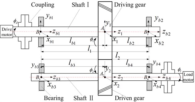
Fig. 4Dynamic mode of helical gear-rotor-bearing system
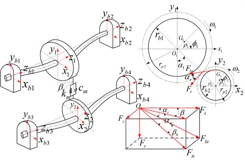
In Fig. 3, the fixed coordinate system - ( 1, 2) is set up at , which is the ideal center of the helical gears. ( 1-4) represents the ideal center of bearing. and are the geometric rotational centers of the driving and driven gears; and represent centroid respectively. To deduce kinetic equations of the helical gear-shaft-bearing system, the stress of the cylindrical gear with helical teeth should be analyzed primarily. Therefore, the dynamic model of gear meshing is shown in Fig. 4. and ( 1, 2, , ) are the rotation angle and angular vibration displacement of driving gear, driven gear, input terminal and output terminal. and are the base radius of driving and driven gears respectively; , and represent the tangential force; radial force and axial force. and are the pressure angles of the pitch circle in the end face and normal direction. and are helix angles of pitch circle and base circle. indicates the angle between center line and vertical direction.
According to the previous geometrical relationship, the angle displacements of the input/output, driving and driven gears can be expressed by the following equations:
The relationships between and the are expressed as follows:
In order to ensure the contact of teeth surface on meshing performance, it is assumed that the relative deformation of gear pair is completely changed into elastic deformation on teeth surface along with the meshing direction. The meshing gear pair is connected through the spring and damper [20]. Therefore, the comprehensive deformation of two helical gears in the meshing direction is expressed as:
Based on the viscoelasticity theory, the meshing force of gear can be described as:
where and represent the average meshing stiffness and damping; and indicate the base radius of helical gears; is the meshing error.
It is assumed that the dynamic meshing force which is from the driving gear to the driven gear is positive. So the meshing forces in , and directions can be described respectively as:
2.2. Lumped-parameter analytical model of planetary gear
The planet carrier is regarded as the input terminal, and the sun gear is the output terminal. The gear mesh is modeled as linear spring acting along the pressure line direction. The other supports/bearings are modeled as nonlinear springs. The friction forces due to gear teeth contact and other dissipative effects are captured using modal damping. Therefore the translational-rotational model of the planetary gear system is shown in Fig. 5.
Fig. 5The dynamic model of planetary transmission system
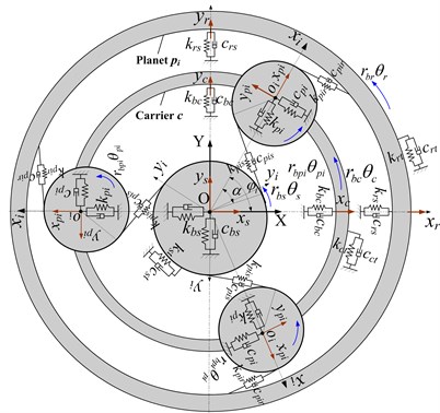
In Fig. 5, the is the fixed-coordinate system. represents the motional-coordinate system of the planet carrier. The points to the theory center of the planet gear, and the ideal angular velocity of the carrier is . , , , are the subscripts of the sun, ring, carrier and planet respectively, and the subscripts from 1 ( 1, 2, 3) designate the planets. , (, , ) represent the lateral displacements (the projections in the fixed coordinate system OXY). , ( 1, 2, 3) indicate the vibration displacements projections of the th planet gear in coordinate system. (, , , ) is the base radius of gears or radius of the carries. (, , , ) represents the rotational displacement of the sun, ring, carrier and planet respectively. Besides, it is assumed that the counterclockwise is the positive direction. is the circumferential position of the th planet around the sun gear and , is the sun-planet and ring-planet operating pressure angles. , (, , ) are the bending, torsional of sun gear and the bearing stiffness and damping in -direction and -direction respectively, , (, represent the bending of ring and the bearing stiffness and damping in -direction and -direction, , (, , ) indicate the bending, torsional of the carrier and the bearing stiffness and damping in -direction and -direction respectively, , are the th bearing stiffness and damping of planet gear in lateral-direction, , , are the mesh stiffness and damping of sun-planet and ring-planet in the pressure line direction.
2.2.1. The elastic deformation of sun-planet in the pressure line direction
In the paper , are the linear displacements of the sun gear in -direction and -direction, and the is the circumferential angular displacement. , – and – are the projections of sun-planet along the pressure line direction. , are the linear displacement of the planet gear in -direction and -direction, and the is the circumferential angular displacement. , – and – are the projections of sun-planet along the pressure line direction. So the compressive deflections in the sun-planet mesh spring can be expressed as follows:
2.2.2. The elastic deformation of ring-planet in the pressure line direction
, are the linear displacement of the ring in -direction and -direction, and the is the circumferential angular displacement. , – and – are the projections of ring-planet along the pressure line direction. , are the linear displacement of the planet gear in -direction and -direction, and the is the circumferential angular displacement. –, and are the projections of ring-planet along the pressure line direction. So the compressive deflections in the ring-planet mesh spring can be expressed as follows:
2.2.3. The relative elastic deformation between planet gear and carrier
and are the relative displacement between planet gear and carrier in the coordinate system, the elastic deformations are:
2.3. Vibration differential equations of the wind turbine gearbox transmission system
Based on the dynamic models of the helical gear and the planetary gear transmission, a generalized displacement vector of the whole gearbox transmission system can be defined with respect to the global co-ordinate system by:
where (, , , , 1, 2, 3, 4) represent the angular vibration displacement respectively, , , (, , , , 1, 2, 3, 4) are the linear vibration displacements in , , directions.
According to the dynamic analysis of the wind turbine gearbox, taking into the mesh stiffness, input/output torque, the kinetic energy , the potential energy and the dissipation function , are established of the gearbox system. Utilizing the Lagrange equation, the differential equations of the train system can be expressed as follows:
The vibration differential equation of the carrier:
The vibration differential equation of the ring gear:
The vibration differential equation of the th planet gear:
The vibration differential equation of the sun gear:
The vibration differential equation of the intermediate-speed driving gear:
The vibration differential equation of the intermediate-speed driven gear:
The vibration differential equation of the high-speed driving gear:
The vibration differential equation of the high-speed driven gear:
3. Dynamic excitation of wind turbine turbine gearbox
The gearbox transmission system withstands internal and external excitations. The external excitation mainly refers to the external influence factors, which cause the gearbox vibration. For example, the rotating blade vibration causes the gearbox vibration. The internal excitation mainly refers to gear meshing stiffness, meshing error and so on.
3.1. External excitation
According to the aerodynamic theory [21-22], taking the AR wind speed model as an external excitation, the excitation can be expressed as follows:
where is the input power of the wind turbine, represents the air density, indicates the radius of the wind turbine, is the stochastic wind speed, is power coefficient.
The input torque and output torque of the wind turbine can be expressed by the following equations:
where is the angular velocity of the wind turbine, represents the transmission ratio of the gearbox.
According to the foregoing formulas, the simulation results of the wind speed and the wind turbine input torque are shown in Fig. 6.
Fig. 6Random wind speed and driving torque
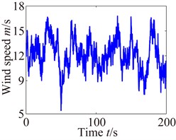
a) Waveform of wind speed
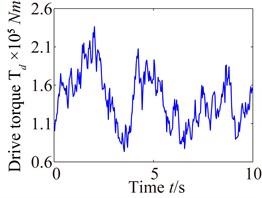
b) Waveform of input torque
3.2. Internal excitation
3.2.1. Dynamic model of the angular contact rolling bearing
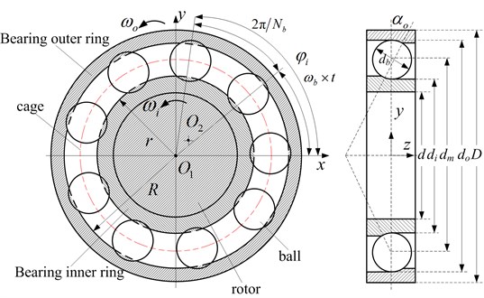
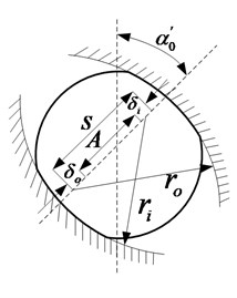
Angular contact ball bearing model is shown in Fig. 7. Bearing outer ring is fixed in bearing chock, and inner ring is fixed in shaft. The balls are uniformly distributed between outer ring and inner ring. The velocities and at the contact point between the rolling ball and outer/inner ring was analyzed, which can be expressed as:
where and represent the radius of the bearing outer and inner rings; and are the angular velocities.
Assuming that it is the pure rolling between ball and outer/inner ring, and the velocity of cage can be expressed:
Generally, the bearing inner ring rotates together with shaft, and the bearing outer ring is fixed. Utilizing the relationships 0, . So the angular velocity of the cage is as follows:
The rotation angle of the th rolling ball at moment can be expressed:
where represents the number of rolling ball.
In Fig. 7, is the diameter of rolling ball, indicates the diameter of shaft, and represent the diameters of the bearing outer and inner orbits, is the diameter of pitch circle, and .
Fig. 7Schematic diagram of angular contact rolling bearing
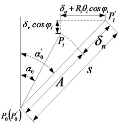
When the angular contact ball bearing is at a low speed, the centrifugal force and gyroscopic moment can be neglected. and represent the radial force and axial force of bearing respectively. The ball bearing and geometric deformation of different position are shown in Fig. 8. is the initial contacting angular of before being loaded, indicates the angular after being loaded; represents the center of the bearing outer ring before being loaded; is the one after being loaded. Because the outer ring is fixed, the and are the same position; is the center of inner ring before being loaded; represents the after being loaded; , and are the axial deformation, radial deformation and angular deformation respectively; is the curvature radius of inner orbit; is the position angular; , and represent the contacting deformation and total deformation between rolling ball and outer and inner orbits.
Fig. 8Ball bearing and deformation of different positions
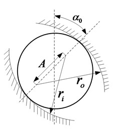
a) Before being loaded
b) After being loaded
c) Geometric deformation relation
Because the centrifugal force and gyroscopic moment are ignored, the contacting angular between rolling ball and bearing orbit and the contacting force are the same. In Fig. 8(b), the deformation of rolling ball at position angular can be expressed as:
According to geometric relationship in Fig. 8(c), the distance between the curvature center of inner orbit and outer orbit can be expressed by the following equation:
The normal contacting deformation between the th rolling ball and the bearing orbit is as follow:
Utilizing the relationships , , the Eq. (26) can be expressed by:
where and represent the linear vibration displacement respectively; ; is the initial distance between curvature center of inner orbit and outer orbit, and .
At the positon angular , the actually contacting angular can be expressed as:
According to nonlinear Hertz contact theory, the contact force between the th rolling ball and the bearing orbits is , at the same time, the normal stress can be only generated between the rolling ball and the bearing orbits when the is more than zero. So the force can be expressed by:
The normal load can be known by the Eq. (29), and the axial and radial forces can be expressed as below:
So the bearing forces (, and ) in , and directions can be expressed by:
3.2.2. Error excitation
Using the harmonic function [23], the error excitation can be described as follows:
where and represent the mean and amplitude of meshing error; is initial position angle. . indicates the tooth number of driving gear.
4. Nonlinear dynamic response of gearbox system
From the previous conclusions and results, it can be seen that the wind turbine gearbox is a complicated system with the strong nonlinearity, multi-speed gear-driven, time variance and the support bearing. Therefore it is necessary to give a detailed analysis of the wind turbine gearbox. The dynamic behaviors of system are investigated by Runge-Kutta numerical simulation method. On this basis, the gearbox geometry parameters of the transmission system analyzed in this paper are given in Table 1.
Table 1Geometric parameters of the wind gearbox transmission system
Low-speed planetary gear stage | Ring gear | Sun gear | Planet gear | Modulus | Pressure angle |
123 | 27 | 48 | 12 | 22.5 | |
Medium-speed helical gear stage | Driving gear 1 | Driven gear 2 | Normal modules | Helix angle | Pressure angle |
104 | 23 | 10 | 13.5 | 22.5 | |
High-speed helical gear stage | Driving gear 3 | Driven gear 4 | Normal modules | Helix angle | Pressure angle |
98 | 25 | 6.5 | 15 | 20 |
4.1. Dynamic response of the wind turbine gearbox
By applying the coupled vibration model of a wind turbine gearbox transmission system, the vibration analysis and calculations are carried out. In this paper, the dynamic response of the MW wind turbine gearbox with the external load excitation, meshing stiffness, input and output torques, meshing error, nonlinear characteristics of the support bearing and gravity effects are investigated using the Runge-Kutta numerical simulation method that includes simultaneous internal and external excitations. This method using the elastic mechanics theory is applied to a lumped-parameter wind turbine gearbox model. The coupled dynamic mechanical analysis of the system is performed so as to include all the components of influence factors.
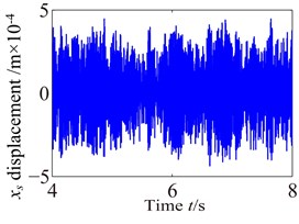
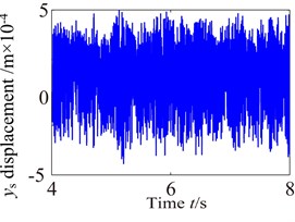
Fig. 9Vibration waveform of the planet and sun
a1)
b1)
a2)
b2)
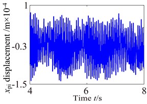
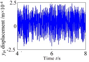
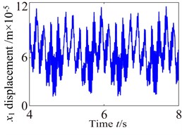
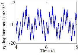
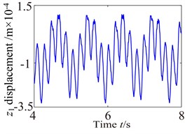
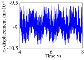
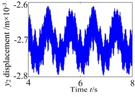
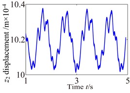
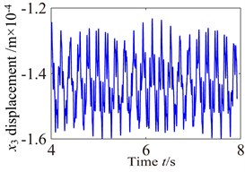
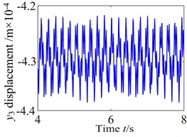
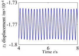
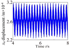
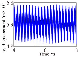
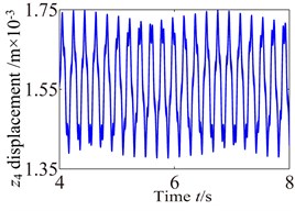
Fig. 9-Fig. 11 and Fig. 12-Fig. 14 show the vibration response of the partial component in , , directions, in which the carrier driver, having a rated speed of 17 r.p.m., drives the wind turbine gearbox to rotate. The response curves (vibration waveform and spectrum) of components are made appropriate interception in order to analyze the dynamic characteristics of the wind turbine gearbox train system more accurately. The lateral vibration displacement response of planet gear and sun gear in the low-speed stage is shown in Fig. 9. The negative value in figure indicates the opposite direction with respect to the predetermined positive direction in the model. In this paper, it can be found from comparison with Fig. 9-Fig. 11 that the planet gear has the minimum vibration amplitude, the vibration amplitude of medium-speed helical gear stage takes second place, and the vibration amplitude of high-speed helical gear stage has the maximum. In addition, the vibration waveform of each component in the train system presents a different changing trend due to the influences of the internal and external excitations.
Fig. 10Vibration waveform of the gear in medium-speed stage and high-speed stage
a1)
b1)
c1)
a2)
b2)
c2)
a3)
b3)
c3)
a4)
b4)
c4)
It can be seen from Fig. 9 that the dynamic characteristics of the planet gear and sun gear in low-speed stage become more complex due to the time-varying load and nonlinear characteristics of the support bearing. The vibration responses of the planet and sun are significant higher than others in low-speed planetary gear stage. (Because of the limited space, this paper only gives the vibration response of planet and sun). Moreover, high-harmonic components are significant shown in time-domain response. It can be found from comparison Fig. 9 with Fig. 6 that the vibration responses of the planet and sun are similar change with the external excitation.
Fig. 10 shows the lateral and axial vibration displacement responses of the medium-speed helical gear stage and high-speed helical gear stage. It can be seen from Fig. 10 that the vibration responses of driving gear in , , directions are slight higher than one of the driven gear. Comparing Fig. 10 with Fig. 9, it can be seen that the vibration response of the medium-speed helical gear stage become more complex due to the effects on the low-speed planetary gear stage and high-speed helical gear. In addition, it can be also found the low-speed stage is mainly affected by the external load, and the vibration of the high-speed stage mainly causes by load. The vibration amplitudes are also obviously increasing and the magnitude of amplitude reach the 0.1 mm due to the effects of the internal and external excitation. The support bearings in the low-speed stage and high-speed stage inevitability stand heavy dynamic load due to the effect of the gear eccentricity, mesh error and gravity. Hence, the bearing appears earlier failure. The dynamic response analysis for the wind turbine gearbox should fully be considered the influences of the bending vibration, torsional vibration, axial vibration and coupled vibration.
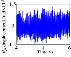
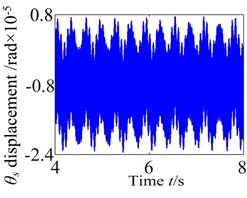
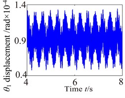
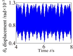
Fig. 11 shows angular vibration displacement response of the partial component. This comparison proves that the torsional vibration displacement of each component is obviously higher than those of lateral and axial vibration displacement response. So the torsional vibration is the main vibration and torsional amplitude obviously appears different vibration features due to the effects of the external excitation. In addition, the torsional vibration responses of the components appear complex vibration characteristics, which are caused by the nonlinear features of the support bearing and other excitations. In fact, bearing is one of main factor controlling vibration in a power transmission system because they play a key role in determining the system’s natural frequencies, and they can also be responsible for vibration amplification and transmission to other parts.
Fig. 11Torsional vibration of the partial component in gearbox
a)
b)
c)
d)
4.2. Frequency response of the gearbox
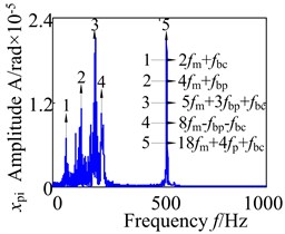
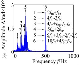
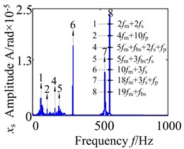
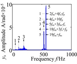
In order to accurately analyze the dynamic of the wind turbine gearbox transmission system, Figs. 12-14 show the frequency domain response of the partial component in lateral-direction, axial-direction and torsional-direction. It can be seen that the frequency domain response appear a lot of frequency multiplication and frequency combination components. The meshing frequency component of the low-speed stage is ( 29.45 Hz), medium-meshing frequency component is (163.6Hz), and the meshing frequency component of the high-speed stage (707 Hz) in the wind turbine gearbox transmission system. Fig. 12 show the lateral frequency domain response of planet gear and sun gear in the low-speed stage. Analysis of the Fig. 12(a), (b) shows that there is a certain degree of continuous spectrum at low-frequency stage due to the effects of the support bearing and the meshing between the gears, which mainly includes frequency combination ,…) and frequency multiplication. Besides, it also appears a high-harmonic component 536.5 Hz (). For the sun gear spectrum Fig. 12(c), (d), the frequency components are relatively simple, but it also appears complex frequency combination (, , ,…) and frequency multiplication. In addition to the high-harmonic component 536.5 Hz, there is also another obvious high-harmonic component 571.5 Hz (). The result indicate that the vibration frequency low-speed stage has a very obvious probability distribution, which is mainly concentrated in the frequency range below 200 Hz. This phenomenon is caused by the nonlinear characteristics of the support bearing and external excitation.
Fig. 12Lateral spectrogram of the planet and sun in gearbox
a)
b)
c)
d)
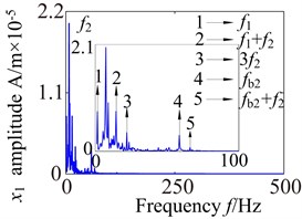
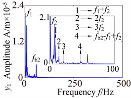
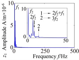
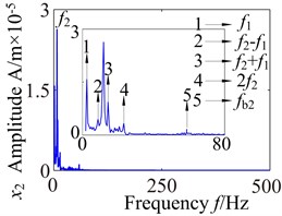
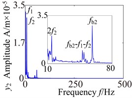
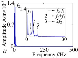
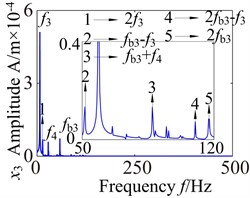
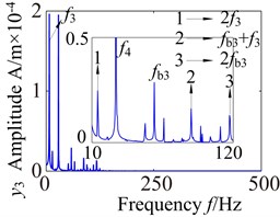
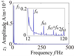
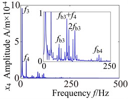
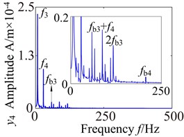
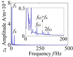
Fig. 13 shows the lateral and axial frequency domain response of the medium-speed helical gear stage and high-speed helical gear stage. It can be seen from Fig. 13 that the own rotating frequency and the rotating frequency with meshing gear are the main frequencies in , , directions. For example, the driving rotating frequency ( 1.57 Hz) and the driven rotating frequency (7.13 Hz) in medium-speed helical gear stage. The driving rotating frequency and the driven rotating frequency 28.71 Hz) in high-speed helical gear stage. The meshing frequencies ( 163.6 Hz) and ( 707 Hz) are not immediately obvious, which aren’t mark in the spectrogram.
It can be seen from the medium-speed helical gear stage that the driving shaft rotating frequency is the main frequency component in -direction and -direction, and the driven shaft rotating frequency is the main frequency component in -direction. The bearing variable stiffness frequencies (17.17 Hz) and (58.59 Hz) also appear in three directions. In addition, the frequency combination (, , , ,…) and frequency multiplication (2, 2, 2, 2,…) make the spectrogram become more complex in and directions. What’s more, the frequency components are relatively simple in direction. The rotating frequency and frequency combination are the main components and the bearing variable stiffness frequencies do not obviously appear. So the bearing has a larger effect on the lateral vibration. (High-speed train stage also has the same properties, be limited by the space restrict can’t write all go into detail).
Fig. 13Lateral and axial spectrogram of medium-speed stage and high-speed stage in gearbox
a1)
b1)
c1)
a2)
b2)
c2)
a3)
b3)
c3)
a4)
b4)
c4)
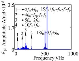
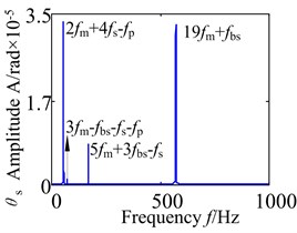
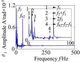
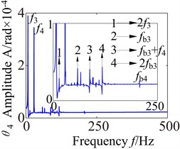
Fig. 14 shows torsional frequency domain response of the partial component in gearbox. Through the contrastive analysis, it may discover that with the increase of the speed, the amplitude distribution becomes complex gradually, where the frequency combination and frequency multiplication also appear (it is similar with the forgoing waveform). The further analysis shows that these phenomena are caused by the influences of the external excitation, the characteristics of assembly, the gear geometry parameters and the non-linear characteristics of the support bearing.
5. Conclusion
The drive-train in this study is consisted of a low-speed planetary gear stage and two high-speed helical gear stages. Based on the theory of elasticity mechanics, a lumped-parameter mathematical model is used to more precisely analyze the nonlinear dynamic model of coupled vibration for the wind turbine gearbox transmission system. The main conclusions are as follows:
1) The dynamic response of the each component in the gearbox transmission system is mainly superposed by high-frequency component caused by the internal excitation and low-frequency component caused by the external excitation. The vibration frequency of the wind power planetary gear transmission system has a very obvious probability distribution, which is mainly concentrated in the frequency range below 200 Hz.
Fig. 14Torsional spectrogram of the partial component in gearbox
a)
b)
c)
d)
2) This comparison proves that the angular vibration displacement of each component is obviously higher than those of lateral and axial vibration displacement response. So the torsional vibration is the main vibration, which is similar change with the external excitation. The planet gear has the minimum vibration amplitude, the vibration amplitude of medium-speed helical gear stage takes second place, and the vibration amplitude of high-speed helical gear stage has the maximum.
3) In medium-level and high-level transmissions, an obvious component of rotational frequency of driven shaft exists in the driving shaft due to the coupled lateral-torsional-axial vibration, and the rotating frequency and the frequency combination components are more obvious showed in torsional direction. Bearing is one of main factor controlling vibration in a power transmission system because they play a key role in determining the system’s natural frequencies, and they can also be responsible for vibration amplification and transmission to other parts. In addition, the bearing has its own variable stiffness frequency, which should be avoided in engineering system design stage.
References
-
Peeters J. L. M., Vandepitte D., Sas P. Analysis of internal drive train dynamics in a wind turbine. Wind Energy, Vol. 9, 2006, p. 141-161.
-
Peeters J. L. M. Simulation of Dynamic Drive Train Loads in a Wind Turbine. Katholieke Universiteit Leuven, Belgium, 2006.
-
Guo Y., Keller J., Parker R. Dynamic analysis of wind turbine planetary gears using an extended harmonic balance approach. ASME Conference Proceedings, Leuven, Belgium, 2012.
-
Riziotis V. A., Voutsinas S. G. Fatigue loads on wind turbines of different control startegies operating in complex terrain. Journal of Wind Engineering and Industrial Aerodynamics, Vol. 85, 2000, p. 211-240.
-
Thomsen K., Poul S. Fatigue loads for wind turbines operating in wakes. Journal of Wind Engineering, Vol. 80, 1999, p. 121-136.
-
Peeters J., Vandepitte D., Sas P. Flexible multibody model of a three-stage planetary gear-box in a wind turbine. Proceedings of ISMA, Vol. 165, 2004, p. 3923-3942.
-
Yang W. X., Court R., Jiang J. S. Wind turbine condition monitoring by the approach of SCADA data analysis. Renewable Energy, Vol. 53, 2013, p. 365-376.
-
Pérez J. M. P., Márquez F. P. G., Tobias A. Wind turbine reliability analysis. Renewable and Sustainable Energy Reviews, Vol. 23, 2013, p. 463-472.
-
Tavner P. J., Xiang J., Spinato F. Reliability analysis for wind turbines. Wind Energy, Vol. 10, Issue 1, 2007, p. 1-18.
-
Zhou Z. G., Qin D. T., Yang J., et al. Gear-bearing coupling dynamics characteristics of wind turbine planetary gear transmission system under variable load. Journal of Chongqing University, Vol. 35, 2012, p. 7-14.
-
Zhu C. H., Huang Z. H., Tang Q., et al. Analysis of nonlinear coupling dynamic characteristics of gearbox system about wind-driven generation. Chinese Journal of Mechanical Engineering, Vol. 41, 2005, p. 203-207.
-
Bartelmus W., Zimroz R. Vibration condition monitoring of planetary gearbox under varying external load. Mechanical Systems and Signal Processing, Vol. 23, 2009, p. 246-257.
-
Qin D. T., Gu X. G., Wang J. H. Dynamic analysis and optimization of gear trains in a megawatt level wind turbine. Journal of Chongqing University, Vol. 32, 2009, p. 408-414.
-
Qin D. T., Wang J. H., Lim T. C. Flexible multibody dynamic modeling of a horizontal and turbine drive train system. Journal of Sound and Vibration, Vol. 329, 2010, p. 3565-3586.
-
Xu Q., Chen C. Z. The model for dynamic of wind turbine gear transmission system. Journal of Vibration and Shock, Vol. 29, 2009, p. 7-12.
-
Helsen J., Vanhollebeke F., Marrant B. Multi-body modeling of varying complexity for modal behavior analysis of wind turbine gearboxes. Renewable Energy, Vol. 36, 2011, p. 3098-3113.
-
Helsen J., Vanhollebekeb F., Conincka F. D., et al. Insights in wind turbine drive train dynamics gathered by validating advanced models on a newly develop 13.2 MW dynamically controlled test-rig. Mechatronics, Vol. 21, 2011, p. 737-752.
-
John F. H., Christine A. M., et al. Wind energy conversion with a variable ratio gearbox design and analysis. Renewable Energy, Vol. 36, 2011, p. 1075-1080.
-
Shi W., Kim C. W., Chung C. W., Park H. C. Dynamic modeling and analysis of a wind turbine drive-train using the torsional dynamic model. International Journal of Precision Engineering and Manufacturing, Vol. 14, 2013, p. 153-159.
-
Dou W., Zhang N., Liu Z. S. The coupled bending and torsional vibrations of the high-speed geared rotor-bearing system. Journal of Vibration Engineering, Vol. 24, 2011, p. 385-393.
-
Lmi T. C., Cheng Y. A theoretical study of the effect of pinion offset on the dynamics of hypoid geared rotor system. Transactions of the ASME, Journal of Mechanical Design, Vol. 121, 1999, p. 535-539.
-
Liu C. Y., Wang W. S., Zhao H. X., et al. Induction Generators for Wind Power. China Electric Power Publishing House, Beijing, Vol. 8, 2009, p. 42-47.
-
Li R. F., Tao Z. G., Lin T. J., et al. Numerical simulation for inner dynamic excitation of gearing. Journal of Mechanical Transmission, Vol. 25, 2001, p. 1-3.
About this article
The project was supported by China Natural Science Funds (No. 51475084).
