Abstract
This paper concerns a global stabilization problem for an -TORA (Translational Oscillator with a Rotational Actuator) system which consists of n carts connected to the fixed walls and each other by linear springs with each cart having an eccentric rotational proof-mass actuator moving in the horizontal plane. First, this paper derives the motion equation of the -TORA system. Then, by using Lyapunov stability theory and physical properties of mechanical parameters of the -TORA system, this paper proves that the global stabilization of the -TORA system can be achieved by the PD control of the angle of the rotational proof-mass of each TORA. This paper presents numerical simulation results for 2- and 3-TORA systems to validate the result of the global stabilization.
1. Introduction
In the last two decades, there has been a lot of interest in the control design and analysis of underactuated systems, defined as mechanical systems in which the dimension of the configuration space exceeds that of the control input space; that is, with fewer control inputs than degrees of freedom. The TORA (Translational Oscillator with a Rotational Actuator) system which is a simplified model of a dual-spin spacecraft for investigating the resonance capture phenomenon, has been proposed as a benchmark problem for nonlinear system design [1, 2]. Since the translational position of the cart is unactuated, the TORA system has also been studied as a typical example of underactuated systems.
The global stabilization problem of the TORA system has attracted many researchers [1, 3-7]. It was shown that the TORA system is globally stable under the PD control of the angle of the rotational proof-mass [8]. A system consisting of rotor-type oscillators mounted on a straight-line spring-mass system was proposed in [9] to investigate self-synchronized phenomena which are found in mechanics, electricity, chemistry, and biology [10], where each unit of the rotor-type oscillator is the same with the rotor moving in the vertical plane.
Motivated by the above researches, in this paper, we concern an -TORA system consisting of -TORAs with a spring connecting two neighboring TORAs (Fig. 1), and we study the global stabilization problem for a general -TORA system in which all TORAs are not assumed to be the same rather than the synchronization problem. To the best of our knowledge, such a stabilization problem has not been studied. First, this paper derives the motion equation of the TORA system. Then, by using Lyapunov stability theory and physical properties of mechanical parameters of the -TORA system, we prove that the global stabilization of the -TORA system can be achieved by the PD control of the angle of the rotational proof-mass of each TORA.
The remainder of this paper is organized as follows: Section 2 presents the motion equation of the -TORA system. Section 3 derives a PD controller for the global stabilization and presents a global motion analysis of the -TORA system under the derived PD controller. Section 4 gives numerical simulation results for 2- and 3-TORA systems, and Section 5 makes some concluding remarks.
2. Motion equation of -TORA system
We consider the -TORA system (Fig. 1) consists of carts connected to the fixed walls and each other by linear springs with each cart having an eccentric rotational proof-mass actuator moving in the horizontal plane. All carts are constrained to have one-dimensional travel in the horizontal plane.
Fig. 1n translational oscillators with n rotational actuators: an n-TORA system

For the th TORA (Fig. 2), is the translational position of the th cart, is the angular position of the rotational proof-mass, is the spring stiffness, is the cart mass, is the eccentric mass, is the distance between eccentricity and axis of rotation (AOR), is the moment of inertia around the AOR, and denotes the control torque applied to the rotational proof-mass.
Fig. 2ith translational oscillator with ith rotational actuator
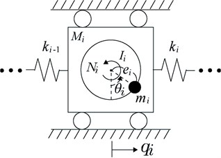
Below, we derive the motion equation for the -TORA system by using the Euler-Lagrange equation [11]. The total kinetic energy of the -TORA system is:
where is the total kinetic energy of the th TORA. To obtain, we express (), the coordinates of the th actuator as:
can be expressed as:
where is the translational kinetic energy of the th cart, is the translational kinetic energy of the th actuator, and is the rotational kinetic energy of the th actuator. Direct computation yields:
Let us consider the potential energy of the -TORA system. We obtain:
where .
The Lagrangian function of the -TORA system is:
Using the Euler-Lagrange equation for , and expressed below:
yields:
Thus, we obtain:
which yields:
From Eq. (1) and Eq. (5), the total mechanical energy of the -TORA system, , satisfies:
A property of the -TORA system is:
To show this, one can compute directly by using Eq. (9). An alternative and direct way is to use on the principle of virtual work [11] to obtain:
where is small variation of and is small variation of . Dividing two sides of Eq. (12) by and taking , we obtain Eq. (11).
3. PD control for global stabilization
Define:
The control objective is to stabilize the -TORA system to the origin ; that is, to design () such that:
We provide the following theorem about the global motion analysis of the -TORA system under the PD controllers.
Theorem 1. Consider the -TORA system given in Eq. (9). Under the PD controller:
where and are positive constants, Eq. (15), (16) hold for any initial condition of the -TORA system in Eq. (9); that is, the global asymptotical stabilization is achieved.
Proof. Take the following Lyapunov function candidate:
where each is a positive constant. Using Eq. (11) and taking the time derivative of along Eq. (9), we obtain:
Using Eq. (17) yields:
Now, we use LaSalle’s invariant principle [12] to analyze the motion of the closed-loop system consisting of Eq. (9) and Eq. (17). To this end, we need to define a compact set that is positively invariant with respect to the closed-loop system. Under controller Eq. (17), owing to in Eq. (20), is bounded. This shows that and are bounded. Since in Eq. (10) is bounded, so , , and are bounded. Define:
where is a positive constant. Then any closed-loop solution starting in remains in for all . Let be the largest invariant set in:
Using LaSalle’s invariant principle, we know that every starting in approaches as . Since holds identically in , is a constant in , and from Eq. (20) we can see that holds in and is also a constant in denoted as .
From Eq. (17) with and , we conclude that is a constant in denoted as . Putting and into Eq. (9) and Eq. (17) yields:
Integrating Eq. (25) with respect to time gives:
where is a constant. Since is bounded due to the boundedness of in Eq. (10) and since Eq. (26) holds for all , we conclude that:
must hold; otherwise there is a contradiction since the left-side term of Eq. (26) is bounded while the right-side term is unbounded as . With Eq. (23), we have . This shows that holds in ; that is, Eq. (16) holds.
Putting Eq. (27) and into Eq. (25), we have , which yields:
where and are constants. Since in Eq. (10) is bounded, from the boundedness of in the left-hand side of the above equation, we can see ; otherwise, the absolute value of the right-hand side of the above equation goes to infinity as . Thus, is a constant denoted as . Thus, from Eq. (24), we obtain:
Writing out Eq. (29) with yields:
where:
Perform column manipulation to delete in (1, 2) of yields the following matrix:
where:
Thus:
where:
From the above relation, by performing the above column manipulation repeatedly, we can obtain:
where:
Thus, in Eq. (32) is an invertible matrix. From Eq. (30), we have:
This shows that holds in ; that is, Eq. (15) holds. This completes the proof of Theorem 1.
We present the following two remarks:
Remark 1. Theorem 1 shows that the global stabilization of -TORA system given in Eq. (9) can be achieved by using the PD control of the angle of the rotational proof-mass of each TORA. This means that the local control of each TORA (using the angular position and velocity of each TORA) yields the global stabilization of the whole system.
Remark 2. The fact that in Eq. (32) determined by all springs is an invertible matrix is important in the proof of Theorem 1. We can show that the PD control can globally stabilize the -TORA system with and/or ; that is, the spring (respectively, springs) connected to one side (respectively, two sides) of the wall (respectively, walls) of the -TORA system is (respectively, are) absent. Indeed, from Eq. (37), we can show that for and/ or .
4. Numerical simulation results
The validity of the developed theoretical results was verified via numerical simulation investigation for 2- and 3-TORA systems.
4.1. 2-TORA system
First, we took the mechanical parameters in [2] shown in Table 1 for TORA 1 and took different mechanical parameters for TORA 2, and the stiffness of each spring is described as: 186.3 N/m, 100.3 N/m, 186.3 N/m.
It was mentioned in [2] that the physical constraint of displacement of the cart is its absolute value not greater than 0.025 m. Thus, we took an initial condition , 1, 2, and we chose the control gains 0.08, 0.07, 0.002, 0.001. The simulation results of the PD control are shown in Figs. 3-6. From Fig. 3, we can see that is non-increasing; from Figs. 5-6, we can see that the state variables of the -TORA system converge to the origin.
Table 1Mechanical parameters of a 2-TORA system
TORA | TORA 1 | TORA 2 |
[kg] | 1.3608 | 0.8608 |
[kg] | 0.096 | 0.056 |
[m] | 0.0592 | 0.0392 |
[kg∙m2] | 0.0002175 | 0.0001175 |
Fig. 3Time response of V of the 2-TORA system
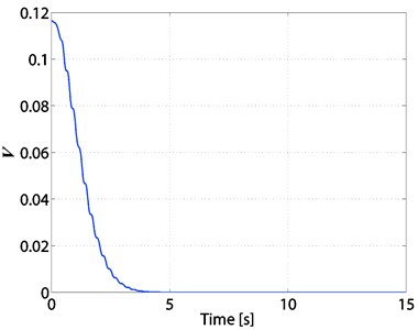
Fig. 4Time responses of N1and N2 of the 2-TORA system
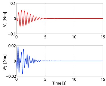
Fig. 5Time responses of q1 and q2 of the 2-TORA system
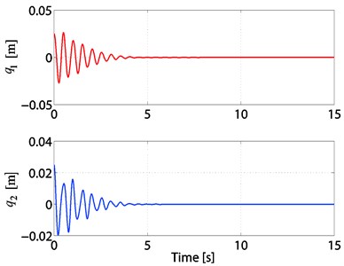
Fig. 6Time responses of θ1and θ2 of the 2-TORA system
4.2. 3-TORA system
We took the mechanical parameters shown in Table 2 and the stiffness of each spring is described as: 186.3 N/m, 100.3 N/m, 130.3 N/m, and 160.3 N/m.
Table 2Mechanical parameters of a 3-TORA system
TORA | TORA 1 | TORA 2 | TORA 3 |
[kg] | 1.3608 | 0.8608 | 0.5608 |
[kg] | 0.096 | 0.056 | 0.036 |
[m] | 0.0592 | 0.0392 | 0.0192 |
[kg⋅m2] | 0.0002175 | 0.0001175 | 0.00009175 |
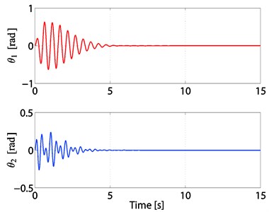
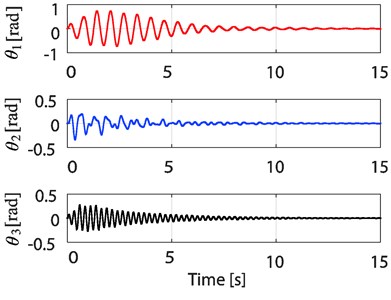
For an initial condition , 1, 2, 3 and we chose the control gains 0.055, 0.055, 0.055, 0.001, 0.001, 0.0004. The simulation results of the PD control are shown in Figs. 7-10. From Fig. 7, we can see that is non-increasing; from Figs. 9-10, we can see that the state variables of the 3-TORA system converge to the origin.
By comparing the simulation results for the 2 and 3-TORA systems, we find that it takes more time to suppress the oscillation in the system as the number of TORAs increases.
Fig. 7Time response of V of the 3-TORA system
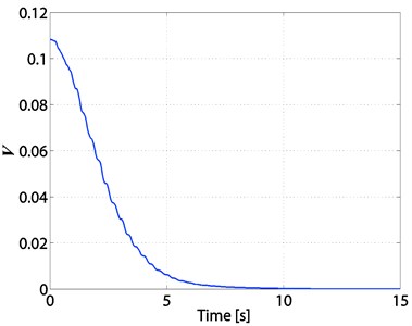
Fig. 8Time responses of N1, N2, and N3 of the 3-TORA system
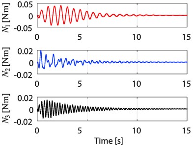
Fig. 9Time responses of q1, q2, and q3 of the 3-TORA system
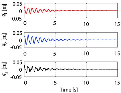
Fig. 10Time responses of θ1, θ2, and θ3 of the 3-TORA system
5. Conclusions
In this paper, we studied the global stabilization problem of an -TORA system consisting of TORAs with a spring connecting two neighboring TORAs. First, we derived the motion equation of the -TORA system. Then, by using Lyapunov stability theory, we designed the PD controller and proved that the proposed PD controller can globally stabilize the -TORA system. Finally, we presented the simulation results for 2- and 3-TORA systems to validate the effectiveness of the proposed controller. Our numerical investigation showed that the proposed controller can stabilize the 2- and 3-TORA systems to the equilibrium point for the all initial conditions simulated.
A future research subject is to study the relationship between the rate of convergence to the origin and the values of the control gains.
References
-
Wan C. J., Bernstein D. S., Coppola V. T. Global stabilization of the oscillating eccentric rotor. Nonlinear Dynamics, Vol. 10, Issue 1, 1996, p. 49-62.
-
Bupp R. T., Bernstein D. S., Coppola V. T. A benchmark problem for nonlinear control design. International Journal of Robust and Nonlinear Control, Vol. 8, 1998, p. 307-310.
-
Escobar G., Ortega R., Sira-Ramirez H. Output-feedback global stabilization of a nonlinear benchmark system using a saturated passivity-based controller. IEEE Transactions on Control Systems Technology, Vol. 7, Issue 2, 1999, p. 289-293.
-
Jankovic M., Fontaine D., Kokotovic P. V.TORA example: cascade-and passivity-based control designs. IEEE Transactions on Control Systems Technology, Vol. 4, Issue 3, 1996, p. 292-297.
-
Karagiannis D., Jiang Z. P., Ortega R., Astolfi A. Output-feedback stabilization of a class of uncertain non-minimum-phase nonlinear systems. Automatica, Vol. 41, Issue 9, 2005, p. 1609-1615.
-
Celani F. Output regulation for the tora benchmark via rotational position feedback. Automatica, Vol. 47, Issue 3, 2011, p. 584-590.
-
Ye H. Saturated delayed controls for feedforward nonlinear systems. IEEE Transactions on Automatic Control, Vol. 59, Issue 6, 2014, p. 1646-1653.
-
Tsuda T., Xin X., Yamasaki T. Global stabilization control of a translational oscillator with a rotational actuator. Proceedings of the 53rd Japan Joint Automatic Control Conference, 2010, p. 262-265.
-
Mori H., Bonkobara Y., Kondou T., Ayabe T. Self-synchronized phenomena generated in rotor-type oscillators: investigation using nonlinear normal modes. Journal of System Design and Dynamics, Vol. 2, Issue 3, 2008, p. 874-885.
-
Pikovsky J. K. A., Rosenblum M. Synchronization: A Universal Concept in Nonlinear Sciences. Cambridge University Press, Cambridge, 2003.
-
Goldstein H., Poole C., Safko J. Classical Mechanics. Third Edition. Addison-Wesley, Boston, 2001.
-
Khalil H. K. Nonlinear Systems. Third Edition. Prentice-Hall, New Jersey, 2002.
About this article
This work was supported in part by JSPS KAKENHI Grant Number 26420425.
