Abstract
The rubber floating-slab track is one of the best methods to isolate vibration induced by the interaction of the train and the rails. In order to improve its vibration reduction ability, three kinds of supporting forms, i.e. full-surface supporting, linear supporting and point-like supporting, were discussed by laboratory tests. Through time history analysis and frequency spectrum analysis, we found that the linear supporting form and the point-like supporting form have the smaller first resonant frequency than the full-surface supporting form, which is induced by the weakened supporting stiffness. Because of this reason, the maximum values of vibration acceleration of the floating slab for the linear supporting form and the point-like supporting form increase in the time domain and the frequency domain. However, the point-like supporting form has the smallest transfer ratio of vibration acceleration from the floating slab to the tunnel wall compared with the linear supporting form and the full-surface supporting form.
1. Introduction
Vibration generated by underground railways is one of the most serious engineering problems. Waves induced by the dynamic interaction between the train wheels and the rails propagate from the surrounding soil to the foundations of nearby buildings, resulting in structural vibrations and re-radiated noise. Considering this problem, many vibration reduction products have been used, e.g. the Pandrol Vanguard [1], the Cologne Egg [2], the ladder track [3] and the floating slab track [4]. The floating-slab track is the best method to isolate vibration from underground railways [5, 6], which can be supported by rubber bearings, glass fiber or steel-springs [7]. In this paper, the focus is the rubber floating-slab track.
In the last decades, many researchers have devoted themselves to the dynamical research of rubber floating-slab tracks. Geng, et al. [8] constructed a 3D finite element model to analyze the normal models of the rubber floating-slab track. Eigenfrequencies of the floating slab with two densities were analyzed under different rubber bearing stiffness and fastener stiffness. Zou, et al. [9, 10] investigated the dynamic responses of vertical vibration of the rubber floating slab tracks with floating-slab thickness, fastener stiffness and rubber bearing stiffness by the multi-rigid dynamical model of the vehicle and the rubber floating-slab track. Xu, et al. [11] studied the vibration effect of the rubber floating-slab track with 3 different kinds of slab lengths and 5 different kinds of rubber stiffness by the train-track-tunnel model. Similarly, Cui, et al. [12] used the train-track-foundation model to analyze the vibration isolation effect of the rubber floating-slab track with different spacing, stiffness and damping of rubber bearings. Furthermore, Saurenman and Phillips [13] tested the rubber floating slab track used on the current San Francisco Bay Area Rapid Transit (BART) system. The results showed that the floating slabs performed much as designed. Hwang, et al. [14] performed a laboratory mock-up test to understand the dynamical behaviors of the rubber floating-slab track more accurately. Besides these, Montella, et al. [15] introduced an innovative floating-slab track supported by recycled rubber bearings. This track was studied in different configurations by the numerical model validated by an exhaustive experiment. Wu, et al. [16] researched the physical deterioration of rubber bearings affected by air oxidation, ozone ageing and the random fatigue loads by the test.
The present contribution aims to assess vibration reduction ability of the rubber floating-slab track with different supporting forms by the laboratory test. This paper is organized as follows. Section 2 introduces the experiment platform. Then, different supporting forms are represented in Section 3. In Section 4, the experiment plan is described. Vibration reduction ability of the rubber floating-slab tracks is assessed by time history analysis and frequency spectrum analysis in Section 5. Conclusions are in Section 6.
2. Experiment platform
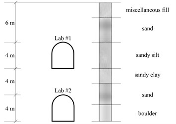
Track vibration abatement and control laboratory of Beijing Jiaotong University is an underground two-story structure to research track vibration, which is the only one in Asia. The laboratory is made up of two experiment platforms, i.e. Lab #1 and Lab #2. The covering earth depth of Lab #1 is 6 m. The covering earth depth of Lab #2 is 14 m. Fig. 1 shows the earth condition around the laboratory.
Fig. 1Cross section of the laboratory
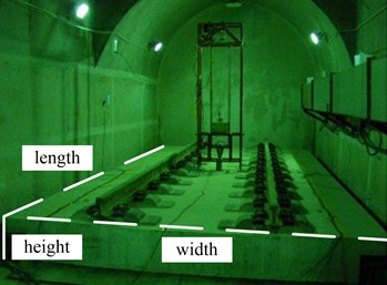
The tested rubber floating-slab track is located in Lab #1. The minimum distance between the tunnel wall and the floating concrete slab is 0.25 m. The minimum distance between the tunnel face and the floating concrete slab is 0.5 m. Fig. 2 shows the detailed sizes of the rubber floating-slab track and Lab #1. Fig. 3 is a photo of the tested rubber floating-slab track pictured in Lab #1.
Fig. 2Demonstration of the tested rubber floating-slab track in Lab #1
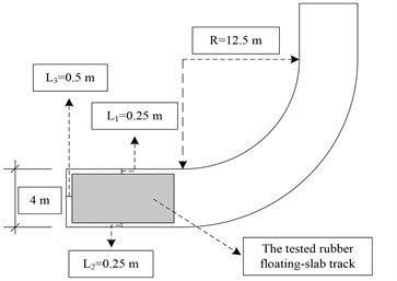
Fig. 3The tested rubber floating-slab track pictured in Lab #1
3. Different supporting forms
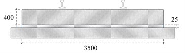
The size of the tested floating concrete slab in Lab #1 is 7000 mm (length) × 3500 mm (width) × 400 mm (height). There are two 60 kg/m rails fixed by 20 fasteners on the floating slab, see Fig. 3. Nowadays, there is only one supporting form for the floating-slab track in China, i.e. full-surface supporting. Therefore, the size of the rubber bearing in full-surface supporting form is 7000 mm (length) × 3500 mm (width) × 25 mm (height), according to the size of the tested floating concrete slab in Lab #1. Fig. 4 demonstrates the size of the floating-slab track with full-surface supporting. The volume of the rubber bearing is 0.6125 m3.
Fig. 4The rubber floating-slab track with full-surface supporting (unit: mm)
In order to improve vibration reduction ability of the rubber floating-slab track, linear supporting and point-like supporting are designed for the floating-slab track based on a lot of numerical analysis.
There are two pieces of rubber mats in linear supporting form. The size of one rubber mat is 7000 mm (length) × 250 mm (width) × 25 mm (height), Fig. 5 shows the details. The volume of two rubber mats is 0.0875 m3. Compared with full-surface supporting, material usage of linear supporting is reduced to 14.3 %.
Furthermore, 12 rubber pads in total are used for the rubber floating-slab track with point-like supporting. Fig. 6 shows the positions of the rubber pads. The Size of one rubber pad is 400 mm (length) ×375 mm (width) × 25 mm (height). Consequently, the volume of all rubber pads is 0.045 m3. Compared with full-surface supporting, material usage of point-like supporting is reduced to 7.3 %.
Fig. 5The rubber floating-slab track with linear supporting (unit: mm)
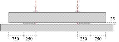
a) Cross section
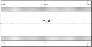
b) Plan
Fig. 6The rubber floating-slab track with point-like supporting (unit: mm)
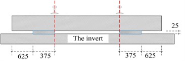
a) Cross section
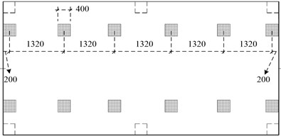
b) Plan
4. Experiment plan
There were two kinds of vibration acceleration sensors in this test. First one was 20 g ICP vibration acceleration sensor, which was fixed on the floating slab for acquiring vertical vibration acceleration of the floating slab. Second one was 3 g ICP vibration acceleration sensor, which was fixed to the tunnel wall for acquiring vertical vibration acceleration of the tunnel wall. INV3018C from China Orient Institute of Noise and Vibration was used to acquire the vibration signal.
In order to avoid testing errors, sensors were fixed on two sides of the floating slab and the tunnel. #1 and #2 were fixed on the floating slab. #3 and #4 were fixed on the tunnel wall. The distance between the sensor on the tunnel wall and the rail head is 0.8 m. Fig. 7 shows the detailed positions of the sensors. The sampling frequency of the vibration acceleration signal was set 1600 Hz.
Fig. 7Sensor positions
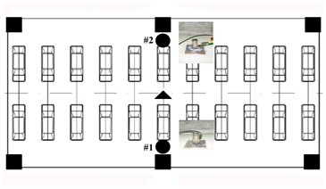
a) Plan (▲ is forced by the automatic dropping hammer device, 20 g ICP vibration acceleration sensors are fixed on ●, ■ are supported by jacks)
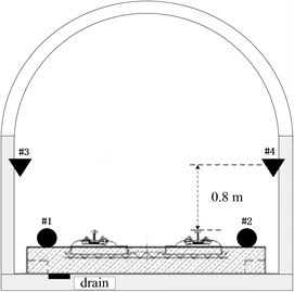
b) Cross section (3 g ICP vibration acceleration sensors are fixed on ▼, which is 0.8 m far from the rail head)
The automatic falling weight machine, shown in Fig. 8, was employed to impulse the floating slab as the vibration source. By changing the number of mass blocks and the dropping height, different impulse forces can be obtained. The material of the hammer head can also be changed by aluminum, rubber, nylon and steel.
Fig. 8The automatic dropping hammer device
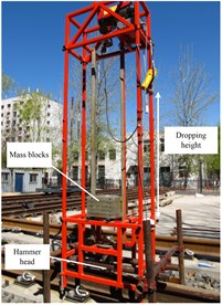
In this test, five mass blocks, about 73 kg in total, were installed. The aluminum hammer head was used and the drop height was set 10 cm. A force sensor is installed in the hammer head. The impulse position is the center of the floating slab, see Fig. 7. The sampling frequency of the force signal was set 12.8 kHz.
5. Vibration analysis
5.1. Time history analysis
According to the data of the vibration acceleration signal, the time history of the floating slab and the tunnel wall can be obtained. Fig. 9 shows the time history of vertical vibration acceleration at #1, #2, #3 and #4 for the rubber floating-slab track with full-surface supporting. #1 has the maximum (absolute) vertical vibration acceleration 0.509 g of the floating slab. #2 has the maximum value 0.568 g. #1 and #2 almost have the same vibration characteristics. #3 has the maximum (absolute) vertical vibration acceleration 0.00182 g of the tunnel wall. #4 has the maximum value 0.0029 g. From Fig. 9(c) and Fig. 9(d), it’s obvious that vibration acceleration of two sides of the tunnel wall is different. According to the experimental environment, the difference happened with a drain near the left foot of the tunnel wall where #3 fixed. The drain here attenuated the wave propagating from the floating concrete slab.
Fig. 9Time history of vertical vibration acceleration of the floating slab and the tunnel wall for the floating-slab track with full-surface supporting
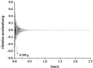
a) Time history of vertical vibration acceleration at #1
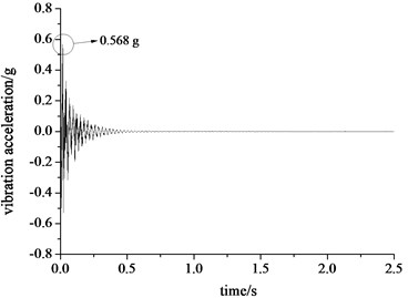
b) Time history of vertical vibration acceleration at #2
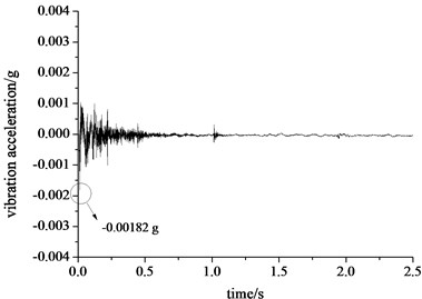
c) Time history of vertical vibration acceleration at #3
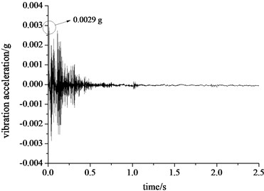
d) Time history of vertical vibration acceleration at #4
Fig. 10 shows the time history of vertical vibration acceleration at #1, #2, #3 and #4 for the rubber floating-slab track with linear supporting. #1 has the maximum vertical vibration acceleration 0.976 g. #2 has the maximum value 1.013 g. Furthermore, #3 has the maximum (absolute) vertical vibration acceleration 0.0027 g on the tunnel wall. #4 has the maximum (absolute) value 0.009 g. It’s obvious that the linear supporting form makes the maximum value of vertical vibration acceleration bigger than the full-surface supporting forms. Moreover, the oscillating time of the floating concrete slab in linear supporting form is longer than the full-surface supporting form. It is induced by the weakened supporting stiffness.
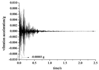
Fig. 11 shows the time history of vertical vibration acceleration at #1, #2, #3 and #4 for the rubber floating-slab track with point-like supporting. #1 has the maximum vertical vibration acceleration 0.884 g of the floating slab. #2 has the maximum value 0.911 g. Furthermore, #3 has the maximum vertical vibration acceleration 0.00591 g on the tunnel wall. #2 has the maximum (absolute) value 0.00885 g. Like the linear supporting form, the point-like supporting form has a bigger peak value of vertical vibration acceleration than the full-surface supporting forms.
Fig. 10Time history of vertical vibration acceleration of the floating slab and the tunnel wall for the floating-slab track with linear supporting
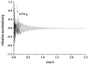
a) Time history of vertical vibration acceleration at #1
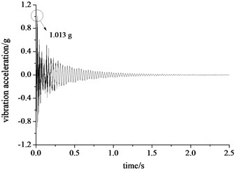
b) Time history of vertical vibration acceleration at #2
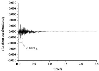
c) Time history of vertical vibration acceleration at #3
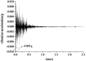
d) Time history of vertical vibration acceleration at #4
Fig. 11Time history of vertical vibration acceleration of the floating slab and the tunnel wall for the floating-slab track with point-like supporting
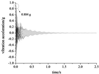
a) Time history of vertical vibration acceleration at #1

b) Time history of vertical vibration acceleration at #2
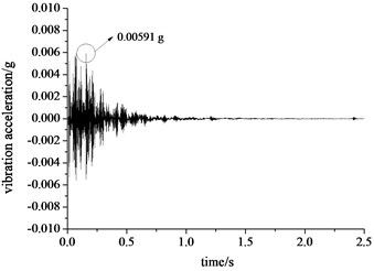
c) Time history of vertical vibration acceleration at #3
d) Time history of vertical vibration acceleration at #4
5.2. Frequency spectrum analysis
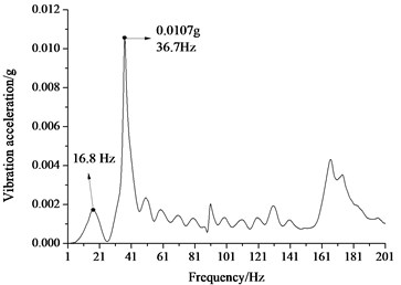
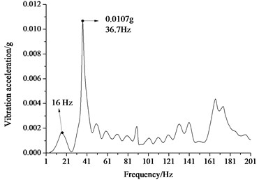
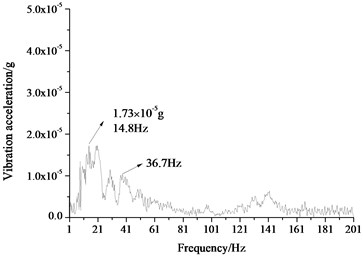
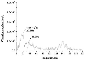
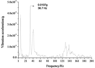
According to the time history of vertical vibration acceleration, frequency spectrum was obtained using FFT using the commercial software MATLAB. Fig. 12 shows the frequency spectrum of vertical vibration acceleration for the rubber floating-slab track with full-surface supporting. Fig. 12(a) shows the first resonant frequency of the floating slab is 16.8 Hz. The maximum vibration acceleration of the floating slab in the frequency domain is 0.0107 g at 36.7 Hz, which is the second resonant frequency. Fig. 12(b) shows the first resonant frequency of the floating slab is 16 Hz. The maximum vibration acceleration is the same as #1. From Fig. 12(c), the maximum peak value of vertical vibration acceleration of the tunnel wall is 1.73×10⁻⁵ g at 14.8 Hz. Fig. 12(d) shows the maximum peak value is 1.87×10⁻⁵ g at 20.3 Hz. Despite the frequency, where the maximum peak value is at, is different, the maximum peak values are close. The wave propagating from the floating slab to the tunnel wall was attenuated mainly at the second resonant frequency.
Fig. 12Frequency spectrum of vertical vibration acceleration of the floating-slab and the tunnel wall for the floating-slab track with full-surface supporting
a) Frequency spectrum of vertical vibration acceleration at #1
b) Frequency spectrum of vertical vibration acceleration at #2
c) Frequency spectrum of vertical vibration acceleration at #3
d) Frequency spectrum of vertical vibration acceleration at #4
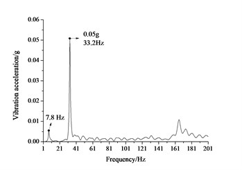
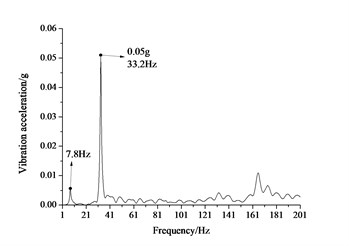
Fig. 13 shows the frequency spectrum of vertical vibration acceleration for the rubber floating-slab track with full-surface supporting. The first resonant frequency of the floating slab is 7.8 Hz. The maximum vibration acceleration of the floating slab is 0.05 g at 33.2 Hz. Compared with the full-surface supporting form, the first resonant frequency and the second resonant frequency of the linear supporting form is decreased. Fig. 13(c) shows the maximum peak value of the tunnel wall is 4.14×10⁻⁵ g at 33.2 Hz. The maximum vertical vibration acceleration of #4 also happened at 33.2 Hz, but the maximum peak value is 3.4×10⁻⁵ g.
Fig. 13Frequency spectrum of vertical vibration acceleration of the floating-slab and the tunnel wall for the floating-slab track with linear supporting
a) Frequency spectrum of vertical vibration acceleration at #1
b) Frequency spectrum of vertical vibration acceleration at #2
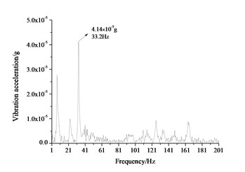
c) Frequency spectrum of vertical vibration acceleration at #3
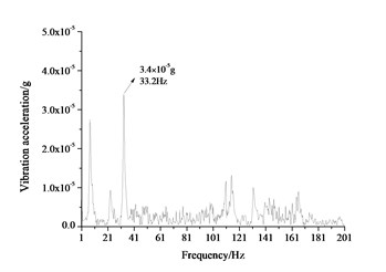
d) Frequency spectrum of vertical vibration acceleration at #4
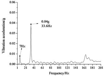
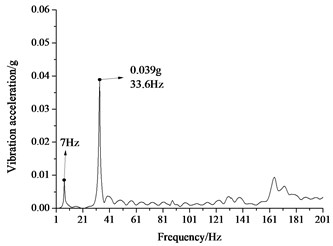
Fig. 14Frequency spectrum of vertical vibration acceleration of the floating-slab and the tunnel wall for the floating-slab track with point-like supporting
a) Frequency spectrum of vertical vibration acceleration at #1
b) Frequency spectrum of vertical vibration acceleration at #2
c) Frequency spectrum of vertical vibration acceleration at #3
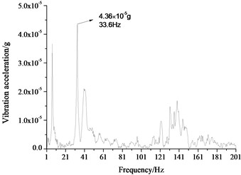
d) Frequency spectrum of vertical vibration acceleration at #4
Fig. 14 shows the frequency spectrum of vertical vibration acceleration for the rubber floating-slab track with full-surface supporting. The first resonant frequency of the floating slab is 7 Hz. The maximum vibration acceleration is 0.04 g at 33.6 Hz. The first resonant frequency is the smallest among these three kinds of the supporting forms. The maximum vibration acceleration values of #3 and #4 are 4.65×10⁻⁵ and 4.36×10⁻⁵ g separately at 33.6 Hz, which is the second resonant frequency.
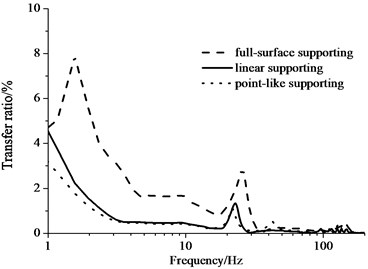
Through the frequency spectrum of the floating slab and the tunnel wall, the transfer ratio of the vibration acceleration from the floating slab to the tunnel wall can be calculated, shown in Fig. 15. As described in Fig. 15, the full-surface supporting form has the biggest transfer ratio in three kinds of supporting forms. The linear supporting form is similar as the point-like supporting form. But the point-like supporting form has the smaller transfer ratio in the low frequency domain than the linear supporting form.
Fig. 15Transfer ratio of vibration acceleration from the floating slab to the tunnel wall
6. Conclusions
In order to improve vibration reduction ability of the rubber floating-slab tracks, three kinds of supporting forms, i.e. full-surface supporting, linear supporting and point-like supporting, were discussed by the laboratory test in this paper. Through time history analysis and frequency spectrum analysis, the results show that:
1) The linear supporting form and the point-like supporting form have the smaller first resonant frequency than the full-surface supporting form, which is induced by the weakened supporting stiffness.
2) The maximum values of vibration acceleration of the floating slab for the linear supporting form and the point-like supporting form increase in the time domain and the frequency domain.
3) The point-like supporting form has the smallest transfer ratio of vibration acceleration from the floating slab to the tunnel wall compared with the linear supporting form and the full-surface supporting form.
References
-
Cox S. J., Wang A., Morison C., Carels P., Kelly R., Bewes O. G. A test rig to investigate slab track structures for controlling ground vibration. Journal of Sound and Vibration, Vol. 293, Issues 3-5, 2006, p. 901-909.
-
Zhou M., Wei K., Zhou S., Xiao J., Gong Q. Influence of different track types on the vibration response of the jointly-built structure of subway and the buildings. China Railway Science, Vol. 32, Issue 2, 2011, p. 33-40.
-
Yan Z. Q., Markine V., Gu A. J., Liang Q. H. Optimisation of the dynamic properties of ladder track to control rail vibration using the multipoint approximation method. Journal of Vibration and Control, Vol. 20, Issue 13, 2014, p. 1967-1984.
-
Lopes P., Costa P. A., Calcada R., Cardoso A. S. Mitigation of vibrations induced by railway traffic in tunnels through floating slab systems: numerical study. Eurodyn 2014: 10th International Conference on Structural Dynamics, 2014, p. 871-878.
-
Grootenhuis P. Floating track slab isolation for railways. Journal of Sound and Vibration, Vol. 51, Issue 3, 1977, p. 443-448.
-
Nelson J. T. Recent developments in ground-borne noise and vibration control. Journal of Sound and Vibration, Vol. 193, Issue 1, 1996, p. 367-376.
-
Hussein M., Hunt H. Modelling of floating-slab tracks with continuous slabs under oscillating moving loads. Journal of Sound and Vibration, Vol. 297, Issue 1, 2006, p. 37-54.
-
Geng C., Lou M. Vibration model analysis of floating slab track system. Journal of Tongji University (Natural Science), Vol. 34, Issue 9, 2006, p. 1201-1205.
-
Liu H., Zou J., Wang R. Dynamic design parameters of rubber floating slab track structure for urban mass transit. Journal of Rail Way Science and Engineering, Vol. 6, Issue 2, 2009, p. 5-11.
-
Zou J., Jiang H., Xia X. Analysis model of vertical vibration for rubber floating slab track. Journal of Traffic and Transportation Engineering, Vol. 9, Issue 4, 2009, p. 33-37.
-
Xu Q., Fan H., Meng Y., Zhou X., Shi C. Theoretical study of longitudinal connection for rubber floating slab track of subway tunnel. Journal of Traffic and Transportation Engineering, Vol. 13, Issue 4, 2013, p. 37-44.
-
Cui R., Gao L., Cai X., Zhong Y. Research on the design for the rubber vibration isolator of floating slab track. ICRE2012, China, 2012, p. 299-304.
-
Saurenman H., Phillips J. In-service tests of the effectiveness of vibration control measures on the BART rail transit system. Journal of Sound and Vibration, Vol. 293, Issues 3-5, 2006, p. 888-900.
-
Hwang S. H., Jang S. Y., Kim E., Park J. C. Static and dynamic behavior at low-frequency range of floating slab track discretely supported by rubber mounts in real-scale laboratory test. Journal of the Korean Society for Railway, Vol. 15, Issue 5, 2012, p. 485-497.
-
Montella G., Mastroianni G., Serino G. Experimental and numerical investigations on innovative floating-slab track including recycled rubber elements. Proceedings of ISMA2012-USD2012, Belgium, 2012, p. 2869-2879.
-
Wu C., Liu X., Huang X. Experimental study on aging characteristics of floating slab track rubber bearings. Noise and Vibration Control, Vol. 29, Issue 4, 2009, p. 10-13.
About this article

This project was supported by National Natural Science Foundation of China 51478353.
