Abstract
In order to investigate the effect of the guide vane outlet angle on the performance of centrifugal pumps, a centrifugal pump with guide vanes was used as the research model and its specific speed is 165. Keep all the other geometry parameters of the pump as constants, the guide vane outlet angle was designed to be 28°, 20°, 15°,10°, 5° and 3° respectively. The whole flow field in the pump under different guide vane outlet angles was simulated by commercial code CFX and the simulation was unsteady. The simulation results were validated by experiment results. According to the simulations, the hydraulic performance, internal flow and radial force of the pump under different guide vane outlet angles were compared and analyzed in detail. The research results indicate that the head and efficiency of the pump are the best when the guide vane outlet angle is 10°. With the decrease of the blade outlet angle of guide vane, the length of flow channels in the guide vane become bigger and its width gets smaller, the uniformity of inner flow in the centrifugal pump gets better, and therefore the radial force on the impeller reduces. With the decrease of the guide vane blade outlet angle, the pulsation frequency of radial force does not change, but the pulsation amplitude of the radial force reduces obviously. The vector distribution of the unsteady radial force is symmetric around the origin and mainly lies in 5 regions, which is same as the blade number of impeller.
1. Introduction
The centrifugal pump is a kind of rotating machinery and widely used in industries of chemistry, mining, petroleum and so on. There are many types of centrifugal pumps. Centrifugal pumps with guide vane are mainly used in large single pumps and multistage pumps [1]. In large single pumps, the guide vane can transfer the kinetic energy into pressure energy and reduce the radial force on an impeller. For multistage pumps, the guide vane can lead water to the next stage smoothly. So the guide vane is an extremely important component in centrifugal pumps. The effect of guide vanes on performance of the axial and mixed flow pumps has been researched carefully [2-7]. However, the guide vane in centrifugal pumps gains less attention, especially about how the guide vane can further reduce the radial force on an impeller.
Many authors contributed to the research of the radial force of centrifugal pumps. Jiang [8] compared the effect of different kinds of diffusers on the radial force of the pump. He concluded that the direction of radial force in centrifugal pumps with guide vanes does not change evidently when the flow rates rises. Okamoto [9] experimentally investigated the radial force on the impeller and found that extra frequency components may occur due to the circumferential unevenness of the pressure fluctuations on the impeller. Zhang [10] studied the effects of blade arrangements on impeller radial force and found staggered blade arrangements could significantly reduce the radial force fluctuation. Boehning [11] evaluate the radial force of blood pump with different types of volute design, the results show that single volute yields the lowest radial force. Zhao [12] compared the axial and radial forces of a centrifugal pump with three variable styles of the wear-rings and found the axial force is easier to be affected compared with the radial force. Adkins [13] theoretically predicted the radial force on the impeller and found that pressure acting on the shroud of the impeller has substantially effect on the destabilizing radial forces.
Centrifugal pump with guide vane has been studied and contributed by many authors [14-21], whose main purposes are to explore the pattern of the inner flow and to improve the hydraulic performance for the pump. However, there is no relative research about the influence of the guide vane outlet angle on the effect of the radial force and hydraulic performance of centrifugal pump.
The outlet angle is one of the most important parameters in hydraulic design of a guide vane and it has significant effect on the pump performance. In the present work, a centrifugal pump with a guide vane was used as the research model. The effects of guide vane outlet angle on the radial force and hydraulic performance of centrifugal pump were analyzed by both experimental and numerical methods. Variations for these changes have been interpreted through the changes of the inner flow distributions.
Fig. 1The sketch of test rig
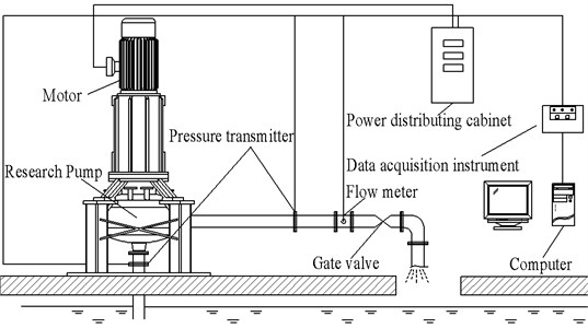
2. Model test rig
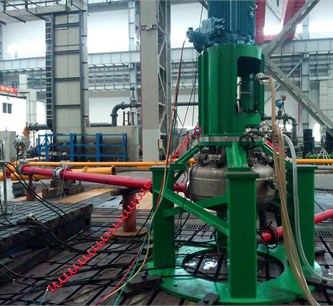
To validate the simulation results, tests of the research pump were conducted in Jiangsu University. The pump was arranged in an open test loop. The schematic arrangements of the test rig facilities are shown in Fig. 1 and photo of the pump test are shown in Fig. 2. The test-bad precedes the requirements of international grade 1 precision (ISO9906-1999) [22]. A motor that can provide a maximal power of 75 kW is used in the test loop. The motor is able to drive the pump to the designed rotation speed of 1480 r/min. The voltage and amperes of the motor were recorded during the experiment with a measurement error of 0.5 %. Two pressure transmitters are installed in the test loop to measure the inlet and outlet pressure respectively. And the measurement errors of the two pressure transmitters are both 0.1 %. A gate valve is installed near the outlet of the loop to adjust the flow rate of the pump. The turbine flow meter is mounted behind the pressure transmitter near the gate valve to measure the volumetric flow rate of the pump. And the uncertainty of the turbine flow meter is 0.1 %.
Fig. 2The test rig
3. Numerical methods
3.1. Research model
The research model is a centrifugal pump with guide vanes. Main parameters of the research model are shown in Table 1.
The guide vane in the pump is straight. Therefore, the parameters on the meridional plane of the guide vane will not be changed, when the blade outlet angle of the guide vane is redesigned. In the present research, the inlet angle of the guide vane is 8° and the outlet angle of the guide vane was designed to be 28°, 20 °, 15°, 10°, 5°and 3° respectively. All the research schemes are shown in Fig. 3.
Fig. 3Research schemes

a)3°
b)5°
c)10°
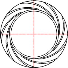
d)15°
e)20°

f)28°
Table 1Parameters of the research model
Parameter | Sign | Value |
Flow rate | (m3/h) | 300 |
Head | (m) | 20 |
Rotational speed | (r/min) | 1480 |
Specific speed | 165 | |
Impeller inlet angle | 18° | |
Impeller outlet angle | 21.2° | |
Blade number of impeller | 5 | |
Inlet angle of guide vane | 8° | |
Outlet angle of guide vane | 28, 20, 15, 10, 5, 3° | |
Blade number of guide vane | 9 |
3.2. Calculation domains
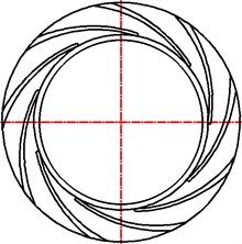
In order to improve the simulation precision, the whole flow field is considered in the calculation domains, including the leakage domain in labyrinth seal and between the impeller and the guide vane, as is shown in Fig. 4(b). The entire flow domains in the CFD model consists of annular casing, guide vane, leakage flow domain, impeller and inlet domain. The three dimensional model of calculation domains was built by Pro/E 5.0. The inlet domain and the outlet of the annular casing were properly extended to reduce the effect of boundary conditions on the inner flow. The whole calculation domains are showed in Fig. 4(a).
Fig. 4Calculation domains
a) Drawing of assembly
b) Partial enlarged view of leakage flow near the labyrinth seal
3.3. Grid generation
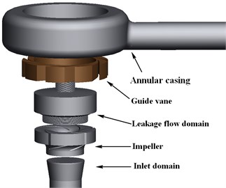
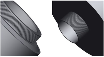
Geometrical discretization of research model is made before the numerical simulation. As the domains for calculation are quite complex, unstructured mesh of tetrahedral cells is generated by commercial code ANSYS ICEM. In addition, the flow field has already split into 5 components, whose separation enables each mesh to be generated respectively and tailored to that particular part. Due to the significant size difference between the global domain and local details, mesh for some areas was locally refined. In the leakage flow domain, the mesh near the labyrinth seal was refined to match the actual flow domain more closely. Grids for different parts are shown in Fig. 5.
3.4. Boundary conditions
Boundary conditions should be specifically chosen to give more physical meaning for pump flow simulations. At the inlet of the pump, the total pressure is used. And mass flow is used for the outlet of the annular casing. For the outlet on the leakage flow domain, the boundary condition is set as “opening”. All surfaces except the interfaces connecting different parts are imposed with a smooth nonslip boundary condition and the standard wall function is used to process the flow near the wall. Roughness of all the surfaces except interfaces is set to be 0.025 mm.
Fig. 5Grid of different parts
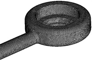
a) Annular casing
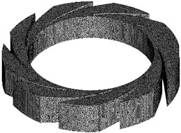
b) Guide vane (28°)
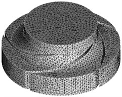
c) Impeller
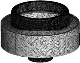
d) Leakage flow domain
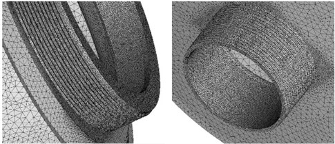
e) Refined mesh of leakage flow domain near the labyrinth seal
3.5. Numerical scheme
The fully three dimensional incompressible Navier-Stokes equations are performed using ANSYS CFX code. Discretization of the equations is carried out by using finite volume method based on finite element method. Three dimensional incompressible unsteady simulations are performed by adopting the steady simulation results as the initial conditions. As the impeller in the model keeps rotating while other parts remain stationary, multiple frames of references must be used. The impeller is set in rotary frame and the other parts are set in stationary frame. In addition, interfaces between impeller and other parts are set to be “Transient rotor-stator” while other interfaces remains to be “General connection”. Time-step for unsteady simulations is given 1.126×10⁻⁴ s, which namely means the impeller rotates for 1 degree during 1 time-step. The maximum residuals for calculations are set to be 10-5. Pressure at the inlet and outlet of the pump are monitored. Each unsteady simulation is calculated for 5 rotation cycles in order to get a stable result. This makes the total time setting for calculations to be 0.20207207 s. However, only data from the last rotation cycle is extracted for the result processing.
Table 2Grid sensitively analysis
Grid number | Head / m | |
Grid A | 2137091 | 21.31 |
Grid B | 2628395 | 21.27 |
Grid C | 2934519 | 21.46 |
Grid D | 3712175 | 21.60 |
Grid E | 4050570 | 21.53 |
Table 3Grid number of flow components
Flow components | Grid number |
All | 2934519 |
Inlet domain | 81723 |
Impeller | 364066 |
Gap cavity | 912182 |
Guide vane | 474952 |
Volute | 304168 |
3.6. Validation of grid independence
Grid independence is necessary before simulations as grid number may exert an effect on the calculation precision. So guide vane with 28°is selected to validate the grid independence. 5 sets of grids are generated and the results are shown in Table 2. As it can be seen from the table, with the grid number increasing, the head difference is less than 0.7 %. So the possibility of grid dependence can be excluded. Given the time cost for calculation considered, Grid C is selected for calculation in the end. The grid numbers for different flow domains are given in Table 3.
3.7. Selection of turbulence model
Turbulence model selection is a crucial part for numerical simulation as inappropriate turbulence model may lead to high calculation error. Therefore, the SST -, Standard -, --, -, RNG - turbulence models have been used to simulate the inner flow of the pump (28°). Compared with the data obtained from the experiment, the final calculation results of different turbulence models are listed in Table 4. It is found results calculated by Standard - are closest to the experiment data. So the Standard - turbulence model is adopted to perform the simulations in this paper.
Table 4The comparison of different models
Head / m | Head error / % | Efficiency / % | Efficiency error / % | |
SST - | 22.41 | 9.26 | 58.18 | 0.89 |
Standard - | 21.42 | 4.44 | 58.23 | 0.94 |
-- | 22.93 | 11.8 | 59.51 | 2.22 |
- | 23.21 | 13.16 | 60.21 | 2.92 |
RNG - | 21.94 | 6.97 | 58.35 | 1.21 |
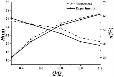
Fig. 6Comparison of numerical and experimental results (β4= 28°)
4. Validation of CFD results
Fig. 6 gives the performance curves of numerical and experimental results (28°). As illustrated in the graph, numerical performance curves are in good agreement with experimental results. For the range of 0.3-1.2, the relative errors of head and efficiency are less than 5 % and 3 % respectively. The head error is 4.53 % at the design conditions while the efficiency error is 1.51 %. This comparison between numerical and experimental results demonstrates the CFD method could predict the pump performance with acceptable accuracy.
5. Results and discussions
5.1. Influence of guide vane outlet angle on the pump performance
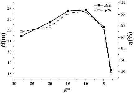
Fig. 7 shows the head and efficiency variation of the pump with the decrease of . It can be clearly seen that, with the decreasing, the head and efficiency of the pump increase at first and when 10°, the values of head and efficiency are the highest. When 10°, the head and efficiency decrease with β4 diminishing. Conclusion can be thus drawn that there is an optimal outlet angle of guide vane to achieve the highest head and efficiency. The optimal value of for this model is 10°.
Fig. 7Performance comparison
5.2. Analysis of flow field in the pump
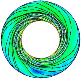
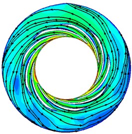
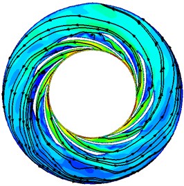
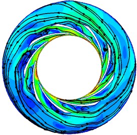
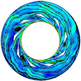
Variations of pump performance can be reflected from the changes of inner flow field. To understand the reasons for the changes of pump performances under different , the velocity contours and streamlines at the middle span of the guide vane are presented in Fig. 8. It can be seen from Fig. 8 the distributions of streamlines and velocity under different are quite similar. The velocity gradually decreases from the guide vane to the annular casing for all the cases. Streamlines in the interior of guide vanes are constrained by the edges of the guide vane. But in the annular casing, the streamlines expand in a shape of helix. Meanwhile, there is a high-speed zone near the inlet of guide vane for all the cases. This should be attributed to the dash of the flow from the impeller outlet.
The distributions of the velocity under different also show some differences. With the decreasing, the overall uniformity of the flow gradually gets better. There are many vortexes in the guide vane when 28° and 20°, but when is smaller than 15°, all vortexes disappear. This is because the length of the flow passage in the guide vane becomes bigger and its width gets smaller with the decrease of guide vane outlet angle , which can control the flow pattern in the guide vane more strictly. In this case, the flow in the annular casing also becomes smoother and the vortex disappears.
It is also can be seen from Fig. 8 that with the decreasing, the overall absolute velocity in the pump increases. For the distribution of velocity in the guide vane, the high speed zone gets bigger with decreasing. When is smaller than 10°, high speed area has basically occupied the entire flow passage. The velocity in the annular casing also changes obviously. When is 28°, the magnitude of the velocity is mainly in the range of 2-6 m/s, but when the is equal to 3°, the magnitude of the velocity rises to the range of 7-13 m/s.
Therefore, the explanation for the change of pump performance with the variation of can be given. The decrease of the guide vane outlet angle makes the internal flow in the pump more uniform, which would lead to higher head and efficiency of the pump. But if the is too small, the flow passage of the guide vane will become too narrow. In this case, the flow velocity in the guide vane is very high and the guide vane cannot covert kinetic energy into pressure energy very well, which means more hydraulic loss in the pump. The above analysis can be verified by Fig. . In Fig. 7, the head and efficiency of the pump decrease dramatically when the is smaller than 10°.
Fig. 8Velocity contours and streamlines (m/s)
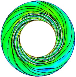
a)3°
b)5°
c)10°
d)15°
e)20°
f)28°

5.3. Analysis of radial force in the pump
5.3.1. Average value of radial force
The radial force on the impeller is a vector with magnitude and direction and it changes with the rotation of impeller. In order to compare the radial force under different , the radial force vector’s modulus at every time-step in the last calculation cycle is extracted and the average values of all the radial force modulus are calculated based on these data. The average values of the radial force under different are displayed in Fig. 9.
Fig. 9Average radial force on the impeller
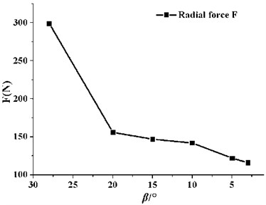
It can be seen from Fig. 9 that the radial force on the impeller reduces obviously as decreases. When the varies from 28° to 20°, the average value of the radial force on the pump impeller decreases from 299 N to 156 N, which results in a significant falling as much as 47.8 %. But when is smaller than 20°, the variation gradient is not obvious. The average value of the radial force decreases from 156 N to 116 N, only 25.6 %, when the varies from 20° to 3°.
The origin of the radial force on the impeller is from the nonuniform internal flow in the pump. So the more uniform the internal flow becomes, the smaller the radial force gets. Based on the analysis above, the decrease of the guide vane outlet angle can improve the uniformity of the internal flow. Therefore, the average value of the radial force shows a trend of dropping as the guide vane outlet angle decreases.
5.3.2. Analysis for time domain characteristics of radial force
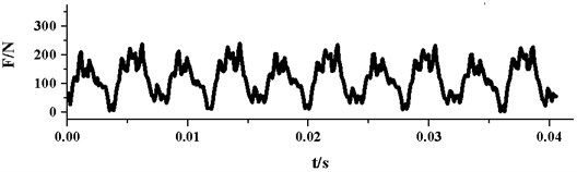
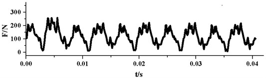
Based on the numerical simulations, the radial force vector’s modulus at every time-step in the last rotation cycle is calculated. Fig. 10 presents the time domain curves of radial force under different . As it can be seen from the graph, all the pulsations of the radial forces are periodic. In one impeller rotation cycle, the radial force pulsation generally appears periodically for 5 times. This phenomenon results from the rotor-stator interaction between the impeller and the guide vane, because the blade number of the impeller is 5. For each pulsation, there are one large peak and one small peak, which may be related to the structure of the annular casing. As the annular casing is symmetrical, which is different from traditional spiral volute, this may double the interactions between impeller and annular casing. With the decrease of , the two peaks in each pulsation get more similar, this may be due to the improvement of flow uniformity in the pump.
It can also be seen from Fig. 10, the peak values and amplitudes of the pulsations reduce with the decreasing. Table 5 displays specific data for maximum, minimum and peak-to-peak amplitude of radial force pulsation under different . When falls from 28° to 3°, the maximum of radial force reduces from 526 N to 240 N, meanwhile the minimum value decreases from 18 N to 3 N. The maximum of radial force drops more sharply than the minimum. Therefore, the peak-to-peak amplitude of radial force shows a trend of falling. Correspondingly, the pulsation amplitude of radial force decreases from 508 N to 237 N and the decline reaches as much as 53 %.
Table 5Amplitude of radial force (N)
Maximum /N | Minimum /N | Peak-to-peak amplitude / N | |
28° | 526 | 18 | 508 |
20° | 396 | 15 | 381 |
15° | 330 | 15 | 315 |
10° | 266 | 14 | 252 |
5° | 258 | 8 | 251 |
3° | 240 | 3 | 237 |
5.3.3. Analysis for frequency domain characteristics of radial force
Radial force pulsations result from the rotor-stator interaction, but only through the time domain analysis, it could not be fully understood. In order to determine the main source motivating the radial force pulsations and determine the frequency components of radial force, frequency analysis should be conducted. Fig. 11 shows the frequency spectra of radial force pulsation with different . As it can be seen from the graph, the pulsation of radial force mainly appears at low frequencies. The pulsation amplitude at the blade passing frequency and its harmonic frequencies usually are very big. The largest pulsation amplitude of radial force under different is at the same frequency and the frequency is 247 Hz, which is 10 times of the rotational frequency and 2 times of the blade passing frequency. This illustrates that the change of does not alter the frequency of the largest amplitude.
Fig. 10Time domain curves of radial force pulsation
a)3°
b)5°
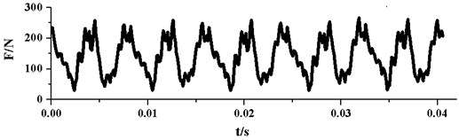
c)10°
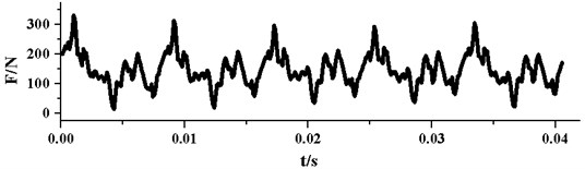
d)15°
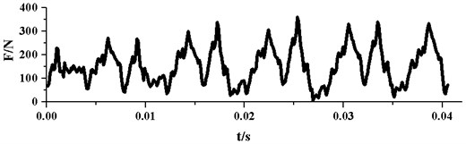
e)20°
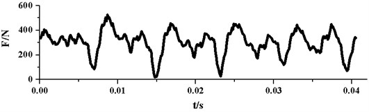
f)28°
According to Eisenmann [23], for centrifugal pumps with guide vanes, the pulsation frequency for the largest amplitude in the pump may be × impeller blade passing frequency, × guide vane passing frequency or an interference frequency (× rotation frequency) determined by interaction between impeller and guide vane ( is a positive integer). In reference [22], he pointed out when the blade number of the impeller and guide vane are 5 and 9 respectively, the frequency for the largest amplitude is more likely to be 2× impeller blade passing frequency. For the research model in this paper, the pulsation frequency for the highest amplitude is just 2× impeller blade passing frequency, which indicates the main factor of the radial force fluctuations is the interaction between impeller and guide vane. This is mainly due to the small gap between rotary impeller and stationary guide vane, the gap is just 3 mm. Therefore, the interference frequency is the main pulsation frequency in the pump. Also, this result can validate the CFD method in this paper.
Fig. 11Frequency spectra of radial force pulsation
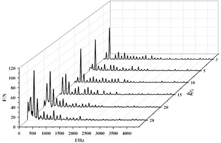
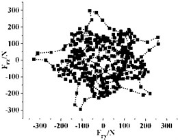
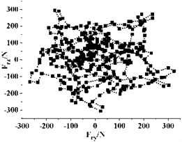
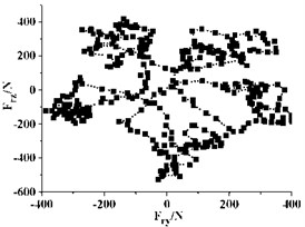
Fig. 12Distribution of radial force vectors
a)3°
b)5°
c)10°
d)15°
e)20°
f)28°
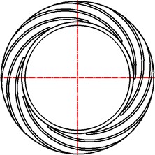
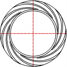
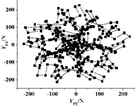
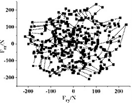
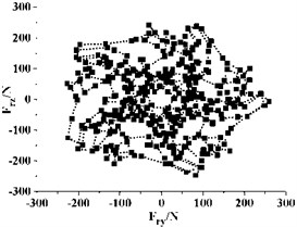
5.3.4. Analysis for the vector distribution of radial force
Fig. 12 gives the distribution of radial force vectors in the last rotation cycle. Every point in the graph represent the radial force of the impeller at one instant. It can be seen that the direction and magnitude of the radial force vector change dramatically with time. The vector distribution of radial force under different in a cycle is regular and (0, 0) is the symmetric center of the vector distribution for all the cases. The radial force vectors are mainly in 5 regions, and the number is same as the blade number of the impeller. For all the cases, the vector distribution of radial force is almost at every direction in the graph, which means that the radial force changes drastically with the rotation of impeller.
For different , there is also something different in each distribution, especially the concentration of radial forces vector. When 28°, the radial force vectors are mainly far away from the center. This indicates that most radial forces are very big under this . Also, it can be seen from Fig. 12(f) that very few radial forces vectors lie in the second and third quadrants. Most of the vectors lie in areas that are parallel to the axes and the distribution presents obvious inhomogeneity. This inhomogeneity is detrimental to the running of the pump, as large alternating load will shorten the fatigue life of pump and bring potential risk for the long time running. With the decreasing, the uniformity of vector distribution improves, especially when drops from 15° to 10°, and most of the vectors get closer to the center. This indicates that a small can reduce the occurrence frequency of big radial force vector.
6. Conclusions
In this paper, a centrifugal pump with guide vane is used as the research model and the effect of outlet angle of guide vane is investigated in detail. The analysis of the results enables the following conclusions to be drawn.
1) With the decrease of the outlet angle of the guide vane, the flow uniformity inside the pump becomes better, which can improve the pump head and efficiency. But when the outlet angle of the guide vane is too small, the guide vane cannot convert the kinetic energy into pressure energy efficiently and the loss in the pump increases rapidly at the same time. When the outlet angle of the pump is 10°, the head and efficiency of the pump are the best.
2) When the outlet angle of guide vane decreases, the length of the flow passage in the guide vane increases, which can improve the control ability of the guide vane, and make internal flow in the pump more uniform, and finally reduce the radial force of the pump.
3) With the decrease of the guide vane outlet angle, the pulsation amplitude of radial force also becomes smaller. But the frequency for the largest amplitude keeps constant when the outlet angle of guide vane changes. The frequency for the largest amplitude under different outlet angle is always 247 Hz, which is 2 times of the blade passing frequency. This is determined by the impeller-guide vane interaction in the pump.
4) A small outlet angle of the guide vane can enhance the uniformity of radial force vector distribution. The radial force vectors are in a center symmetric distribution, which mainly lie in 5 regions, corresponding to the blade’s number of the impeller.
References
-
Yuan S. Q., Shi W. D., Liu H. L., et al. Theory and Technology of Pump. China Machine Press, Beijing, 2014.
-
Qian Z. D., Wang F., Wang Z. Y, et al. Experimental study on hydraulic performance of saddle zone in axial flow pump with adjustable guide vane. Journal of Drainage and Irrigation Machinery Engineering, Vol. 31, Issue 6, 2013, p. 461-465.
-
Kim S., Choi Y. S., Lee K. Y., et al. Interaction of impeller and guide vane in a series-designed axial-flow pump. IOP Conference Series: Earth and Environmental Science, Vol. 15, Issue 3, 2012, p. 032027.
-
Hu F. F., Chen T., Wu D. Z., et al. Experimental study of cavitation vibration and noise of guide vane mixed flow pump. Journal of Drainage and Irrigation Machinery Engineering, Vol. 31, Issue 12, 2013, p. 1021-1024.
-
Yang F., Liu C., Tang F. P., et al. Numerical simulation on hydraulic performance of axial-flow pumping system with adjustable inlet guide vanes. Transactions of the Chinese Society for Agricultural Machinery, Vol. 45, Issue 5, 2014, p. 51-58.
-
Liang J. D., Lu L. G., Xu L., et al. Influence of flow velocity circulation at guide vane outlet of axial-flow pump on hydraulic loss in outlet conduit. Chinese Society of Agricultural Engineering, Vol. 28, Issue 1, 2012, p. 55-60.
-
Bing H., Cao S. L., Tan L., et al. Effects of diffuser vane on mixed-flow pumps performance. Journal of Drainage and Irrigation Machinery Engineering, Vol. 30, Issue 2, 2012, p. 125-130.
-
Jiang W., Li G. J., Zhang X. S. Numerical analysis the influence of collector configuration on radial force for centrifugal pump. Journal of Drainage and Irrigation Machinery Engineering, Vol. 31, Issue 2, 2013, p. 93-97.
-
Okamoto H. An experimental study on the fluid forces induced by rotor-stator interaction in a centrifugal pump. International Journal of Rotating Machinery, Vol. 9, Issue 2, 2003, p. 135-144.
-
Zhang Z. C., Wang F. J., Yao Z. F. Investigation on impeller radial force for double-suction centrifugal pump with staggered blade arrangement. Iop Conference, Vol. 52, Issue 4, 2013, p. 668-672.
-
Boehning F., Timms D. L., Amaral F., et al. Evaluation of hydraulic radial forces on the impeller by the volute in a centrifugal rotary blood pump. Artificial Organs, Vol. 35, Issue 8, 2011, p. 818-825.
-
Zhao W. G., He M. Y., Qi C. X., et al. Research on the effect of wear-ring clearances to the axial and radial force of a centrifugal pump. Iop Conference, Vol. 52, Issue 4, 2013, p. 668-672.
-
Adkins D. R., Brennen C. E. Analyses of hydrodynamic radial forces on centrifugal pump impellers. Journal of Fluids Engineering, Vol. 110, Issue 1, 1988, p. 20-28.
-
Zhou L., Shi W. D., Lu W. G. Performance analysis on deep-well centrifugal pump guide vanes based on numerical simulation. Chinese Society of Agricultural Engineering, Vol. 27, 2011, p. 38-42.
-
Cao S. L., Tan L., Gui S. B., et al. Design and experiment of inlet guide vane for centrifugal pump. Chinese Society of Agricultural Engineering, Vol. 41, Issue 1, 2010, p. 1-5.
-
Tan L., Cao S. L., Gui S. B. Experiment and numerical simulation of cavitation performance for centrifugal pump with inlet guide vane. Journal of Mechanical Engineering, Vol. 46, Issue 18, 2010, p. 177-182.
-
Wang W. J., Yuan S. Q., Pei J. Effects of relative setting position between diffuser and volute on flow characteristics of residual heat removal pump. Journal of Drainage and Irrigation Machinery Engineering, Vol. 32, Issue 9, 2014, p. 759-764.
-
Wuibaut G., Bois G., Dupont P., et al. PIV measurements in the impeller and the vaneless diffuser of a radial flow pump in design and off-design operating conditions. Journal of Fluids Engineering, Vol. 124, Issue 3, 2002, p. 791-797.
-
Shi F., Tsukamoto H. Numerical study of pressure fluctuations caused by impeller-diffuser interaction in a diffuser pump stage. Journal of Fluids Engineering, Vol. 123, Issue 3, 2001, p. 466-474.
-
Sinha M., Pinarbasi A., Katz J. The flow structure during onset and developed states of rotating stall within a vaned diffuser of a centrifugal pump. Journal of Fluids Engineering, Vol. 123, Issue 3, 2001, p. 490-499.
-
Segala W., Stel H., Hungria V., et al. Numerical simulation of the flow in a centrifugal pump with a vaned diffuser. Joint Fluids Engineering Conference, American Society of Mechanical Engineers, 2011, p. 1791-1800.
-
International Organization for Standardization. ISO 9906 Rotodynamic Pumps-Hydraulic Performance Acceptance Testsgrades 1 and 2. British Standards Institution, Geneva, 1999.
-
Eisenmann R. C. Machinery Malfunction Diagnosis and Correction: vibration analysis and troubleshooting for the process industries. Prentice Hall, Upper Saddle River, 1998.
About this article

The authors gratefully acknowledge the support from the Key Projects in the National Science and Technology Pillar Program of China (2013BAK06B02), the Foundation of Jiangsu Province (Grant Nos. BE2014116, BY2014123-07, ZBZZ-040), National Natural Science Foundation of China (Grant No. 51309119), and Priority Academic Program Development of Jiangsu Higher Education Institutions (PAPD).
