Abstract
The floating-slab track is one of the best methods to reduce the vibration from the underground railway. In this paper, the rubber floating-slab track was studied. The train-track model coupled with the track-tunnel-surrounding soil model was built, which was verified by the results of the in-site test. Through this model, the quality of the rubber floating-slab track was optimized by the multi-island genetic algorithm. The optimized Z vibration level was reduced by 4.92 dB with the density of the floating slab 2306 kg/m3, the Young’s modulus of the floating slab 3.21×10¹⁰ N/m2, the density of the rubber bearing 730 kg/m3 and the Young’s modulus of the rubber bearing 9.55×10⁸ N/m2.
1. Introduction
Vibration generated by underground railways is one of the most serious engineering problems. The vibration of the subway railway will result in structural vibrations and re-radiated noise [1, 2]. There are many measures to control this vibration. The floating-slab track is one of them.
The floating slab can be continuous or discontinuous [3], which mainly can be supported by rubber bearings or steel-springs. In the Singapore Mass Rapid Transit (SMRT) system, the discontinuous floating-slab track supported by the resilient pads was used [4]. In the San Francisco Bay Area Rapid Transit (BART) system, the discontinuous floating-slab track also was used, which was supported by rubber pads [5]. In Xi’an subway line 2, China, the continuous rubber floating-slab track was used. Furthermore, the steel-spring floating-slab track was used in Bejing subway line 5, China [6].
Generally, the methods studying the floating-slab track are to build the two-dimensional model or the three-dimensional model. Using the two-dimensional model, both the discontinuous floating slab and the continuous floating slab can be analyzed. Cui and Chew [4] analyzed the effectiveness of the discontinuous floating-slab track to stationary/moving harmonic loads by the receptance method. Hussein and Hunt [7-9] studied the discontinuous/continuous floating-slab track by the Fourier-Repeating-unit method, the Periodic-Fourier method and the Modified-phase method. Similarly, Gupta and Degrande [10] build the model of the discontinuous/continuous floating-slab track, which was coupled with the tunnel soil system by a periodic approach. Furthermore, some others did this job as well [11-14].
However, the two-dimensional model only can analyze the full supporting accurately. If the floating slab rests on the steel-springs, i.e. the point supporting, the two-dimensional model cannot be employed to analyze the characteristic of the floating-slab track. The results will not be reasonable. At this time, the three-dimensional model must be built. Usually, it is accomplished by the numerical model, e.g. the finite element method. Lei and Jiang [15] build the finite element model of the steel-spring floating-slab track to analyze the effectiveness of vibration reduction. Geng et al. [16] constructed a 3D finite element model to analyze the normal models of the rubber floating-slab track. Eigenfrequencies of the floating slab with two densities were analyzed under different stiffness of the rubber bearing and the fastener.
Besides the theoretical analysis, some researchers performed the in-site test or the laboratory tests. Saurenman and Phillips [5] tested the rubber floating-slab track used on the current San Francisco Bay Area Rapid Transit (BART) system. Hwang et al. [17] performed the laboratory mock-up test to understand the dynamical behaviors of the rubber floating-slab track more accurately. Furthermore, some ones studied the material of the rubber bearings. Wu et al. [18] researched the physical deterioration of the rubber bearings affected by air oxidation, ozone ageing and the random fatigue loads. Montella et al. [19] introduced an innovative floating-slab track supported by the recycled rubber bearings.
In this paper, our focus is the rubber floating-slab track. The present contribution aims to improve the ability of vibration reduction of the rubber floating-slab track through optimizing the properties of the floating slab and the rubber bearings. This paper is organized as follows. Section 2 introduces the mathematical models including the train-track sub-model and the track-tunnel-surrounding soil sub-model. To verify the model, the in-site test is performed in Section 3. Section 4 gives the optimization objective and parameters of the rubber floating-slab track. Then, the numerical model coupled with the multi-island genetic method is employed to optimize the ability of vibration reduction of the rubber floating-slab track in Section 5. Conclusions are in Section 6.
2. Numerical models
2.1. Train-track sub-model
The numerical model was divided into two sub-models. The first sub-model was the train-track sub-model, from which the contact force between the train wheels and the rail was obtained. The second sub-model was the track-tunnel-surrounding soil sub-model, which was a finite element model, built in the software Abaqus.
Fig. 1Projection of the real train in the 2D train-track sub-model
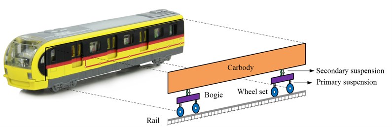
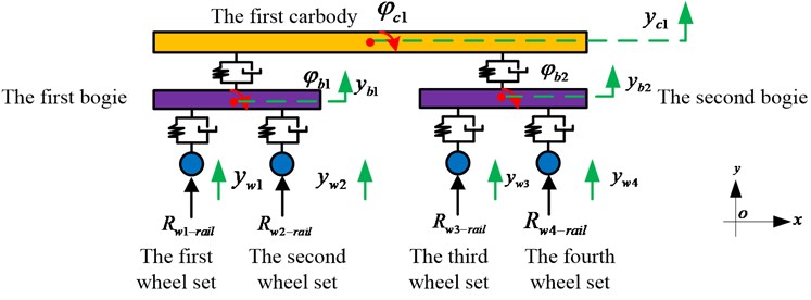
Fig.1 illustrated the relationship between the real train and the mathematical model of the train in the 2D train-track sub-model. The main components of the train are the car body, the bogie and the wheel set. The primary suspension is used to connect the bogie and the wheel set. Similarly, the secondary suspension is employed to connect the car body and the bogie. In this paper, the train-track sub-model is a 2D model. Thus, one car body has two freedom degrees. One bogie has two freedom degrees. One-wheel set has only one freedom degree. Fig. 2 shows the details of the freedom degrees for different components. is the vertical displacement of the first car body, is the rotation of the first car body, is the vertical displacement of the th bogie, is the rotation of the th bogie, is the vertical displacement of the th wheel set.
Then, we can build the dynamic equations of the train model in matrix as follows:
where is the vertical displacement of the train in the direction as shown in Fig. 2:
is the vertical velocity of the train:
is the vertical acceleration of the train:
is the force loading on the train:
is the mass matrix of the train:
is the damping matrix of the train:
is the stiffness matrix of the train:
is the mass of the first car body, is the mass of the th bogie, is the mass of the th wheel set, is the interaction force between the th wheel set and the rail, is the vertical stiffness of the primary suspension, is the vertical damping of the primary suspension, is the vertical stiffness of the secondary suspension, is the vertical damping of the secondary suspension, is the distance between two wheel sets, is the distance between two bogies, is the moment of inertia of the th bogie, is the moment of inertia of the first car body.
In this paper, the rail was simplified to be a simply supported beam [20]. The governing equation of the rail is
where, is the vertical displacement of the rail at the position when the time is , is the Young’s modulus of the rail, is the area moment of inertia of the rail, is the density of the rail per meter, is the force on the rail, i.e. the interaction force between the wheel sets and the rail in this case , is the number of the wheel sets, is the vertical stiffness of the fastener, is the vertical damping of the fastener.
Fig. 2Freedom degrees of the train in 2D train-track sub-model
The force of Hertz contact, which connects the train model and the rail model, is:
where, is the th wheel set, is the interaction constant, is the vertical displacement of the th wheel set at the position , is the vertical displacement of the rail at the position , is the irregularity of the rail at the position .
2.2. Track-tunnel-surrounding soil sub-model
The finite element model for the track-tunnel-surround soil sub-model was built in the finite element software Abaqus to analyze and optimize the ability of vibration reduction of the rubber floating-slab track loaded by the wheel-rail force from the train-track sub-model.
In order to save the calculation time in the optimization process, only the track, the rubber bearing, the tunnel and the surrounding soil were built in Abaqus. Furthermore, the infinite elements were adopted to avoid the wave reflection at the boundaries. The longitudinal size of the model is 100 m. The wheel-rail force was loaded at the rail position in the track-tunnel-surrounding soil sub-model as shown in Fig. 3.
3. Verification of the calculation results
3.1. In-site test
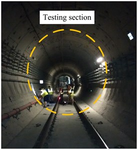
In order to verify that the results calculated by the above numerical model are reasonable, Xi’an subway line 2, in Shanxi province, China, was tested where the rubber floating-slab track was used. The rubber floating-slab track was constructed in the shielded tunnel. The train was B-type train according to the category of Chinese subway train. The speed of the train was about 40 km/h when it passed through the testing section.
Fig. 3Track-tunnel-surrounding soil sub-model built in Abaqus
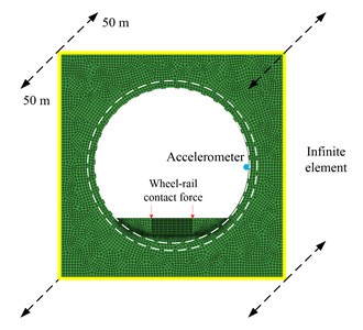
Fig. 4The in-site test in Xi’an subway line 2
The vertical acceleration of the tunnel wall, shown in Fig. 5, needs to be measured according to the Chinese code, Technical code for floating slab track [21]. As the requirement of the code, the distance between the rail top and the accelerometer is about 1.25 m. In this case, a 5 g accelerometer was used. The frequency range of the accelerometer is from 0.1 Hz to 2000 Hz.
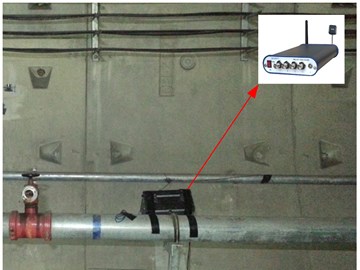
The data acquisition was fixed firmly to the pipe on the tunnel wall in order not to affect the operation safety, shown in Fig. 6.
Fig. 5Accelerometer’s position
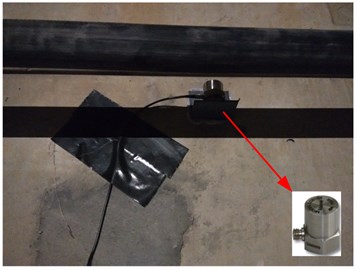
Fig. 6The data acquisition system was fixed firmly
3.2. Result comparison between the numerical model and the in-site test
The main parameters of the B-type train are in Table 1. The density of the rail is 60 kg/m, the Young’s modulus 2.1×10¹¹ Pa, the section area 7.6×10⁻³ m2, the area moment of inertia 3.04×10⁻⁵ m4. The stiffness of the fastener is 7.8×10⁷ N/m, the damping of the fastener is 5×10⁴ N∙s/m. The spacing distance between the fasteners is 0.6 m.
The Table 2 shows the density, the Young’s modulus and the Possion’s ratio of the track, the tunnel and the surrounding soil.
Table 1Parameters of the B-type train
Components | Parameters |
Mass of the car body | 35000 (kg) |
Mass of the bogie | 4600 (kg) |
Mass of the wheel set | 1420 (kg) |
Moment of inertia of the car body | 1700000 (kg∙m2) |
Moment of inertia of the bogie | 9620 (kg∙m2) |
Vertical stiffness of the primary suspension | 2.45 (MN/m) |
Vertical damping of the primary suspension | 0.24 (MN∙s/m) |
Vertical stiffness of the secondary suspension | 2.08 (MN/m) |
Vertical damping of the secondary suspension | 0.24 (MN∙s/m) |
Distance between two bogies | 12.6 (m) |
Distance between two Wheel sets | 2.2 (m) |
Table 2Properties of the track, the tunnel and the surrounding soil
Components | Density (kg/m3) | Young’s modulus (N/m2) | Possion’s ratio |
Floating slab | 2500 | 3.1×10¹⁰ | 0.167 |
Rubber bearing | 1000 | 8×10⁸ | 0.47 |
Invert | 2200 | 3×10¹⁰ | 0.2 |
Shielded tunnel | 2350 | 3.6×10¹⁰ | 0.2 |
Surrounding soil | 1990 | 3.1×10⁸ | 0.33 |
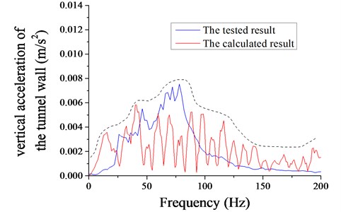
The vertical acceleration of the tunnel wall in the frequency domain, ranging from 1 Hz to 200 Hz, was calculated by the numerical model, which was compared with the tested result as shown in Fig. 7. Obviously, the tested result was more complicated than the calculated result. Because of the simplification of the train, the track, the tunnel and the surrounding soil, the numerical model lost some components. Thus, the values at some frequencies were very small. Although the numerical model was not accurate, the tendency of the values calculated by the numerical model was close to the in-site test. Therefore, the numerical model was adopted to analyze the following contents.
Fig. 7Frequency spectrum of the vertical acceleration of the tunnel wall from the numerical model and the in-site test
4. Optimization objective and parameters
According to the code, Technical code for floating slab track, the vibration level of the tunnel wall was adopted to assess the ability of vibration reduction of the floating-slab track [21]. The definition of the vibration level as follow:
where, is the vibration level at the 1/3 octave frequency for the number , is the weighted factor for the number . Table 3 shows the details for the different numbers [22].
Table 3Weighted factor in 1/3 octave frequency
Number | Frequency (Hz) | Weighted factor (dB) | Number | Frequency (Hz) | Weighted factor (dB) |
1 | 1 | –6.33 | 13 | 16 | –2.28 |
2 | 1.25 | –6.29 | 14 | 20 | –3.93 |
3 | 1.6 | –6.12 | 15 | 25 | –5.8 |
4 | 2 | –5.49 | 16 | 31.5 | –7.86 |
5 | 2.5 | –4.01 | 17 | 40 | –10.05 |
6 | 3.15 | –1.9 | 18 | 50 | –12.19 |
7 | 4 | –0.29 | 19 | 63 | –14.61 |
8 | 5 | 0.33 | 20 | 80 | –17.56 |
9 | 6.3 | 0.46 | 21 | 100 | –21.04 |
10 | 8 | 0.31 | 22 | 125 | –25.35 |
11 | 10 | –0.1 | 23 | 160 | –30.91 |
12 | 12.5 | –0.89 | 24 | 200 | –36.38 |
In order to improve the ability of vibration reduction of the rubber floating-slab track, four parameters, i.e. the density of the floating slab , the Young’s modulus of the floating slab , the density of the rubber bearing and the Young’s modulus of the rubber bearing , were analyzed. According to the engineering suggestions, the ranges of these four parameters were 2200 kg/m3 2400 kg/m3, 2.2×10¹⁰·N/m2 3.8×10¹⁰ N/m2, 500 kg/m3 1500 kg/m3, 5×10⁸ N/m2 10×108 N/m2.
5. Optimization by the numerical model coupled with the multi-island genetic algorithm
5.1. Optimization procedure
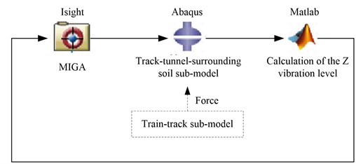
Three softwares were employed to accomplish this procedure. Firstly, the multi-island genetic algorithm was used in the software Isight. Through Isight, the software Abaqus was activated. The vertical vibration acceleration of the tunnel wall in the time domain was calculated in the Abaqus. Then, the software Matlab was employed to analyze the data from the Abaqus, i.e. the vibration level of the tunnel wall, i.e. the optimization objective, was calculated. According to the calculated vibration level, Isight adjusted the values of four parameters, the density of the floating slab, the Young’s modulus of the floating slab, the density of the rubber bearing and the Young’s modulus of the rubber bearing in the inp document, which was the input document of the Abaqus. Fig. 8 shows the workflow of the optimization procedure.
Fig. 8Workflow of the program
The parameters of the multi-island genetic algorithm were sub-population size 10, number of island 3, number of generation 10, rate of crossover 0.8, rate of mutation 0.03, rate of migration 0.25, interval of migration 5.
5.2. Optimization results
The program described above was operated for the minimum vibration level. Fig. 9 shows the value of the density of the floating slab in the optimization process. The value of the density of the floating slab is 2306 kg/m3for the minimum vibration level.
Fig. 10 shows the value of the Young’s modulus of the floating slab in the optimization process. The value of the Young’s modulus of the floating slab is 3.21×10¹⁰ N/m2 for the minimum Z vibration level finally.
Fig. 9Density of the floating slab with calculation numbers
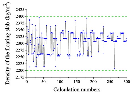
Fig. 10Young’s modulus of the floating slab with calculation numbers
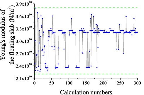
Fig. 11 shows the value of the density of the rubber bearing with the calculation numbers. The value of the density of the rubber bearing is 730 kg/m3 for the minimum vibration level.
Fig. 12 shows the value of the Young’s modulus of the rubber bearing with the calculation numbers. The value of the Young’s modulus of the rubber bearing is 9.55×10⁸ N/m2 for the minimum vibration level.
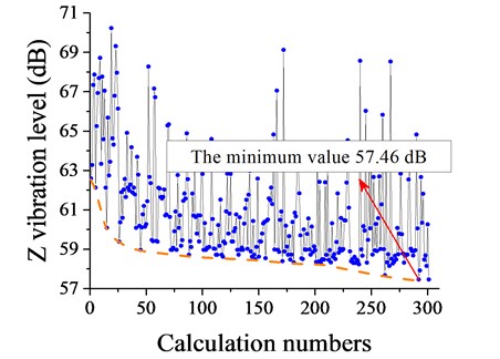
Fig. 13 shows the optimization process of the vibration level. Obviously, the vibration level decreases with the optimization numbers, especially at the start of the optimization. Eventually, the vibration level stops at 57.46 dB, which is the minimum value in the total optimization process.
Fig. 11Density of the rubber bearing with calculation numbers
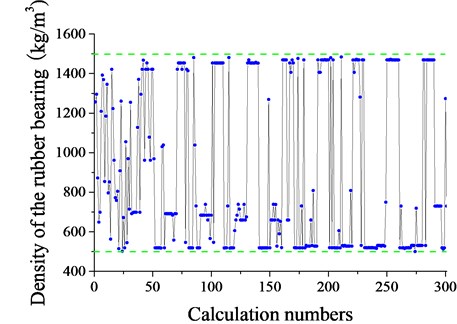
Fig. 12Young’s modulus of the rubber bearing with calculation numbers
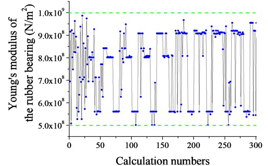
Fig. 13Z vibration level of the tunnel wall with calculation numbers
The Z vibration levels were compared between the present rubber floating-slab track and the optimized rubber floating-slab track. The parameters of the present rubber floating slab track were the density of the floating slab 2500 kg/m3, the Young’s modulus of the floating slab 3.1×10¹⁰ N/m2, the density of the rubber bearing 1000 kg/m3 and the Young’s modulus of the rubber bearing 8×10⁸ N/m2. The vibration of the present rubber floating-slab track is 62.38 dB. Therefore, the vibration level was improved by 4.92 dB.
6. Conclusions
In order to improve the ability of vibration reduction of the rubber floating-slab track, the numerical model coupled with the multi-island genetic algorithm was built. The numerical model consists of the train-track sub-model and the track-tunnel-surrounding soil sub-model, which was verified by the result of the in-site test in Xi’an subway line 2, Shanxi province, China. Through the numerical model coupled with the multi-island genetic algorithm, the vibration level was improved by 4.92 dB with the density of the floating slab 2306 kg/m3, the Young’s modulus of the floating slab 3.21×10¹⁰ N/m2, the density of the rubber bearing 730 kg/m3 and the Young’s modulus of the rubber bearing 9.55×10⁸ N/m2 compared with the present rubber floating-slab track.
References
-
Grootenhuis P. Floating track slab isolation for railways. Journal of Sound and Vibration, Vol. 51, Issue 3, 1977, p. 443-448.
-
Nelson J. T. Recent developments in ground-borne noise and vibration control. Journal of Sound and Vibration, Vol. 193, Issue 1, 1996, p. 367-376.
-
Wilson G. P. Use of floating-slab track bed for noise and vibration abatement. Transportation Research Record, Vol. 653, 1977, p. 45-58.
-
Cui F., Chew C. H. The effectiveness of floating slab track system. Part 1: Receptance methods. Applied Acoustics, Vol. 61, Issue 4, 2000, p. 441-453.
-
Saurenman H., Phillips J. In-service tests of the effectiveness of vibration control measures on the BART rail transit system. Journal of Sound and Vibration, Vol. 293, Issues 3-5, 2006, p. 888-900.
-
Li K., Liu W., Sun X., Ding D., Yuan Y. In-situ test of vibration attenuation of underground line of Beijing metro line 5. Journal of the China Railway Society, Vol. 33, 2011, p. 112-118.
-
Hussein M., Hunt H. Modelling of floating-slab track with discontinuous slab. Part 2: Response to moving trains. Low Frequency Noise, Vibration and Active Control, Vol. 25, Issue 2, 2006, p. 111-118.
-
Hussein M., Hunt H. Modelling of floating-slab track with discontinuous slab. Part 1: response to oscillating moving loads. Low Frequency Noise, Vibration and Active Control, Vol. 25, Issue 1, 2006, p. 23-39.
-
Hussein M. F. M., Hunt H. E. M. Modelling of floating-slab tracks with continuous slabs under oscillating moving loads. Journal of Sound and Vibration, Vol. 297, Issue 1, 2006, p. 37-54.
-
Gupta S., Degrande G. Modelling of continuous and discontinuous floating slab tracks in a tunnel using a periodic approach. Journal of Sound and Vibration, Vol. 329, Issue 8, 2010, p. 1101-1125.
-
Yuan J., Zhu Y., Wu M. Vibration characteristics and effectiveness of floating slab track system. Journal of Computers, Vol. 4, Issue 12, 2009, p. 1249-1254.
-
Zou J., Jiang H., Xia X. Analysis model of vertical vibration for rubber floating slab track. Journal of Traffic and Transportation Engineering, Vol. 9, Issue 4, 2009, p. 33-37.
-
Xu Q., Fan H., Meng Y., Zhou X., Shi C. Theoretical study of longitudinal connection for rubber floating slab track of subway tunnel. Journal of Traffic and Transportation Engineering, Vol. 13, Issue 4, 2013, p. 37-44.
-
Kuo C., Huang C., Chen Y. Vibration characteristics of floating slab track. Journal of Sound and Vibration, Vol. 317, Issues 3-5, 2008, p. 1017-1034.
-
Lei X., Jiang C. Analysis of vibration reduction effect of steel spring floating slab track with finite elements. Journal of Vibration and Control, Vol. 2014, 2014, p. 1-10.
-
Geng C., Lou M. Vibration model analysis of floating slab track system. Journal of Tongji University (Natural Science), Vol. 34, Issue 9, 2006, p. 1201-1205.
-
Hwang S. H., Jang S. Y., Kim E., Park J. C. Static and dynamic behavior at low-frequency range of floating slab track discretely supported by rubber mounts in real-scale laboratory test. Journal of the Korean society for railway, Vol. 15, Issue 5, 2012, p. 485-497.
-
Wu C., Liu X., Huang X. Experimental study on aging characteristics of floating slab track rubber bearings. Noise and Vibration Control, Vol. 29, Issue 4, 2009, p. 10-13.
-
Montella G., Mastroianni G., Serino G. Experimental and numerical investigations on innovative floating-slab track including recycled rubber elements. Proceedings of ISMA2012-USD2012, Belgium, 2012, p. 2869-2879.
-
Zhai W. Vehicle-Track Coupled Dynamics. 2014.
-
Technical Code for Floating Slab Track. MOHURD, 2012.
-
Mechanical Vibration and Shock-Evaluation of Human Exposure to Whole-Body Vibration-Part 1: General Requirements. ISO, 1997.
Cited by
About this article

This project was supported by National Natural Science Foundation of China 51478353.
The authors declare that there is no conflict of interests regarding the publication of this article.
